These Komatsu PC300-8, PC300LC-8, PC350-8 Crawler Excavators are mid-size machines used for bulk earthmoving, trenching, loading trucks, and quarry work. The Shop Manual (SEN01983-24) is what shop mechanics and field techs grab when a machine is down and basic operator-level info isn’t enough. People usually want to track down fault codes, strip and rebuild components correctly, and verify they’re putting things back together the way Komatsu intended.
What this manual helps you do
- Trace hydraulic issues using circuit diagrams and step-by-step test procedures for the pump, control valves, and travel circuits.
- Diagnose engine and electronic problems by following flowcharts, wiring diagrams, and checks for sensors, switches, and controllers.
- Follow correct disassembly and assembly sequences for major components like final drives, swing machinery, cylinders, and travel motors.
- Check adjustment procedures for things like tracks, swing brake, control linkages, and pilot controls so the machine responds properly.
- Verify specs and settings during overhaul work so you don’t make common student mistakes like misaligning components or skipping inspection points.
Who this is for
This Shop Manual is aimed at field technicians, shop mechanics, and serious trainees learning full teardown and diagnostic work. Operators or fleet managers wanting only daily checks and basic maintenance would be better off with the Operation and Maintenance Manual instead.
FAQ
Q: Is this a PDF I can search and print?
A: Yes, it’s a digital PDF you can search by keyword and print pages or sections you need in the shop.
Q: Is it deep enough for full rebuilds?
A: Yes, the Komatsu PC300-8, PC300LC-8, PC350-8 Crawler Excavator Shop Manual walks through diagnostic procedures, disassembly sequences, and reference data used during workshop-level repairs.
Q: How do I know it matches my exact machine?
A: This manual is identified as SEN01983-24; you should match that book number and the model designation to your machine ID plate and dealer info to confirm coverage.
Bottom line: If you’re doing real diagnostics or component repairs on these Komatsu crawler excavators, this is the right manual; if you just need operating tips and fluid intervals, keep looking for the O&M book instead.
📘 Show Index
Table of Contents:
- 00 Index and foreword
- Index
- Composition of shop manual
- Table of contents
- Foreword and general information
- Safety notice
- How to read the shop manual
- Explanation of terms for maintenance standard
- Handling of electric equipment and hydraulic component
- Handling of connectors newly used for engines
- How to read electric wire code
- Precautions when carrying out operation
- Method of disassembling and connecting push-pull type coupler
- Standard tightening torque table
- Conversion table
- 01 Specification
- Specification and technical data
- Specification dimension drawings
- Dimensions
- Working ranges
- Specifications
- Weight table
- Table of fuel, coolant and lubricants
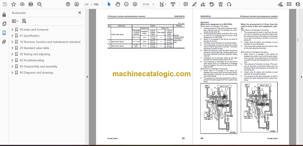
- 10 Structure, function and maintenance standard
- Engine and cooling system
- Engine related parts
- Radiator, oil cooler and aftercooler
- Power train
- Power train
- Swing circle
- Swing machinery
- Final drive
- Sprocket
- Undercarriage and frame
- Track frame and recoil spring
- Idler
- Carrier roller
- Track roller
- Track shoe
- Hydraulic system, Part 1
- Hydraulic equipment layout drawing
- Hydraulic tank and filter
- Hydraulic pump
- Hydraulic system, Part 2
- Control valve
- CLSS
- Functions and operation by valve
- Merge-divider valve
- Attachment circuit selector valve
- Hydraulic drift prevention valve
- Hydraulic system, Part 3
- Valve control
- PPC valve
- Solenoid valve
- PPC accumulator
- Anti-drop valve for boom
- Anti-drop valve for arm
- Return oil filter
- Center swivel joint
- Travel motor
- Swing motor
- Hydraulic cylinder
- Work equipment
- Work equipment
- Dimensions of components
- Cab and its attachments
- Electrical system
- Engine control
- Electronic control system
- Monitor system
- Sensor
- KOMTRAX system
- 20 Standard value table
- Standard service value table
- Standard value table for engine related parts
- Standard value table for chassis related parts
- 30 Testing and adjusting
- Testing and adjusting, Part 1
- Tools for testing, adjusting and troubleshooting
- Sketches of special tools
- Testing engine speed
- Testing air boost pressure
- Testing exhaust gas color
- Adjusting valve clearance
- Testing compression pressure
- Testing blow-by pressure
- Testing engine oil pressure
- Testing fuel pressure
- Handling during cylinder cut-out operation
- Handling during no injection cranking operation
- Testing fuel return rate and leakage
- Bleeding air from fuel circuit
- Checking fuel circuit for leakage
- Testing and adjusting air compressor belt tension
- Replacing fan belt
- Replacing alternator belt
- Testing clearance in swing circle bearings
- Testing and adjusting track shoe tension
- Testing and adjusting oil pressure in work equipment, swing and travel circuit
- Testing and adjusting control circuit oil pressure
- Testing and adjusting pump PC control circuit oil pressure
- Testing and adjusting pump LS control circuit oil pressure
- Testing solenoid valve output pressure
- Testing PPC valve output pressure
- Adjusting play of work equipment and swing PPC valves
- Inspecting locations of hydraulic drift of work equipment
- Releasing remaining pressure from hydraulic system
- Testing oil leakage amount
- Bleeding air from various parts
- Diode inspection procedures
- Installation and adjustment of mirrors
- Testing and adjusting, Part 2
- Special functions of machine monitor
- Testing and adjusting, Part 3
- Handling voltage circuit of engine controller
- Preparation work for troubleshooting of electrical system
- Procedure for testing diodes
- Pm clinic service
- 40 Troubleshooting
- Failure code table and fuse locations
- Failure codes table
- Fuse locations
- General Information on troubleshooting
- Points to remember when troubleshooting
- Sequence of events in troubleshooting
- Checks before troubleshooting
- Checking water pump for water leakage
- Classification and troubleshooting steps
- Information in troubleshooting table
- Possible problems and troubleshooting No.
- Connection table for connector pin numbers
- T- branch box and T- branch adapter table
- Troubleshooting by failure code (Display of code), Part 1
- Failure code [989L00] Engine Controller Lock Caution 1
- Failure code [989M00] Engine Controller Lock Caution 2
- Failure code [989N00] Engine Controller Lock Caution 3
- Failure code [AA10NX] Air cleaner Clogging
- Failure code [AB00KE] Charge Voltage Low
- Failure code [B@BAZG] Eng Oil Press. Low
- Failure code [B@BAZK] Eng Oil Level Low
- Failure code [B@BCNS] Eng. Water Overheat
- Failure code [B@BCZK] Eng Water Level Low
- Failure code [B@HANS] Hydr Oil Overheat
- Failure code [CA111] EMC Critical Internal Failure
- Failure code [CA115] Eng Ne and Bkup Speed Sens Error
- Failure code [CA122] Chg Air Press Sensor High Error
- Failure code [CA123] Chg Air Press Sensor Low Error
- Failure code [CA131] Throttle Sensor High Error
- Failure code [CA132] Throttle Sensor Low Error
- Failure code [CA144] Coolant Temp Sens High Error
- Failure code [CA145] Coolant Temp Sens Low Error
- Failure code [CA153] Chg Air Temp Sensor High Error
- Failure code [CA154] Chg Air Temp Sensor Low Error
- Failure code [CA155] Chg Air Temp High Speed Derate
- Failure code [CA187] Sens Supply 2 Volt Low Error
- Failure code [CA221] Ambient Press Sens High Error
- Failure code [CA222] Ambient Press Sens Low Error
- Failure code [CA227] Sens Supply 2 Volt High Error
- Failure code [CA234] Eng Overspeed
- Failure code [CA238] Ne Speed Sens Supply Volt Error
- Failure code [CA271] IMV/PCV1 Short Error
- Failure code [CA272] IMV/PCV1 Open Error
- Failure code [CA281] Pump Press Balance Error
- Failure code [CA322] Inj #1 (L/B#1) Open/Short Error
- Failure code [CA323] Inj #5 (L/B#5) Open/Short Error
- Failure code [CA324] Inj #3 (L/B#3) Open/Short Error
- Failure code [CA325] Inj #6 (L/B#6) Open/Short Error
- Failure code [CA331] Inj #2 (L/B#2) Open/Short Error
- Failure code [CA332] Inj #4 (L/B#4) Open/Short Error
- Troubleshooting by failure code (Display of code), Part 2
- Failure code [CA342] Calibration Code Incompatibility
- Failure code [CA351] Injectors Drive Circuit Error
- Failure code [CA352] Sens Supply 1 Volt Low Error
- Failure code [CA386] Sens Supply 1 Volt High Error
- Failure code [CA428] Water in Fuel Sensor High Error
- Failure code [CA429] Water in Fuel Sensor Low Error
- Failure code [CA435] Eng Oil Press Sw Error
- Failure code [CA441] Battery Voltage Low Error
- Failure code [CA442] Battery Voltage High Error
- Failure code [CA449] Rail Press Very High Error
- Failure code [CA451] Rail Press Sensor High Error
- Failure code [CA452] Rail Press Sensor Low Error
- Failure code [CA488] Chg Air Temp High Torque Derate
- Failure code [CA553] Rail Press High Error
- Failure code [CA559] Rail Press Low Error
- Failure code [CA689] Eng Ne Speed Sensor Error
- Failure code [CA731] Eng Bkup Speed Sens Phase Error
- Failure code [CA757] All Persistent Data Lost Error
- Failure code [CA778] Eng Bkup Speed Sensor Error
- Failure code [CA1633] KOMNET Datalink Timeout Error
- Failure code [CA2185] Throt Sens Sup Volt High Error
- Failure code [CA2186] Throt Sens Sup Volt Low Error
- Failure code [CA2249] Rail Press Very Low Error
- Failure code [CA2265] Fuel Feed Pump Open Error
- Failure code [CA2266] Fuel Feed Pump Short Error
- Failure code [CA2311] IMV Solenoid Error
- Failure code [CA2555] Grid Htr Relay Volt Low Error
- Failure code [CA2556] Grid Htr Relay Volt High Error
- Failure code [D110KB] Battery Relay Drive S/C
- Failure code [D19JKZ] Personal Code Relay Abnormality
- Failure code [D862KA] GPS Antenna Discon
- Failure code [DA22KK] Pump Solenoid Power Low Error
- Failure code [DA25KP] 5V sensor 1 power abnormality
- Failure code [DA29KQ] Model Selection Abnormality
- Failure code [DA2RMC] Pump Comm. Abnormality
- Failure code [DAF8KB] Short circuit in camera power supply
- Failure code [DAFGMC] GPS Module Error
- Troubleshooting by failure code (Display of code), Part 3
- Failure code [DAFRMC] CAN discon (Monitor detected)
- Failure code [DGH2KB] Hydr Oil Sensor Short
- Failure code [DHPAMA] F Pump Press Sensor Abnormality
- Failure code [DHPBMA] R Pump Press Sensor Abnormality
- Failure code [DHS3MA] Arm Curl PPC Sensor Abnormality
- Failure code [DHS4MA] Bucket Curl PPC Press Sensor Abnormality
- Failure code [DHX1MA] Overload Sensor Abnormality (Analog)
- Failure code [DW43KA] Travel Speed Sol. Open Circuit
- Failure code [DW43KB] Travel Speed Sol. Short Circuit
- Failure code [DW45KA] Swing Brake Sol. Open Circuit
- Failure code [DW45KB] Swing Brake Sol. Short Circuit
- Failure code [DW91KA] Travel Junction Sol. Open Circuit
- Failure code [DW91KB] Travel Junction Sol. Short Circuit
- Failure code [DWA2KA] Attachment Sol Open Circuit
- Failure code [DWA2KB] Attachment Sol Short Circuit
- Failure code [DWJ0KA] Merge-divider Sol. Open Circuit
- Failure code [DWJ0KB] Merge-divider Sol. Short Circuit
- Failure code [DWK0KA] 2-stage Relief Sol. Open Circuit
- Failure code [DWK0KB] 2-stage Relief Sol. Short Circuit
- Failure code [DXA0KA] PC-EPC Sol. Open Circuit
- Failure code [DXA0KB] PC-EPC Sol. Short Circuit
- Failure code [DXE0KA] LS-EPC Sol. Open Circuit
- Failure code [DXE0KB] LS-EPC Sol. Short Circuit
- Failure code [DXE4KA] Service Current EPC Open Circuit
- Failure code [DXE4KB] Service Current EPC Short Circuit
- Failure code [DY20KA] Wiper Working Abnormality
- Failure code [DY20MA] Wiper Parking Abnormality
- Failure code [DY2CKA] Washer Drive Open Circuit
- Failure code [DY2CKB] Washer Drive Short Circuit
- Failure code [DY2DKB] Wiper Drive (Fwd) Short Circuit
- Failure code [DY2EKB] Wiper Drive (Rev) Short Circuit
- Troubleshooting of electrical system (E-mode)
- Before carrying out troubleshooting of electrical system
- Information contained in troubleshooting table
- E-1 Engine does not start
- E-2 Auto-decelerator does not operate
- E-3 Automatic warming-up system does not operate
- E-4 Preheater does not operate
- E-5 All work equipment, swing, and travel mechanism do not move
- E-6 Power maximizing function does not operate
- E-7 Machine monitor does not display at all
- E-8 Machine monitor does not display some items
- E-9 Contents of display by machine monitor are different from applicable machine
- E-10 Fuel level monitor was lighted in red while engine running
- E-11 Engine coolant temperature gauge does not indicate normally
- E-12 Hydraulic oil temperature gauge does not indicate normally
- E-13 Fuel level gauge does not indicate normally
- E-14 Swing lock monitor does not indicate normally
- E-15 When monitor switch is operated, monitor displays nothing
- E-16 Windshield wiper and window washer do not operate
- E-17 Machine push-up function does not operate normally
- E-18 Monitoring function fails to display “boom raise” normally
- E-19 Monitoring function fails to display “boom lower” normally
- E-20 Monitoring function fails to display “arm IN” normally
- E-21 Monitoring function fails to display “arm OUT” normally
- E-22 Monitoring function fails to display “bucket CURL” normally
- E-23 Monitoring function fails to display “bucket DUMP” normally
- E-24 Monitoring function fails to display “swing” normally
- E-25 Monitoring function fails to display “travel” normally
- E-26 Monitoring function fails to display “travel differential pressure” normally
- E-27 Monitoring function fails to display “service” normally
- E-28 KOMTRAX system does not operate normally
- E-29 Air conditioner does not operate
- E-30 Travel alarm does not sound or does not stop sounding
- E-31 Horn does not sound
- Troubleshooting of hydraulic and mechanical system (H-mode)
- System chart for hydraulic and mechanical system
- Information contained in troubleshooting table
- H-1 All work equipment lack power, or travel and swing speeds are slow
- H-2 Engine speed sharply drops or engine stalls
- H-3 No work equipment, swing or travel move
- H-4 Abnormal noise is heard from around hydraulic pump
- H-5 Auto-decelerator does not work
- H-6 Fine control mode does not function or responds slow
- H-7 Boom moves slowly or lacks power
- H-8 Arm moves slowly or lacks power
- H-9 Bucket moves slowly or lacks power
- H-10 Work equipment does not move in its single operation
- H-11 Work equipment has a bit too fast hydraulic drift
- H-12 Work equipment has big time lag
- H-13 Other work equipment moves when relieving single circuit
- H-14 Power max. switch does not operate
- H-15 In compound operation, work equipment with larger load moves slowly
- H-16 In swing + boom RAISE operation, boom moves slowly
- H-17 In swing + travel operation, travel speed drops sharply
- H-18 Machine swerves in travel
- H-19 Machine travels slowly
- H-20 Machine cannot be easily steered or lacks power
- H-21 Travel speed does not shift, or it is too slow or fast
- H-22 Track shoe does not turn (on one side only)
- H-23 Machine does not swing
- H-24 Swing acceleration is poor, or swing speed is slow
- H-25 Excessive overrun when stopping swing
- H-26 There is big shock when stopping swing
- H-27 Large sound is made when upper structure stops swinging.
- H-28 Swing hydraulic drift is too big
- Troubleshooting of engine (S-mode)
- Method of using troubleshooting chart
- S-1 Starting performance is poor
- S-2 Engine does not start
- S-3 Engine does not pick up smoothly
- S-4 Engine stops during operations
- S-5 Engine does not rotate smoothly
- S-6 Engine lacks output (or lacks power)
- S-7 Exhaust smoke is black (incomplete combustion)
- S-8 Oil consumption is excessive (or exhaust smoke is blue)
- S-9 Oil becomes contaminated quickly
- S-10 Fuel consumption is excessive
- S-11 Oil is in coolant (or coolant spurts back or coolant level goes down)
- S-12 Oil pressure drops
- S-13 Oil level rises (Entry of coolant or fuel)
- S-14 Coolant temperature becomes too high (overheating)
- S-15 Abnormal noise is made
- S-16 Vibration is excessive
- 50 Disassembly and assembly
- General information on disassembly andassembly
- How to read this manual
- Coating materials list
- Special tool list
- Sketches of special tools
- Engine and cooling system
- Removal and installation of fuel supply pump assembly
- Removal and installation of engine front seal
- Removal and installation of engine rear seal
- Removal and installation of cylinder head assembly
- Removal and installation of radiator assembly
- Removal and installation of hydraulic oil cooler assembly
- Removal and installation of aftercooler assembly
- Removal and installation of engine and hydraulic pump assembly
- Power train
- Removal and installation of final drive assembly
- Disassembly and assembly of final drive assembly
- Removal and installation of swing motor and swing machinery assembly
- Disassembly and assembly of swing motor and swing machinery assembly
- Removal and installation of swing circle assembly
- Undercarriage and frame
- Disassembly and assembly of carrier roller
- Disassembly and assembly of track roller assembly
- Disassembly and assembly of idler assembly
- Disassembly and assembly of recoil spring
- Removal and installation of sprocket
- Expansion and installation of track shoe assembly
- Removal and installation of revolving frame assembly
- Removal and installation of counterweight assembly
- Hydraulic system
- Removal and installation of center swivel joint assembly
- Disassembly and assembly of center swivel joint assembly
- Removal and installation of hydraulic tank assembly
- Removal and installation of control valve assembly
- Disassembly and assembly of control valve assembly
- Removal and installation of hydraulic pump assembly
- Removal and installation of oil seal in hydraulic pump input shaft
- Disassembly and assembly of work equipment PPC valve assembly
- Disassembly and assembly of travel PPC valve assembly
- Disassembly and assembly of hydraulic cylinder assembly
- Work equipment
- Removal and installation of work equipment assembly
- Removal and installation of anti- drop valve assembly for boom
- Removal and installation of anti- drop valve assembly for arm
- Disassembly and assembly of anti-drop valve assembly
- Cab and its attachments
- Removal and installation of operator's cab assembly
- Removal and installation of operator cab glass (stuck glass)
- Removal and installation of front window assembly
- Removal and installation of floor frame assembly
- Removal and installation of work equipment control lever assembly
- Electrical system
- Removal and installation of air conditioner unit assembly
- Removal and installation of KOMTRAX communication modem assembly
- Removal and installation of monitor assembly
- Removal and installation of pump controller assembly
- Removal and installation of engine controller
- 90 Diagrams and drawings
- Hydraulic diagrams and drawings
- Hydraulic circuit diagram
- Electrical diagrams and drawings
- Electrical circuit diagram
- Connector list and sterogram
Komatsu


