The Komatsu HB365LC-1 Crawler Excavator is a hybrid machine used for heavy digging, loading trucks, and high-production earthmoving where fuel savings matter. People who reach for the Komatsu HB365LC-1 Crawler Excavator Shop Manual (SEN06366-08) are usually shop mechanics, field techs, and serious owner-operators. They’re trying to diagnose hybrid system faults, sort out hydraulic or electrical issues, and do proper teardown and reassembly without guessing.
What this manual helps you do
- Trace hydraulic faults from the pump to the actuators using system layouts and test-point guidance you’d normally see in a dealer workshop.
- Diagnose hybrid system and electrical problems with wiring diagrams, signal flow, and step-by-step troubleshooting logic.
- Follow correct disassembly and reassembly sequences for major components like the engine, swing system, final drives, and hydraulic cylinders.
- Check wear points and adjustment procedures so you know when to repair, when to replace, and how to put it back together so it lasts.
- Verify correct service procedures after a repair, including functional checks that help you avoid repeat callbacks and wasted labor.
Who this is for
This shop manual is aimed at field techs, independent garages, dealer-level mechanics, and fleet maintenance managers handling full repairs. If you only need basic operation or daily service info, you’d be better off with the Operation & Maintenance Manual instead.
FAQ
Q: Is this a PDF I can download and search?
A: Yes, it’s a digital PDF you can download, search by keyword, and print specific sections for use in the shop.
Q: Does it go deep enough for full component rebuilds?
A: Yes, this kind of Komatsu shop manual usually covers teardown, inspection points, and reassembly procedures for workshop-level repairs.
Q: How do I know if it matches my exact HB365LC-1 variant?
A: Check your machine plate against the model HB365LC-1 and confirm the book reference SEN06366-08; if those match, this is more or less the right shop manual.
Bottom line: If you’re actually repairing or troubleshooting a Komatsu HB365LC-1, this shop manual is the right tool; if you just run the machine, keep looking for the operator’s manual instead.
📘 Show Index
Table of Contents:
- 00 Index and foreword
- Index
- Foreword, safety and general information
- Important safety notice (Hybrid)
- How to read the shop manual
- Explanation of terms for maintenance standard
- Handling equipment of fuel system devices
- Handling of intake system parts
- Handling of hydraulic equipment
- Method of disconnecting and connecting of push-pull type coupler
- Handling of electrical equipment
- How to read electric wire code (Hybrid)
- Precautions when performing operation
- Practical use of KOMTRAX
- Handling hybrid components and high voltage wiring harness
- Standard tightening torque table
- List of abbreviation
- Conversion table
- 01 Specification
- Table of contents
- Specifications
- Specification drawing
- Working range drawings
- Specifications
- Weight table
- Table of fuel, coolant, and lubricants
- 10 Structure and function
- Table of contents
- Engine and cooling system
- Engine related parts
- VGT
- EGR system piping drawing
- EGR system circuit diagram
- EGR valve
- EGR cooler
- Cooling system
- Hybrid system
- Outline of hybrid system
- Configuration of hybrid system
- Protective function of hybrid component
- Protection function for workers when disassembling hybrid component
- Cooling system of hybrid component
- Interlock function
- Motor-generator
- Electric swing motor
- Electric control unit
- High voltage wiring harness (power cable)
- Water pump
- Power train
- Power train system
- Swing circle
- Swing machinery with swing brake
- Final drive
- Undercarriage and frame
- Track frame and idler cushion
- Hydraulic system
- Hydraulic component layout
- Valve control
- Hydraulic tank
- CLSS
- Main pump
- Control valve
- Travel motor
- PPC valve
- Solenoid valve
- Attachment circuit selector valve
- Center swivel joint
- Accumulator
- Work equipment
- Electrical system
- Electrical control system
- System component parts
- Machine monitor system
- KOMTRAX system (GPRS type)
- KOMTRAX system (Orbcomm type)
- Sensor
- 20 Standard value tables
- Table of contents
- Standard service value table
- Standard value table for engine
- Standard value table for machine
- 30 Testing and adjusting
- Table of contents
- Related information on testing and adjusting
- Tools for testing and adjusting
- Sketch of tools for testing and adjusting
- Engine and cooling system
- Testing engine speed
- Testing boost pressure
- Testing exhaust gas color
- Testing and adjusting valve clearance
- Testing compression pressure
- Testing blowby pressure
- Testing engine oil pressure
- Testing EGR valve and VGT oil pressures
- Testing fuel pressure
- Testing fuel discharge, return and leakage
- Bleeding air from fuel system
- Testing fuel circuit for leakage
- Handling cylinder cutout mode operation
- Handling no-injection cranking operation
- Checking and adjusting air conditioner compressor belt tension
- Replacing fan belt
- Replacing alternator belt
- Hybrid system
- Precautions related to hybrid equipment
- Bleeding air from hybrid cooling system
- Testing water pressure of hybrid coolant
- Testing swing parking brake
- Cleaning and replacing oil filter of electric swing motor
- Testing operation of swing emergency stop switch
- Power train
- Testing swing circle bearing clearance
- Undercarriage and frame
- Testing and adjusting track tension
- Hydraulic system
- Releasing remaining pressure from hydraulic circuit
- Testing oil pressure of control circuit
- Testing and adjusting oil pressure in work equipment and travel circuits
- Testing and adjusting oil pressure in pump PC control circuit
- Testing and adjusting oil pressure in pump LS control circuit
- Testing outlet pressure of solenoid valve
- Testing PPC valve outlet pressure
- Adjusting play of work equipment and swing PPC valves
- Testing pump swash plate sensor
- Isolating the parts causing hydraulic drift in work equipment
- Testing oil leakage
- Bleeding air from hydraulic circuit
- Cab and its attachments
- Checking cab tipping stopper
- Adjusting mirrors
- Electrical system
- Special functions of machine monitor
- KOMTRAX terminal start-up procedure
- Adjusting rearview camera angle
- Handling voltage circuit of engine controller
- Testing diodes
- Pm clinic
- 40 Troubleshooting
- Table of contents
- Related information on troubleshooting
- Troubleshooting points
- Sequence of events in troubleshooting
- Checks before troubleshooting
- Inspection procedure before troubleshooting
- Preparation work for troubleshooting of electrical system
- Classification and procedures for troubleshooting
- Symptom and troubleshooting numbers
- Information in troubleshooting table
- Troubleshooting method for open circuit in wiring harness of pressure sensor system
- Connector list and layout
- Connector contact identification
- T-branch box and T-branch adapter table
- Fuse location table
- Failure codes table
- Troubleshooting by failure code (Display of code)
- Failure code [879AKA] A/C Inner Sensor Open Circuit
- Failure code [879AKB] A/C Inner Sensor Short Circuit
- Failure code [879BKA] A/C Outer Sensor Open Circuit
- Failure code [879BKB] A/C Outer Sensor Short Circuit
- Failure code [879CKA] Ventilating Sensor Open Circuit
- Failure code [879CKB] Ventilating Sensor Short Circuit
- Failure code [879DKZ] Sunlight Sensor Open Or Short Circuit
- Failure code [879EMC] Ventilation Damper Abnormality
- Failure code [879FMC] Air Mix Damper Abnormality
- Failure code [879GKX] Refrigerant Abnormality
- Failure code [989L00] Engine Controller Lock Caution 1
- Failure code [989M00] Engine Controller Lock Caution 2
- Failure code [989N00] Engine Controller Lock Caution 3
- Failure code [AA10NX] Air Cleaner Clogging
- Failure code [AB00KE] Charge Voltage Low
- Failure code [B@BAZG] Eng Oil Press Low
- Failure code [B@BAZK] Eng Oil Level Low
- Failure code [B@BCNS] Eng Water Overheat
- Failure code [B@BCZK] Eng Water Level Low
- Failure code [B@HANS] Hyd Oil Overheat
- Failure code [CA115] Eng Ne and Bkup Speed Sens Error
- Failure code [CA122] Chg Air Press Sensor High Error
- Failure code [CA123] Chg Air Press Sensor Low Error
- Failure code [CA131] Throttle Sensor High Error
- Failure code [CA132] Throttle Sensor Low Error
- Failure code [CA144] Coolant Temp Sens High Error
- Failure code [CA145] Coolant Temp Sens Low Error
- Failure code [CA153] Chg Air Temp Sensor High Error
- Failure code [CA154] Chg Air Temp Sensor Low Error
- Failure code [CA187] Sensor 2 Supply Volt Low Error
- Failure code [CA221] Ambient Press Sensor High Error
- Failure code [CA222] Ambient Press Sens Low Error
- Failure code [CA227] Sensor 2 Supply Volt High Error
- Failure code [CA234] Eng Overspeed
- Failure code [CA238] Ne Speed Sensor Supply Volt Error
- Failure code [CA239] Ne Speed Sens Supply Volt High Error
- Failure code [CA271] IMV/PCV1 Short Error
- Failure code [CA272] IMV/PCV1 Open Error
- Failure code [CA281] Pump Press Balance Error
- Failure code [CA295] Ambient Press Sens In Range Error
- Failure code [CA322] Inj #1(L#1) Open/Short Error
- Failure code [CA323] Inj #5(L#5) Open/Short Error
- Failure code [CA324] Inj #3(L#3) Open/Short Error
- Failure code [CA325] Inj #6(L#6) Open/Short Error
- Failure code [CA331] Inj #2(L#2) Open/Short Error
- Failure code [CA332] Inj #4(L#4) Open/Short Error
- Failure code [CA343] ECM Critical Internal Failure
- Failure code [CA351] Injectors Drive Circuit Error
- Failure code [CA352] Sensor 1 Supply Volt Low Error
- Failure code [CA356] Mass Air Flow Sensor High Error
- Failure code [CA357] Mass Air Flow Sensor Low Error
- Failure code [CA386] Sensor 1 Supply Volt High Error
- Failure code [CA428] Water in Fuel Sensor High Error
- Failure code [CA429] Water in Fuel Sensor Low Error
- Failure code [CA435] Eng Oil Press Sw Error
- Failure code [CA441] Battery Voltage Low Error
- Failure code [CA442] Battery Voltage High Error
- Failure code [CA449] Rail Press Very High Error
- Failure code [CA451] Rail Press Sensor High Error
- Failure code [CA452] Rail Press Sensor Low Error
- Failure code [CA488] Chg Air Temp High Torque Derate
- Failure code [CA515] Rail Press Sens Sup Volt High Error
- Failure code [CA516] Rail Press Sens Sup Volt Low Error
- Failure code [CA553] Rail Press High Error
- Failure code [CA559] Rail Pump Press Low Error
- Failure code [CA595] Turbo Speed High Error 2
- Failure code [CA687] Turbo Speed Low Error
- Failure code [CA689] Eng Ne Speed Sensor Error
- Failure code [CA691] Intake Air Temp Sens High Error
- Failure code [CA692] Intake Air Temp Sens Low Error
- Failure code [CA697] ECM Internal Temp Sensor High Error
- Failure code [CA698] ECM Int Temp Sensor Low Error
- Failure code [CA731] Eng Bkup Speed Sens Phase Error
- Failure code [CA778] Eng Bkup Speed Sensor Error
- Failure code [CA1117] Persistent Data Lost Error
- Failure code [CA1695] Sensor 5 Supply Volt High Error
- Failure code [CA1696] Sensor 5 Supply Volt Low Error
- Failure code [CA2185] Throt Sensor Sup Volt High Error
- Failure code [CA2186] Throt Sensor Sup Volt Low Error
- Failure code [CA2249] Rail Press Very Low Error
- Failure code [CA2265] Fuel Feed Pump Open Error
- Failure code [CA2266] Fuel Feed Pump Short Error
- Failure code [CA2271] EGR Valve Pos Sens High Error
- Failure code [CA2272] EGR Valve Pos Sens Low Error
- Failure code [CA2288] Turbo Speed High Error 1
- Failure code [CA2311] IMV Solenoid Error
- Failure code [CA2349] EGR Valve Solenoid Open Error
- Failure code [CA2353] EGR Valve Solenoid Short Error
- Failure code [CA2357] EGR Valve Servo Error
- Failure code [CA2373] Exhaust Manifold Press Sens High Error
- Failure code [CA2374] Exhaust Manifold Press Sens Low Error
- Failure code [CA2375] EGR Orifice Temp Sens High Error
- Failure code [CA2376] EGR Orifice Temp Sens Low Error
- Failure code [CA2381] VGT Pos Sens High Error
- Failure code [CA2382] VGT Pos Sens Low Error
- Failure code [CA2383] VGT Solenoid Open Error
- Failure code [CA2386] VGT Solenoid Short Error
- Failure code [CA2387] VGT Servo Error
- Failure code [CA2555] Grid Htr Relay Volt Low Error
- Failure code [CA2556] Grid Htr Relay Volt High Error
- Failure code [CA2961] EGR Orifice Temp High Error 1
- Failure code [CA2973] Chg Air Press Sensor In Range Error
- Failure code [CA3419] Mass Air Flow Sensor Sup Volt High Error
- Failure code [CA3421] Mass Air Flow Sensor Sup Volt Low Error
- Failure code [CA3741] Rail Press Valve Trip Error
- Failure code [D110KB] Battery Relay Drive Short Circuit
- Failure code [D19JKZ] Personal Code Relay Abnormality
- Failure code [D811MC] KOMTRAX Error
- Failure code [D862KA] GPS Antenna Open Circuit
- Failure code [D8AQKR] CAN2 Discon (KOMTRAX)
- Failure code [DA20MC] Pump Controller Malfunction
- Failure code [DA22KK] Pump Solenoid Power Low Error
- Failure code [DA25KP] 5V Sensor 1 Power Abnormality
- Failure code [DA29KQ] Model Selection Abnormality
- Failure code [DA2QKR] CAN2 Discon (Pump Con)
- Failure code [DA2RKR] CAN1 Discon (Pump Con)
- Failure code [DAF0MB] Monitor ROM Abnormality
- Failure code [DAF0MC] Monitor Error
- Failure code [DAF8KB] Camera Power Supply Short Circuit
- Failure code [DAF9KQ] Model Selection Abnormality
- Failure code [DAFGMC] GPS Module Error
- Failure code [DAFQKR] CAN2 Discon (Monitor)
- Failure code [DAZ9KQ] AC Model Selection Abnormality
- Failure code [DAZQKR] CAN2 Discon (Aircon ECU)
- Failure code [DB2QKR] CAN2 Discon (Engine Con)
- Failure code [DB2RKR] CAN1 Discon (Engine Con)
- Failure code [DGH2KB] Hyd Oil Sensor Short Circuit
- Failure code [DHA4KA] Air Cleaner Clogging Sensor Open Circuit
- Failure code [DHPAMA] F Pump Press Sensor Abnormality
- Failure code [DHPBMA] R Pump Press Sensor Abnormality
- Failure code [DHS3MA] Arm Curl PPC Press Sensor Abnormality
- Failure code [DHS4MA] Bucket Curl PPC Press Sensor Abnormality
- Failure code [DHS8MA] Boom Raise PPC Press Sensor Abnormality
- Failure code [DHS9MA] Boom Lower PPC Press Sensor Abnormality
- Failure code [DHSAKZ] Swing RH PPC Press Sensor Abnormality
- Failure code [DHSBKZ] Swing LH PPC Press Sensor Abnormality
- Failure code [DHSCMA] Arm Dump PPC Press Sensor Abnormality
- Failure code [DHSDMA] Bucket Dump PPC Press Sensor Abnormality
- Failure code [DHSFMA] Travel Fwd LH PPC Press Sensor Abnormality
- Failure code [DHSGMA] Travel Fwd RH PPC Press Sensor Abnormality
- Failure code [DHSHMA] Travel Rev LH PPC Press Sensor Abnormality
- Failure code [DHSJMA] Travel Rev RH PPC Press Sensor Abnormality
- Failure code [DHVAKZ] HYB Swng-R PPC Pr. Sen. Opn/Short Cirt.
- Failure code [DHVAL8] HYB Swing-R PPC Pr. Sen. Signal Mismatch
- Failure code [DHVAMA] HYB Swing-R PPC Sensor Malfunction
- Failure code [DHVBKZ] HYB Swng-L PPC Pr. Sen. Opn/Short Cir.
- Failure code [DHVBL8] HYB Swing-L PPC Pr. Sen. Signal Mismatch
- Failure code [DHVBMA] HYB Swing-L PPC Sensor Malfunction
- Failure code [DKR0MA] F Pump Swash Plate Sensor Abnormality
- Failure code [DKR1MA] R Pump Swash Plate Sensor Abnormality
- Failure code [DR21KX] Camera 2 Picture Rev. Drive Abnormality
- Failure code [DR31KX] Camera 3 Picture Rev. Drive Abnormality
- Failure code [DV20KB] Travel Alarm Short Circuit
- Failure code [DW43KA] Travel Speed Sol Open Circuit
- Failure code [DW43KB] Travel Speed Sol Short Circuit
- Failure code [DW45KA] Swing Brake Sol Open Circuit
- Failure code [DW45KB] Swing Brake Sol Short Circuit
- Failure code [DW45KK] Swing Brake Sol. Valve Low Sup. Voltage
- Failure code [DW45KY] Swing Brake Sol. Val. Pow. Short Cir.
- Failure code [DW91KA] Travel Junction Sol Open Circuit
- Failure code [DW91KB] Travel Junction Sol Short Circuit
- Failure code [DWA2KA] Attachment Sol Open Circuit
- Failure code [DWA2KB] Attachment Sol Short Circuit
- Failure code [DWK0KA] 2-Stage Relief Sol Open Circuit
- Failure code [DWK0KB] 2-Stage Relief Sol Short Circuit
- Failure code [DWK2KA] Variable Back Press Sol Open Circuit
- Failure code [DWK2KB] Variable Back Press Sol Short Circuit
- Failure code [DXA8KA] PC-EPC (F) Sol Open Circuit
- Failure code [DXA8KB] PC-EPC (F) Sol Short Circuit
- Failure code [DXA9KA] PC-EPC (R) Sol Open Circuit
- Failure code [DXA9KB] PC-EPC (R) Sol Short Circuit
- Failure code [DXE0KA] LS-EPC Sol Open Circuit
- Failure code [DXE0KB] LS-EPC Sol Short Circuit
- Failure code [DXE4KA] Attachment Flow EPC Open Circuit
- Failure code [DXE4KB] Attachment Flow EPC Short Circuit
- Failure code [DXE5KA] Merge-divide Main Sol Open Circuit
- Failure code [DXE5KB] Merge-divide Main Sol Short Circuit
- Failure code [DXE6KA] Merge-divide LS Sol Open Circuit
- Failure code [DXE6KB] Merge-divide LS Sol Short Circuit
- Failure code [DY20KA] Wiper Working Abnormality
- Failure code [DY20MA] Wiper Parking Abnormality
- Failure code [DY2CKB] Washer Drive Short Circuit
- Failure code [DY2DKB] Wiper Drive (Fwd) Short Circuit
- Failure code [DY2EKB] Wiper Drive (Rev) Short Circuit
- Failure code [GA****] Precautions for hybrid components and troubleshooting of high voltage parts
- Failure code [GA——] Table and check sheet of monitoring items on hybrid components
- Failure code [GA00NS] HYB Equipment Overheat
- Failure code [GA01KA] Power Cable Interlock Open Circuit
- Failure code [GA02KZ] DC Line Open & Short Circuit
- Failure code [GA04KG] Abnormal DC HW Volt. Before Booster
- Failure code [GA05KG] Abnormal DC SW Volt. Before Booster
- Failure code [GA05KP] Low DC SW Output Volt. Bef. Booster
- Failure code [GA06KZ] DC Vlt. Sen. Opn./Shrt.Cir. Bef. Booster
- Failure code [GA08KG] Abnorm. DC HW Volt. After Booster
- Failure code [GA09KG] Abnorm. DC SW Volt. After Booster
- Failure code [GA09KP] Low DC SW Output Volt. After Booster
- Failure code [GA0AKZ] DC Vlt. Sen. Op./Shrt Cir. Aft. Booster
- Failure code [GA0BKZ] AC Line Open & Short Circuit
- Failure code [GA10MC] HYB Controller Error
- Failure code [GA12NK] High-Voltage Line Start-up Failure
- Failure code [GA12NL] High-Voltage Line Discharge Failure
- Failure code [GA13MC] HYB Control. Sen. Power Sup. Failure
- Failure code [GA15KZ] HYB Cont. Bad Insul. Sen. Opn/Short. Cir
- Failure code [GA17KR] Gen. Mot. Drv. Communication Failure
- Failure code [GA17KY] Gen. Mot Dr. Power Line Short Circuit
- Failure code [GA17MB] Gen. Mot. Drv. Function Degraded
- Failure code [GA18MC] Gen. Mo.Dr. Excite. Pow. Sup. Failure
- Failure code [GA19KR] Gen. Motor Driver Sub-CPU Comm. Failure
- Failure code [GA19KT] Int. Abnorm. Gen. Mot. Drv. Sub-CPU Con.
- Failure code [GA19MA] Gen. Mot. Drv. Sub-CPU Malfunction
- Failure code [GA1BMA] Gen. Mot. Dr. DC Vlt. Sens. Malfunction
- Failure code [GA1FKR] Swing Mot. Drv. Communication Failure
- Failure code [GA1FMA] Abnormal Swing Motor Driver
- Failure code [GA1GKR] Swg Mot. Driver Sub-CPU Comm. Failure
- Failure code [GA1GKT] Swing Mot. Drv. Sub-CPU Cont. Abnormal
- Failure code [GA1GMA] Swing Motor Drv. Sub-CPU Malfunction
- Failure code [GA1GMB] Swing Mot. Drv. Sub-CPU Funct. Degraded
- Failure code [GA1HKZ] Swg Mot. Dr. Ph-U Tem. Sens Opn/Shrt Cir
- Failure code [GA1JKZ] Swg Mot. Dr. Ph-V Tem. Sens Opn/Shrt Cir
- Failure code [GA1KKZ] Swg Mot. Dr. Ph-W Tem. Sens Opn/Shrt Cir
- Failure code [GA1LKZ] Swg Mot. Dr. Current. Sens. Opn/Shrt Cir
- Failure code [GA1MKZ] Swg Mot. Dr. DC Vlt. Sen. Opn/Shrt Cir.
- Failure code [GA1NNS] Swing Motor Driver IGBT Overheat
- Failure code [GA1SFS] Contactor Locked
- Failure code [GA1SMC] Contactor Failure
- Failure code [GA1TKP] Capacitor Low Output Voltage
- Failure code [GA1TNS] Capacitor Overheat
- Failure code [GA1UKZ] Capacitor Temp. Sensor Opn/short Cir.
- Failure code [GA1VFS] Capacitor Contactor Locked
- Failure code [GA1VMC] Capacitor Contactor Failure
- Failure code [GA1XKZ] Boost. Ind. Temp. Sens. Open/Shrt. Circ.
- Failure code [GA1YNS] Booster Inductor Overheat
- Failure code [GA1ZKZ] Booster IGBT Temp. Sens. Opn/Shrt. Circ.
- Failure code [GA1ZNS] Booster IGBT Temp. Sens. Overheat
- Failure code [GA21KB] Booster IGBT Short Circuit
- Failure code [GA22NS] Booster IGBT Junction Overheat
- Failure code [GA23KZ] Gen. Mot. Dr. Temp. Sen.0 Opn/Short Cir.
- Failure code [GA24KZ] Gen. Mot. Dr. Temp. Sen.1 Opn/Short Cir.
- Failure code [GA25MA] Gen. Motor Driver IGBT 0 Abnormality
- Failure code [GA25NS] Gen. Motor Driver IGBT 0 Overheat
- Failure code [GA26MA] Gen. Motor Driver IGBT 1 Abnormality
- Failure code [GA26NS] Gen. Motor Driver IGBT 1 Overheat
- Failure code [GA27KZ] DC Cur. Sens. Bef. Booster Opn/Short Cir
- Failure code [GA28KZ] DC Cur. Sens. Aft. Booster Opn/Short Cir
- Failure code [GA2QKR] CAN2 Discon (Hyb Con)
- Failure code [GA2RKR] CAN1 Discon (Hyb Con)
- Failure code [GA60MC] Generator Motor Failure
- Failure code [GA60N1] Generator Motor Overrun
- Failure code [GA61KZ] Gen. Motor Temp. Sens. Opn/Short Cir.
- Failure code [GA61NS] Generator Motor Temp. Sensor Overheat
- Failure code [GA62KY] Gen. Mot. Ph-A Cur. Sen. Power Short Cir
- Failure code [GA62KZ] Gen. Mot. Ph-A Cur. Sen. Open/Short Cir
- Failure code [GA62MA] Gen. Mot. Ph-A Current Sen. Malfunction
- Failure code [GA63KY] Gen. Mot. Ph-B Cur. Sen. Power Short Cir
- Failure code [GA63KZ] Gen. Mot. Ph-B Cur. Sen. Open/Short Cir
- Failure code [GA63MA] Gen. Mot. Ph-B Current Sen. Malfunction
- Failure code [GA64KY] Gen. Mot. Ph-C Cur. Sen. Power Short Cir
- Failure code [GA64KZ] Gen. Mot. Ph-C Cur. Sen. Open/Short Cir
- Failure code [GA64MA] Gen. Mot. Ph-C Current Sen. Malfunction
- Failure code [GA70KB] HYB Swing Motor Short Circuit
- Failure code [GA70MD] HYB Swing Motor Defective Stirr. Motion
- Failure code [GA70NS] HYB Swing Motor Overheat
- Failure code [GA71KZ] HYB Swing Mot. Temp. Sens. Opn/Shrt Cir.
- Failure code [GA72MA] HYB Swing Motor Resolver Malfunction
- Failure code [GA72MC] HYB Swing Motor Resolver Defect Op.
- Failure code [GA81KZ] Swing Motor Power Cable Opn/Shrt Circ.
- Failure code [GAA0KB] HYB Con. Battery Relay Drive Short Cir.
- Failure code [GAA100] Swing Emergency Stop Operation
- Failure code [GAA2KB] Swing Brake Sol. Supply Line Short Cir.
- Troubleshooting of electrical system (E-mode)
- E-1 Engine does not start (Engine does not crank)
- E-2 Manual preheating system does not work
- E-3 Automatic preheating system does not work
- E-4 While preheating is working, preheating monitor does not light up
- E-5 When starting switch is turned to ON position, machine monitor displays nothing
- E-6 While starting switch is turned to ON position (with engine stopped), engine oil level monitor lights up in yellow
- E-7 While starting switch is turned to ON position (with engine stopped), radiator coolant level monitor lights up in yellow
- E-8 Engine coolant temperature monitor lights up in white while engine is running
- E-9 Hydraulic oil temperature monitor lights up in white while engine is running
- E-10 Charge level monitor lights up in red while engine is running
- E-11 Fuel level monitor lights up in red while engine is running
- E-12 Air cleaner clogging monitor lights up in yellow while engine is running
- E-13 Engine coolant temperature monitor lights up in red while engine is running
- E-14 Hydraulic oil temperature monitor lights up in red while engine is running
- E-15 Engine oil pressure monitor lights up in red while engine is running
- E-16 Fuel gauge display does not move from minimum or maximum
- E-17 Fuel gauge indicates incorrect amount
- E-18 Engine coolant temperature gauge display does not move from minimum or maximum
- E-19 Engine coolant temperature gauge indicates incorrect temperature
- E-20 Hydraulic oil temperature gauge display does not move from minimum or maximum
- E-21 Hydraulic oil temperature gauge indicates incorrect temperature
- E-22 Hybrid temperature gauge does not indicate correct temperature
- E-23 Some areas of machine monitor screen are not displayed
- E-24 Function switch does not work
- E-25 Automatic warm-up system does not operate (in cold season)
- E-26 Auto-deceleration monitor does not light up, or does not go out, while auto-deceleration switch is operated
- E-27 Auto-deceleration function does not operate or is not canceled while lever is operated
- E-28 Working mode selection screen is not displayed while working mode selector switch is operated
- E-29 Setting of engine and hydraulic pump is not changed while working mode is changed
- E-30 Travel speed monitor does not change when travel speed switch is operated
- E-31 Travel speed does not change while travel speed selection is changed
- E-32 Alarm buzzer does not stop sounding
- E-33 Service meter is not displayed, while starting switch is in OFF position
- E-34 Service mode cannot be selected
- E-35 Any of work equipment, swing and travel does not work
- E-36 Any of work equipment, swing and travel cannot be locked
- E-37 Upper structure does not swing while swing parking brake cancel switch is set to CANCEL position
- E-38 Swing brake does not operate while swing parking brake cancel switch is set to NORMAL position
- E-39 One-touch power maximizing function does not operate properly, or indicator is not displayed on monitor
- E-40 One-touch power maximizing function cannot be canceled
- E-41 Alarm does not sound during travel
- E-42 Alarm does not stop sounding while machine is stopped
- E-43 Horn does not sound
- E-44 Horn does not stop sounding
- E-45 Wiper monitor does not light up, or does not go out, while wiper switch is operated
- E-46 Wiper does not operate while wiper switch is operated
- E-47 Window washer does not operate while window washer switch is operated
- E-48 Boom LOWER is not displayed correctly with monitoring function
- E-49 Arm OUT is not displayed correctly with monitoring function
- E-50 Arm IN is not displayed correctly with monitoring function
- E-51 Boom RAISE is not displayed correctly with monitoring function
- E-52 Bucket CURL is not displayed correctly with monitoring function
- E-53 Bucket DUMP is not displayed correctly with monitoring function
- E-54 Swing is not displayed correctly with monitoring function
- E-55 Travel is not displayed correctly with monitoring function
- E-56 Service is not displayed correctly with monitoring function
- E-57 Attachment hydraulic circuit cannot be changed
- E-58 KOMTRAX system does not operate normally
- E-59 Machine push-up function is not canceled
- E-60 Machine push-up function does not operate
- Troubleshooting of hydraulic and mechanical system (H-mode)
- Information described in troubleshooting table (H-mode)
- System chart of hydraulic and mechanical systems
- Failure mode and cause table
- H-1 All of work equipments and travel operations lack speed or power
- H-2 Engine speed drops significantly or engine stalls
- H-3 Any of work equipment and travel does not work
- H-4 Unusual sound is heard from around hydraulic pump
- H-5 Fine control performance or response is poor
- H-6 Boom speed or power is low
- H-7 Arm speed or power is low
- H-8 Bucket speed or power is low
- H-9 Work equipment does not move in single operation
- H-10 Hydraulic drift of boom is large
- H-11 Hydraulic drift of arm is large
- H-12 Hydraulic drift of bucket is large
- H-13 Time lag of work equipment is large
- H-14 When part of work equipment is relieved singly, other parts of work equipment move
- H-15 One-touch power maximizing function does not work
- H-16 Machine push up function does not work
- H-17 In combined operation of work equipment, equipment having heavier load moves slower
- H-18 Machine does not travel straight
- H-19 Travel speed is slow
- H-20 Machine is hard to steer or travel power is low
- H-21 Travel speed does not change, or travel speed is too slow or fast
- H-22 One of tracks does not run
- H-23 Upper structure does not swing to the right or left
- H-24 Upper structure swing only to the right or left
- H-25 Swing acceleration or swing speed is low in both directions (right and left)
- H-26 Swing acceleration performance is poor or swing speed is slow in only one direction
- H-27 Upper structure overruns excessively when it stops swinging (both right and left)
- H-28 Upper structure overruns excessively when it stops swinging (either right or left)
- H-29 Shock is large when upper structure stops swinging
- H-30 Large unusual noise is heard when upper structure stops swinging
- H-31 Swing drift on a slope is large while swing parking brake is applied
- H-32 Swing drift on a slope is large while swing parking brake is released
- H-33 Attachment hydraulic circuit cannot be changed while attachment is installed
- H-34 Oil flow in attachment circuit cannot be controlled
- Troubleshooting of engine (S-mode)
- Information contained in troubleshooting table (S mode)
- S-1 Engine does not crank when starting switch is turned to START position
- S-2 The engine cranks but exhaust smoke does not come out
- S-3 Fuel is being injected but engine does not start (incomplete combustion: engine cranks but does not start)
- S-4 Engine startability is poor
- S-5 Engine does not pick up smoothly
- S-6 Engine stops during operation
- S-7 Engine runs rough or is unstable
- S-8 Engine lacks power
- S-9 Exhaust smoke is black
- S-10 Engine oil consumption is excessive
- S-11 Oil becomes contaminated quickly
- S-12 Fuel consumption is excessive
- S-13 Oil is in coolant (or coolant spurts or coolant level goes down)
- S-14 Oil pressure drops
- S-15 Fuel mixes into engine oil
- S-16 Water mixes into engine oil (milky)
- S-17 Coolant temperature rises too high (overheating)
- S-18 Unusual noise is heard
- S-19 Vibration is excessive
- S-20 Air cannot be bled from fuel circuit
- Troubleshooting for hybrid systems (Y mode)
- Precautions related to hybrid equipment
- Y-1 Hybrid monitor does not go out
- Y-2 Machine does not swing
- Y-3 Swing acceleration or swing speed is low
- Y-4 Upper structure overruns excessively when it stops swinging
- Y-5 Shock is large when upper structure stops swinging
- Y-6 Large unusual noise is heard when upper structure stops swinging
- Y-7 Swing drift on a slope is large
- Y-8 Electric swing motor temperature increases abnormally
- Y-9 Motor-generator temperature increases abnormally
- Y-10 Inverter temperature increases abnormally
- Y-11 Capacitor temperature increases abnormally
- 50 Disassembly and assembly
- Table of contents
- Related information on disassembly and assembly
- How to read this manual
- Precautions related to hybrid equipment
- Coating materials list
- Special tools list
- Sketches of special tools
- Engine and cooling system
- Removal and installation of supply pump assembly
- Removal and installation of injector assembly
- Removal and installation of cylinder head assembly
- Removal and installation of radiator assembly
- Removal and installation of hydraulic oil cooler assembly
- Removal and installation of aftercooler core
- Removal and installation of engine, motor-generator, and main pump assembly
- Removal and installation of fan belt
- Removal and installation of alternator belt
- Removal and installation of engine front oil seal
- Removal and installation of engine rear oil seal
- Removal and installation of fuel tank assembly
- Removal and installation of air cleaner assembly
- Removal and installation of air conditioner compressor assembly
- Removal and installation of air conditioner condenser assembly
- Removal and installation of EGR (Exhaust Gas Recirculation) valve assembly
- Removal and installation of EGR (Exhaust Gas Recirculation) cooler assembly
- Hybrid system
- Draining coolant, refilling with coolant, and bleeding air for hybrid system
- Removal and installation of hybrid system radiator assembly
- Removal and installation of hybrid system water pump assembly
- Removal and installation of inverter assembly
- Removal and installation of inverter and capacitor assembly
- Procedure for draining and refilling generator lubricating oil
- Removal and installation of motor-generator and housing assembly
- Removal and installation of electric swing motor assembly
- Power train system
- Removal and installation of travel motor and final drive assembly
- Disassembly and assembly of final drive assembly
- Removal and installation of electric swing motor and swing machinery assembly
- Disassembly and assembly of swing machinery assembly
- Removal and installation of swing circle assembly
- Undercarriage and frame
- Separation and connection of track shoe assembly
- Removal and installation of sprocket
- Removal and installation of idler and idler cushion assembly
- Disassembly and assembly of idler
- Disassembly and assembly of idler cushion assembly
- Disassembly and assembly of track roller assembly
- Disassembly and assembly of carrier roller assembly
- Removal and installation of revolving frame assembly
- Removal and installation of counterweight assembly
- Hydraulic system
- Removal and installation of center swivel joint assembly
- Disassembly and assembly of center swivel joint assembly
- Removal and installation of hydraulic tank assembly
- Removal and installation of main pump assembly
- Removal and installation of control valve assembly
- Disassembly and assembly of control valve assembly
- Procedure for replacing pressure compensation valve seal
- Assembly of control valve assembly
- Disassembly and assembly of work equipment PPC valve assembly
- Disassembly and assembly of travel PPC valve assembly
- Work equipment
- Removal and installation of bucket assembly
- Removal and installation of arm assembly
- Removal and installation of work equipment assembly
- Disassembly and assembly of work equipment cylinder assembly
- Cab and its attachments
- Removal and installation of operator's cab assembly
- Removal and installation of operator's cab glass (adhered glass)
- Removal and installation of front window assembly
- Removal and installation of floor frame assembly
- Removal and installation of air conditioner unit assembly
- Removal and installation of operator's seat
- Removal and installation of seat belt
- Removal and installation of work equipment control lever assembly
- Removal and installation of front wiper assembly
- Electrical system
- Removal and installation of engine controller assembly
- Removal and installation of pump controller assembly
- Removal and installation of machine monitor assembly
- Removal and installation of pump swash plate sensor
- Removal and installation of KOMTRAX terminal assembly
- 60 Maintenance standard
- Table of contents
- Engine and cooling system
- Engine mount
- Cooling system
- Power train system
- Swing circle
- Swing machinery with swing brake
- Final drive
- Sprocket
- Undercarriage and frame
- Track frame and idler cushion
- Idler
- Track roller
- Carrier roller
- Track shoe
- Hydraulic system
- Hydraulic tank
- Main pump
- Control valve
- Travel motor
- PPC valve
- Solenoid valve
- Attachment circuit selector valve
- Center swivel joint
- Work equipment
- Work equipment
- Work equipment cylinder
- 80 Appendix
- Table of contents
- Air conditioner components
- Precautions for refrigerant
- Air conditioner component
- Configuration and function of refrigeration cycle
- Outline of refrigeration cycle
- Air conditioner unit
- Dual pressure switch
- Air conditioner controller
- Compressor
- Condenser
- Receiver drier
- Sunlight sensor
- Outer temperature sensor (outside air temperature sensor)
- Procedure for testing and troubleshooting
- Circuit diagram and arrangement of connector pins
- System diagram
- Parts and connectors layout
- Testing air leakage (duct)
- Testing with self-diagnosis function
- Testing vent (mode) changeover
- Testing FRESH/RECIRC air changeover
- Testing sunlight sensor
- Testing (dual) pressure switch for refrigerant
- Testing relays
- Troubleshooting chart 1
- Troubleshooting chart 2
- Information in troubleshooting table
- Failure code list related to air conditioner
- Failure code [879AKA] A/C Inner sensor Open Circuit
- Failure code [879AKB] A/C Inner sensor Short Circuit
- Failure code [879BKA] A/C Outer sensor Open Circuit
- Failure code [879BKB] A/C Outer sensor Short Circuit
- Failure code [879CKA] Ventilating sensor Open Circuit
- Failure code [879CKB] Ventilating sensor Short Circuit
- Failure code [879DKZ] Sunlight sensor Open or Short Circuit
- Failure code [879EMC] Ventilating Damper Abnormality
- Failure code [879FMC] Air Mix Damper Abnormality
- Failure code [879GKX] Refrigerant Abnormality
- A-1 Troubleshooting for power supply system (Air conditioner does not operate)
- A-2 Troubleshooting for compressor and refrigerant system (Air is not cooled)
- A-3 Troubleshooting for blower motor system (No air comes out or air flow is abnormal)
- A-4 Troubleshooting for FRESH/RECIRC air changeover
- Troubleshooting with gauge pressure
- Connection of service tool
- Precautions for disconnecting and connecting air conditioner piping
- Handling of compressor oil
- 90 Diagrams and drawings
- Table of contents
- Hydraulic circuit diagram
- Symbols in hydraulic circuit diagram
- Hydraulic circuit diagram
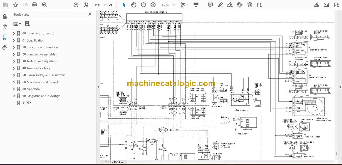
- Electric circuit diagram
- Symbols in electric circuit diagram
- Electrical circuit diagram
- Electrical circuit diagram of air conditioner unit
- INDEX
Komatsu


