The Komatsu GD825A-2 Motor Grader is a heavy production grader used for road building, mine sites, and big earthmoving jobs where blade accuracy and uptime really matter. People who reach for the Komatsu GD825A-2 Motor Grader Shop Manual (SEBMW010715) are usually shop mechanics, field techs, or owners trying to keep an older machine earning instead of parked. They’re typically chasing electrical faults, chasing leaks, or planning major repairs so they don’t have to call in the dealer for every issue.
What this manual helps you do
- Trace hydraulic, steering, and brake problems using factory-style diagnostic steps and system layouts.
- Check and adjust linkages, blade controls, and driveline components so the grader cuts clean and tracks straight.
- Follow engine, transmission, and axle disassembly/assembly sequences so you don’t guess on teardown or re-fit.
- Diagnose electrical issues with wiring information and test-point guidance that most generic books don’t give you.
- Handle scheduled workshop service jobs with the kind of procedures and specs a dealer shop would rely on.
The Shop Manual for Komatsu GD825A-2 Motor Grader walks through diagnostic procedures, disassembly sequences, and reference data used during workshop-level repairs. The Komatsu GD825A-2 Motor Grader Shop Manual (SEBMW010715) usually covers engine, powertrain, hydraulics, steering, brakes, frame, and electrical systems in a format aimed at service technicians.
Who this is for
This is aimed at field techs, independent shop mechanics, and fleet maintenance managers doing real repairs, not just daily checks. If you only need basic operation, safety, and fluid check info, you’re better off with the Operation & Maintenance manual instead.
FAQ
Q: Is this a PDF I can download and search?
A: Yes, it’s typically supplied as a downloadable PDF that you can search on-screen and print selected pages for the shop.
Q: Will this help me rebuild major components, or is it just light service?
A: This kind of shop manual is written for full workshop repairs, from troubleshooting through major component overhaul.
Q: How do I know if it matches my exact GD825A-2 machine?
A: Check your machine’s model and any serial range notes from your seller against the SEBMW010715 reference to confirm it lines up.
Bottom line: If you’re repairing or overhauling a Komatsu GD825A-2 in a workshop or field-service setting, this is the right manual; if you just operate the grader and do daily checks, you should keep looking for the operator/O&M book instead.
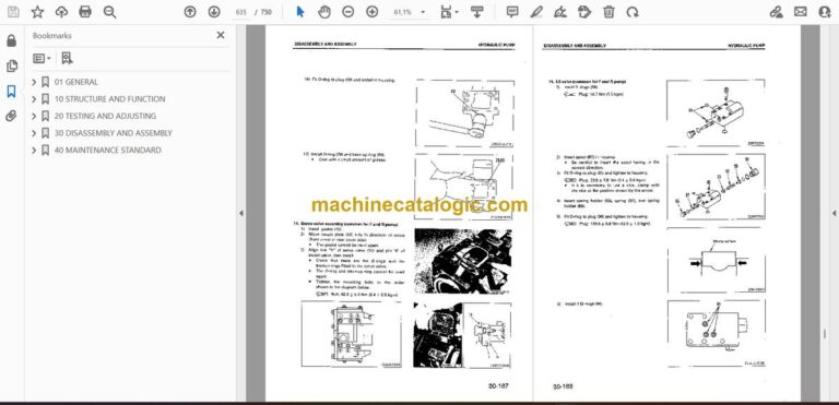
📘 Show Index
Table of Contents:
- 01 GENERAL
- Specification dimension drawings
- Specifications
- Weight table
- Fuel, coolant and lubricants
- 10 STRUCTURE AND FUNCTION
- General
- Power train diagram
- Joint
- HYDROSHIFT transmission and transfer Piping
- Hydraulic circuit for power train
- Hydraulic circuit diagram for power train
- Transmission filter relief valve
- PTO (Power Take Off)
- HYDROSHIFT transmission and transfer
- Transmission control valve
- Transmission control
- Inching control
- Drive shaft
- Final drive, differential lock and unlock piping
- Final drive
- Tandem drive
- Steering piping
- Steering circuit system
- Steering circuit diagram
- Steering valve
- Double relief valve
- Check valve
- Emergency steering system
- Front axle
- Wheel
- Air piping
- Air circuit diagram
- Alcohol injector
- Disc brake
- Parking brake
- Brake air piping
- Brake air circuit system
- Brake air circuit diagram
- Air drier
- Air governor
- Air tank
- Automatic drain valve
- Check valve
- Brake valve
- Parking brake system
- Parking brake solenoid valve
- Exhaust valve
- Spring cylinder
- Hydraulic control piping
- Hydraulic circuit system
- Hydraulic circuit diagram
- Closed center load sensing system (CLSS)
- Hydraulic pump
- Priority divider valve
- Surge pressure absorbing valve
- Hydraulic control valve
- Pressure compensating mechanism of hydraulic control valve
- Blade lift speed adjustment Mechanism
- Pilot check valve
- Pilot check valve (with safety valve)
- Circle rotation motor
- Blade accumulator system
- Blade float system
- Drawbar and lifter
- Blade
- Lifter bracket control piping
- Circle rotation gear
- Rear mount ripper
- Hydraulic control linkage
- Main frame
- Air conditioner
- Electrical wiring diagram
- Monitor panel, cluster gauge and pilot lamp
- Electrical circuit diagram
- Electrical vehicle monitoring system (EVMS)
- Transmission control system
- Sensors
- Engine starting circuit
- Engine stopping circuit
- 20 TESTING AND ADJUSTING
- Standard value table for engine
- Standard value table for testing and adjusting, failure judgment of chassis
- Precautions before work
- Tool list for testing and adjusting
- Testing and adjusting valve clearance
- Measuring compression pressure
- Testing and adjusting fuel injection timing
- Measuring blow-by pressure
- Measuring engine oil pressure
- Measuring exhaust gas color
- Measuring exhaust gas temperature
- Measuring intake air pressure (boost pressure)
- Testing and adjusting fan belt tension
- Testing and adjusting alternator belt tension
- Procedure for adjusting the engine stop motor cable
- Adjusting accelerator control
- Inching pedal travel and operating force
- Measuring transmission oil pressure
- Checking differential locking device oil pressure
- Steering system
- Checking tire runout
- Checking toe-in
- Installation of articulate center pins
- Checking wear of disc
- Checking work equipment control lever travel and operating force
- Checking work equipment hydraulic pressure
- Adjusting work equipment hydraulic pressure
- Measuring hydraulic drift
- Charging blade accumulator with gas
- Adjusting blade lift speed
- Adjusting slip load of circle rotation clutch
- Adjusting clearance of F and R switches
- Adjusting shift potentiometer
- Adjusting inching potentiometer
- Transmission controller
- Adjusting speedometer module of machine monitor
- Pm-CLINIC
- TROUBLESHOOTING
- Precautions before work
- Points to remember when troubleshooting
- Sequence of events in troubleshooting
- Points to remember when carrying out maintenance
- Checks before troubleshooting
- Electrical circuit system diagram
- Connector types and mounting locations
- Electrical wiring diagram
- Connection table for connector pin numbers
- Method of using troubleshooting charts
- TROUBLESHOOTING OF ENGINE (S MODE)
- S-1 Starting performance is poor (Starting always takes time)
- S-2 Engine does not start
- (1) Engine does not turn
- (2) Engine turns but no exhaust gas comes out (Fuel is not being injected)
- (3) Exhaust gas comes out but engine does not start (Fuel is being injected)
- S-3 Engine does not pick up smoothly (Follow-up is poor)
- S-4 Engine stops during operations
- S-5 Engine does not rotate smoothly (hunting)
- S-6 Engine lacks output (no power)
- S-7 Exhaust gas is black (incomplete combustion)
- S-8 Oil consumption is excessive (or exhaust gas is blue)
- S-9 Oil becomes contaminated quickly
- S-10 Fuel consumption is excessive
- S-11 Oil is in cooling water, or water spurts back, or water level goes down
- S-12 Oil pressure lamp lights up (drop in oil pressure)
- S-13 Oil level rises
- S-14 Water temperature becomes too high (overheating)
- S-15 Abnormal noise is made
- S-16 Vibration is excessive
- TROUBLESHOOTING CHART FOR ELECTRONIC VEHICLE MONITORING SYSTEM (M MODE)
- M-1. When starting switch is turned ON, monitor panel display does not appear
- M-2. When starting switch is turned ON, monitor panel display does not go out
- M-3. When starting switch is turned ON (engine stopped), check items flash
- M-4. Preheating operation is not being used but preheating display lights up
- M-5. When starting switch is turned ON and engine is started, caution items flash (but there is no abnormality with engine or CHECK items)
- M-6. Buzzer does not sound for 1 minute when starting switch is turned ON (engine stopped)
- M-7. There is no abnormality displayed on monitor, but buzzer sounds
- M-8. Monitor panel lighting does not light up
- M-9. Service meter does not move after engine is started / Service meter continues to move when engine is stopped
- M-10. Coolant temperature gauge displays abnormally low temperature
- M-11. Coolant temperature gauge does not give a display
- M-12. Fuel level gauge always displays FULL
- M-13. Fuel gauge does not give any display
- M-14. Speedometer display does not work normally
- M-15. Turn signal indicator pilot lamp does not light up
- M-16. High beam pilot lamp does not light up
- TROUBLESHOOTING CHART FOR ELECTRONIC (ENGINE, PARKING BRAKE, TRANSMISSION CONTROL) (E MODE)
- E-1 Engine does not start (starting motor works)
- E-2 Starting motor does not turn
- E-3 Parking brake does not work
- E-4 Parking brake cannot be released
- E-5 Transmission does not shift when transmission lever is moved to a position between F1 and F8, or R1 and R8
- TROUBLESHOOTING OF TRANSMISSION CONTROLLER SYSTEM (ET MODE)
- LED display for transmission controller
- ET-1 [A1] (Short circuit in 1st solenoid) is displayed
- ET-2 [A2] (Short circuit in 2nd solenoid) is displayed
- ET-3 [A3] (Short circuit in 3rd solenoid) is displayed
- ET-4 [A4] (short circuit in 4th solenoid) is displayed
- ET-5 [A5] (Short circuit in High/Low solenoid) is displayed
- ET-6 [A7] (Short circuit in FORWARD/REVERSE solenoid) is displayed
- ET-7 [b1] (Disconnection in 1st solenoid) is displayed
- ET-8 [b2] (Disconnection in 2nd solenoid) is displayed
- ET-9 [b3] (Disconnection in 3rd solenoid) is displayed
- ET-10 [b4] (Disconnection in 4th solenoid) is displayed
- ET-11 [b5] (Disconnection in Low solenoid) is displayed
- ET-12 [b6] (Disconnection in High solenoid) is displayed
- ET-13 [b7] (Disconnection in FORWARD solenoid) is displayed
- ET-14 [b8] (Disconnection in REVERSE solenoid) is displayed
- ET-15 [c1] (Disconnection in inching potentiometer) is displayed
- ET-18 [d1] (Failure in F and R switches) is displayed
- ET-19 [d4] (Disconnection in engine speed sensor) is displayed
- ET-20 [d5] (Disconnection in speed sensor) is displayed
- ET-21 [d6] (Failure in transmission oil temperature sensor) is displayed
- ET-22 [E0] (Drop in power source voltage) is displayed
- ET-23 [E1] (Short circuit in parking brake) is displayed
- ET-24 [E2] or [F2] (Short circuit, disconnection in parking brake lamp) is displayed
- ET-25 [E3] or [F3] (Short circuit, disconnection in differential lock relay) is displayed
- ET-26 [E4] or [F4] (Short circuit, disconnection in backup buzzer relay) is displayed
- ET-27 [E5] or [F5] (Short circuit, disconnection in caution lamp) is displayed
- ET-28 [E6] or [F6] (Short circuit, disconnection in alarm buzzer relay) is displayed
- ET-29 [E7] or [F7] (Short circuit, disconnection in starting motor relay) is displayed
- ET-30 [F1] (Disconnection in parking brake) is displayed
- TROUBLESHOOTING CHART FOR HYDRAULIC SYSTEM (H MODE)
- STANDARDS FOR MEASURING HYDRAULIC PRESSURE, AND JUDGEMENT VALUES
- TABLE OF FAILURE MODES AND CAUSES
- HYDRAULIC PRESSURE MEASUREMENT AND FILTER MOUNTING POSITIONS
- H-1 Abnormal noise is made (from around pump)
- H-2 Relief sound is heard (when not operating)
- H-3 Hydraulic oil overheats (when not operating)
- H-4 Work equipment does not move when control lever is operated (steering at neutral)
- H-5 Work equipment is slow, lacks power
- H-6 There is excessive hydraulic drift of work equipment
- H-7 Steering wheel does not turn (work equipment at neutral)
- H-8 Turning speed is slow, lacks power (work equipment at neutral)
- H-9 Feeling when operating steering wheel is strange
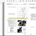
- 30 DISASSEMBLY AND ASSEMBLY
- PRECAUTIONS BEFORE WORK
- COATING MATERIALS LIST
- SPECIAL TOOL LIST
- STARTING MOTOR
- ALTERNATOR
- NOZZLE HOLDER
- FUEL INJECTION PUMP
- WATER PUMP
- ENGINE OIL COOLER CORE
- TURBOCHARGER
- AIR COMPRESSOR
- CYLINDER HEAD
- ENGINE (INCL. TRANSMISSION)
- RADIATOR
- FUEL TANK
- PTO
- TRANSMISSION
- Removal
- Installation
- Disassembly
- Assembly
- TRANSFER
- TRANSMISSION CONTROL VALVE
- HYDROSHIFT TRANSMISSION PUMP
- TANDEM AND FINAL DRIVE
- FINAL DRIVE
- BEVEL GEAR
- BEVEL PINION
- FRONT AXLE
- Removal
- Installation
- Disassembly
- Assembly
- STEERING VALVE
- WHEEL BRAKE
- Removal
- Installation
- Disassembly
- Assembly
- PARKING BRAKE CALIPER PADS
- AIR TANK
- ALCHOL INJECTOR
- HYDRAULIC TANK
- HYDRAULIC PUMP
- Removal
- Installation
- Disassembly
- Assembly
- HYDRAULIC CONTROL VALVE
- MAIN CONTROL VALVE
- CIRCLE ROTATION MOTOR
- DRAWBAR SHIFT CYLINDER, BLADE
- LIFT CYLINDER, LIFTER GUIDE
- ARTICULATE CYLINDER
- REAR MOUNT RIPPER CYLINDER
- HYDRAULIC CYLINDER
- CIRCLE ROTATION GEAR AND HYDRAULIC OIL MOTOR
- Removal
- Installation
- Disassembly
- Assembly
- BLADE
- CIRCLE AND DRAWBAR
- Removal and Installation
- Disassembly
- Assembly
- REAR MOUNT RIPPER
- METHOD FOR LIFTING UP ROPS CAB
- INSTALLATION OF ROPS
- ROPS CAB
- ARTICULATE SECTION
- FLOOR FRAME
- 40 MAINTENANCE STANDARD
- HYDROSHIFT transmission and transfer
- Transmission pump
- Transmission control valve
- Transmission solenoid valve
- Final drive
- Differential lock-up pump
- Tandem drive
- Front axle
- Steering cylinder
- Disc brake
- Parking brake
- Spring cylinder
- Hydraulic control valve
- Hydraulic cylinder
- Hydraulic pump
- Drawbar and lifter
- Blade
- Circle rotation gear
- Ripper
- Frame
Komatsu
