The Komatsu BR380JG-3 Mobile Crusher is a tracked unit you park at the face, feed with an excavator, and use to turn blasted rock or demo debris into usable product on the spot. The Komatsu BR380JG-3 Mobile Crusher Shop Manual (SEN06703-13) is what the dealer techs and serious independent shops reach for when the machine is down and parts are already on the ground. People usually want this when basic troubleshooting isn’t cutting it and they need the proper disassembly order, test points, and adjustment procedures to get it back crushing without guesswork.
What this manual helps you do
- Trace hydraulic faults in the crusher, travel, and conveyor circuits using the normal test gear most field techs carry.
- Diagnose engine, control, and sensor issues by following step-by-step checks for the electronic and monitoring systems.
- Follow correct disassembly and reassembly sequences for the crusher unit, undercarriage, and major structural components.
- Check adjustment procedures for tracks, crusher clearances, and belt systems so the machine runs safely and efficiently after repair.
- Handle scheduled workshop-level overhauls with the right inspection points, wear limits, and reassembly guidelines in one place.
Who this is for
This shop manual is aimed at field technicians, shop mechanics, and fleet maintenance leads who already have basic tooling and some Komatsu experience. If you’re just learning how to operate the crusher or only need daily/weekly service info, you’re better off with the Operation & Maintenance manual instead.
FAQ
Q: Is this a searchable PDF I can download and print?
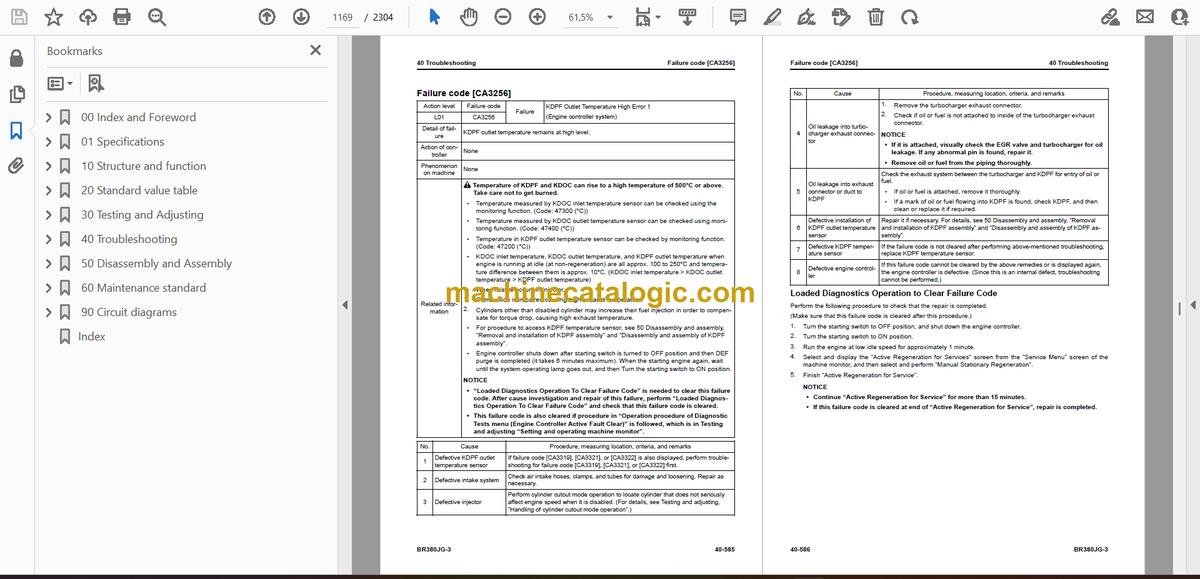
A: Yes, it’s a digital PDF you can download, search by keyword, and print specific sections for use in the field.
Q: Does this go deep enough for full component tear-downs?
A: Yes, the Komatsu BR380JG-3 Mobile Crusher Shop Manual walks through diagnostic procedures, disassembly sequences, and workshop-level reassembly steps used during major repairs.
Q: How do I know if it matches my exact BR380JG-3?
A: Check your machine’s identification plate and confirm it’s a BR380JG-3; if your serial tag shows a different model or variant, you may need a different book reference than SEN06703-13.
If you’re the one who actually has to fix a BR380JG-3 and sign off on it, this is the right manual; if you just run the machine or handle parts orders, you should keep looking for a different document type.
📘 Show Index
Table of Contents:
- 00 Index and Foreword
- Index
- Abbreviation List
- Foreword, Safety, Basic Information
- How to Read the Shop Manual
- Safety Notice for Operation
- Precautions to Prevent Fire
- Procedures If Fire Occurs
- Precautions when disposing of waste materials
- Exhaust gas regulations – Actions taken
- Precautions for DEF
- General Character and Precautions for Handling
- Precautions for Adding
- Precautions for Storage
- Precautions for Fire Hazard and Leakage
- Other Precautions
- Store DEF
- Precautions When You Handle Hydraulic Equipment
- Precautions When You Disconnect and Connect Pipings
- Precautions When You Handle Electrical Equipment
- Precautions When You Handle Fuel System Equipment
- Precautions When You Handle Intake System Equipment
- Practical Use of KOMTRAX
- Disconnect and Connect Push-Pull Type Coupler
- How to Disconnect and Connect Type 1 Push-Pull Type Coupler
- How to Disconnect and Connect Type 2 Push-Pull Type Coupler
- How to Disconnect and Connect Type 3 Push-Pull Type Coupler
- Precautions for Disconnection and Connection of Connectors
- How to Disconnect and Connect Deutsch Connector
- How to Disconnect and Connect Slide Lock Type Connector
- How to Disconnect and Connect Connector with Lock to Pull
- How to Disconnect and Connect Connector with Lock to Push
- How to Disconnect and Connect Connector with Housing to Rotate
- How to Read the Codes for Electric Cable
- Explanation of Terms for Maintenance Standard
- Standard Tightening Torque Table
- Conversion Table
- 01 Specifications
- Table of Contents
- Specifications
- Specification Drawing
- Specification drawing of BR380JG-3
- Specifications
- Specifications of BR380JG-3
- Weight Table
- How to Use Fuel, Coolant and Lubricants by Ambient Temperature
- 10 Structure and function
- Contents
- Urea SCR system
- Urea SCR system component layout drawing
- Urea SCR system diagram
- Urea SCR system functions
- Function of DEF system
- Inducement Strategy
- Urea SCR system components
- DEF mixing tube
- SCR assembly
- DEF tank
- DEF tank sensor
- DEF pump
- DEF injector
- DEF hose
- DEF tank heating valve
- Starting system
- Starting system component layout drawing
- System operating lamp system
- System operating lamp system diagram
- Function of system operating lamp system
- Battery disconnect switch
- Function of battery disconnect switch
- Engine system
- Engine system component layout drawing
- Specification of engine system
- Function of engine system
- Engine control system
- Engine control system diagram
- Function of engine control system
- Engine automatic warm-up system
- Engine automatic warm-up system diagram
- Function of engine automatic warm-up system diagram
- Overheat prevention system
- Overheat prevention system diagram
- Function of overheat prevention system
- Turbocharger protection system
- Turbocharger protection system diagram
- Function of turbocharger protection system
- Engine system component
- VGT
- EGR system
- EGR valve
- EGR cooler
- KCCV system
- KCCV ventilator
- CDR Valve
- KDPF
- Cooling system
- Cooling system component layout drawing
- Specification of cooling system
- Control system
- Control system component layout drawing
- Machine monitor system
- Machine monitor system diagram
- KOMTRAX system
- KOMTRAX system diagram
- Function of KOMTRAX system
- Control system component
- Machine monitor
- Gateway function controller
- Communication terminal
- Work equipment controller
- CAN terminating resistor
- Engine controller
- Fuel control dial
- Hydraulic system
- Hydraulic system component layout drawing
- CLSS
- Structure of CLSS
- Pump swash plate angle (flow rate) control
- Pressure compensation control
- Pump and engine combined control system
- Pump and engine combined control system diagram
- Function of pump and engine combined control system
- Control function when emergency travel operation switch is set to ON
- Pump and valve control system
- Pump and valve control system diagram
- Function of pump and valve control system
- Hydraulic system components
- Hydraulic tank
- Oil filler cap of hydraulic tank
- Breather of hydraulic tank
- Main pump
- Control valve
- Work equipment system
- Work equipment system component layout drawing
- Structure of valve control
- Grizzly feeder semi automatic control system
- Structure of grizzly feeder semi automatic control system
- Function of grizzly feeder semi automatic control system
- Abnormal load shutdown system
- Function of abnormal load shutdown system
- Crusher jaw tip adjustment system
- Crusher jaw tip adjustment system diagram
- Function of crusher jaw tip adjustment system
- Work equipment system components
- Crusher motor
- Crusher motor
- Grizzly feeder motor
- Conveyor motor
- Solenoid valve
- EPC valve
- Electromagnet selector valve for lock cylinder
- Electromagnet selector valve for conveyor lift cylinder
- Electromagnet selector valve for conveyor motor
- Travel system
- Travel system component layout drawing
- Travel control system diagram
- Function of travel control system
- Travel system components
- Undercarriage and frame
- Undercarriage layout drawing
- Specification of undercarriage
- Work equipment
- Primary conveyor
- Structure of primary conveyor
- Grizzly feeder
- Structure of grizzly feeder
- Crusher
- Vibrator
- 20 Standard value table
- Contents
- Standard value table for engine
- Standard value table for engine: BR380JG-3
- Standard value table for machine
- Standard value table for machine: BR380JG-3
- Machine posture and measuring procedure drawings for performance measurement
- 30 Testing and Adjusting
- Table of Contents
- Precautions Before Work
- Related Information on Testing and Adjusting
- Differences In Machine Monitor Symbols
- Tools for testing and adjusting
- Sketches for testing and adjusting tools
- Engine and Cooling System
- Testing engine speed
- Procedure for testing engine speed
- Testing engine speed at high idle
- Testing engine speed at low idle
- Testing engine speed with 2 pumps at hydraulic relief
- Testing boost pressure
- Procedure for testing boost pressure using machine monitor
- Procedure for testing boost pressure using testing tools
- Testing exhaust gas color
- Procedure for testing exhaust gas color using handy smoke checker
- Procedure for testing exhaust gas color using smoke meter
- Examine Mass Air Flow and Temperature Sensor
- How to Examine Mass Air Flow and Temperature Sensor
- Testing and adjusting valve clearance
- Procedure for testing valve clearance
- Procedure for adjusting valve clearance
- Testing compression pressure
- Procedure for testing compression pressure
- Testing blowby pressure
- Procedure for testing blowby pressure
- Testing engine oil pressure
- Procedure for testing engine oil pressure
- Testing EGR valve and VGT oil pressures
- Procedure for testing EGR valve and VGT oil pressures
- Testing fuel pressure
- Procedure for testing fuel pressure
- Testing fuel discharged volume, return rate, and leakage
- Procedure for testing fuel discharged volume, return rate, and leakage
- Bleeding air from fuel system
- Procedure for bleeding air from fuel system
- Testing leakage from fuel system
- Procedure for testing leakage from fuel system
- Handling cylinder cutout mode operation
- Handling no-injection cranking operation
- Test fan belt and alternator belt
- Test fan belt and alternator belt
- Test automatic tensioner
- Correct Soot Accumulation Correction Value by Ash Influence
- Procedure for writing soot correction by ash influence to engine controller
- Testing SCR-related functions
- Testing DEF pump pressure boost
- Testing injection quantity of DEF injector
- Testing DEF line heater relay 1
- Testing DEF line heater relay 2
- Testing DEF pump heater relay
- Testing DEF tank heater relay
- Testing SCR denitration efficiency
- Flushing DEF tank
- Procedure for flushing DEF tank
- Clean DEF pump
- Method for clean DEF pump
- Undercarriage and Frame
- Testing and adjusting track shoe tension
- Procedure for testing track shoe tension
- Procedure for adjusting track shoe tension
- Hydraulic System
- Releasing remaining pressure from hydraulic system
- Procedure for releasing remaining pressure from hydraulic tank
- Procedure for releasing remaining pressure from travel motor circuit
- Testing and adjusting oil pressure in work equipment and travel circuits
- Procedure for testing and adjusting oil pressure in work equipment and travel circuits
- Procedure for adjusting oil pressure in work equipment and travel circuits
- Testing control circuit pressure
- Procedure for testing control circuit pressure
- Testing and adjusting pump PC control circuit pressure
- Procedure for testing PC valve outlet pressure (servo piston inlet pressure)
- Procedure for testing PC-EPC valve outlet pressure
- Procedure for adjusting pump PC control circuit pressure
- Testing and adjusting pump LS control circuit pressure
- Procedure for testing LS differential pressure using machine monitor
- Procedure for testing LS differential pressure using testing tools
- Procedure for testing LS valve outlet pressure (servo piston inlet pressure)
- Procedure for testing LS-EPC valve outlet pressure
- Procedure for adjusting LS valve
- Testing solenoid valve output pressure
- Procedure for testing solenoid valve outlet pressure
- Solenoid valve operating condition
- Testing PPC valve outlet pressure
- Procedure for testing PPC valve outlet pressure
- Testing oil leakage
- Procedure for testing oil leakage from travel motor
- Bleeding air from hydraulic circuit
- Procedure for bleeding air from hydraulic system
- Procedure for adjusting mirrors
- Electrical System
- Setting and operating machine monitor
- About operator mode
- Display function of the technician identification status screen
- Display function of the operator identification input screen
- Function of checking LCD (Liquid Crystal Display) display
- Function of checking service meter
- Function of setting usage limitation and changing maintenance password
- About Service Mode
- Operation procedure of Service Mode
- Procedure for checking Pre-defined Monitoring data
- Procedure for checking monitoring data
- About abnormality record
- Procedure for checking Maintenance Record
- Operation procedure of Maintenance Mode Setting
- Operation procedure of Phone Number Entry
- About Default menu
- About Diagnostic Test menu
- About Adjustment menu
- Operation procedure of No-Injection Cranking
- Procedure for checking Crusher Clearance History
- Procedure for checking Lock Cylinder Slide History
- About KOMTRAX Settings
- Procedure for displaying Service Message
- How to Start Up KOMTRAX System (Machine with Gateway Function Controller)
- How to Stop Use of KOMTRAX System (Machine with Gateway Function Controller)
- Handling voltage circuit of engine controller
- Handling battery disconnect switch
- Testing diode
- Procedure for testing diode using digital multimeter
- Procedure for testing diode using analog multimeter
- Pm Clinic
- Pm Clinic Service
- Pm Clinic Check Sheet: BR380JG-3
- 40 Troubleshooting
- Table of Contents
- Precautions Before Work
- Related Information to Troubleshooting
- General Troubleshooting Points
- Troubleshooting Points for Urea SCR System
- Sequence of Events in Troubleshooting
- Check before starting troubleshooting
- Examine Water Pump for Leakage
- Procedure for checking electrical parts
- Procedure for Troubleshooting
- Symptom of failure and troubleshooting numbers
- Information Shown in Troubleshooting Table
- How to Diagnose Wiring Harness for Open Circuit of Pressure Sensor System
- Connector List and Layout (Part Number of Work Equipment Controller: In the 7838-51-1000s)
- Connector List and Layout (Part Number of Work Equipment Controller: In the 7838-52-1000s)
- Connector Contact Connection Table
- T-Branch Box and T-Branch Adapter Table
- Fuse location table
- Precautions When You Clean and Replace KDPF (KCSF and KDOC)
- Prepare of Short Socket Adapter (For Failure Codes [CA1883], [CB1883], [CA3135] and [CB3135])
- Failure codes table
- Troubleshooting by Failure Code (Display of Code)
- Failure code [7RC1KB]
- Failure code [7RC2KA]
- Failure code [7RC5KB]
- Failure code [7RD2KA]
- Failure code [7RD2KB]
- Failure code [7RD2KY]
- Failure code [7RE1KB]
- Failure code [7RE2KA]
- Failure code [7RE6KB]
- Failure code [7RE7KA]
- Failure code [7RE8KB]
- Failure code [7RE9KA]
- Failure code [7REAKB]
- Failure code [7REDMA]
- Failure code [7REEMA]
- Failure code [7RENKZ]
- Failure code [7REPKA]
- Failure code [7RESKB]
- Failure code [7RETKA]
- Failure code [7RF2KA]
- Failure code [7RF2KB]
- Failure code [7RF2KY]
- Failure code [7RF3KA]
- Failure code [7RF3KB]
- Failure code [7RF3KY]
- Failure code [7RF4KA]
- Failure code [7RF4KB]
- Failure code [7RF4KY]
- Failure code [7RFAKA]
- Failure code [7RFAKB]
- Failure code [7RFAKY]
- Failure code [7RFBKA]
- Failure code [7RFBKB]
- Failure code [7RFBKY]
- Failure code [7RFHKA]
- Failure code [7RFHKB]
- Failure code [7RFHKY]
- Failure code [7RFKKA]
- Failure code [7RFKKB]
- Failure code [7RFKKY]
- Failure code [7RFLKA]
- Failure code [7RFLKB]
- Failure code [7RFLKY]
- Failure code [7RFMKA]
- Failure code [7RFMKB]
- Failure code [7RFMKY]
- Failure code [7RFNKA]
- Failure code [7RFNKB]
- Failure code [7RFNKY]
- Failure code [7RFPKA]
- Failure code [7RFPKB]
- Failure code [7RFPKY]
- Failure code [7RGAMA]
- Failure code [7RJAKA]
- Failure code [7RJAKB]
- Failure code [7RJAKY]
- Failure code [7RJLKA]
- Failure code [7RJLKB]
- Failure code [7RJLKY]
- Failure code [7RJMMW]
- Failure code [7RJNMA]
- Failure code [7RJPKB]
- Failure code [7RJQKB]
- Failure code [7RJRKB]
- Failure code [7RJSMA]
- Failure code [989L00]
- Failure code [989M00]
- Failure code [989N00]
- Failure code [A1U0N3]
- Failure code [A1U0N4]
- Failure code [AA10NX]
- Failure code [AB00KE]
- Failure code [AQ10N3]
- Failure code [AS00N3]
- Failure code [AS00R2]
- Failure code [AS00R3]
- Failure code [AS00R4]
- Failure code [AS00R5]
- Failure code [AS00R6]
- Failure code [AS00ZK]
- Failure code [AS10KM]
- Failure code [AS10NR]
- Failure code [AS10NT]
- Failure code [B@BAZG]
- Failure code [B@BAZK]
- Failure code [B@BCNS]
- Failure code [B@BCQA]
- Failure code [B@BCZK]
- Failure code [B@HANS]
- Failure code [CA115]
- Failure code [CA122]
- Failure code [CA123]
- Failure code [CA131]
- Failure code [CA132]
- Failure code [CA144]
- Failure code [CA145]
- Failure code [CA153]
- Failure code [CA154]
- Failure code [CA187]
- Failure code [CA221]
- Failure code [CA222]
- Failure code [CA227]
- Failure code [CA234]
- Failure code [CA238]
- Failure code [CA239]
- Failure code [CA249]
- Failure code [CA256]
- Failure code [CA271]
- Failure code [CA272]
- Failure code [CA322]
- Failure code [CA323]
- Failure code [CA324]
- Failure code [CA325]
- Failure code [CA331]
- Failure code [CA332]
- Failure code [CA343]
- Failure code [CA351]
- Failure code [CA352]
- Failure code [CA356]
- Failure code [CA357]
- Failure code [CA386]
- Failure code [CA428]
- Failure code [CA429]
- Failure code [CA435]
- Failure code [CA441]
- Failure code [CA442]
- Failure code [CA449]
- Failure code [CA451]
- Failure code [CA452]
- Failure code [CA488]
- Failure code [CA515]
- Failure code [CA516]
- Failure code [CA553]
- Failure code [CA555]
- Failure code [CA556]
- Failure code [CA559]
- Failure code [CA595]
- Failure Code [CA687]
- Failure code [CA689]
- Failure code [CA691]
- Failure code [CA692]
- Failure code [CA697]
- Failure code [CA698]
- Failure code [CA731]
- Failure code [CA778]
- Failure code [CA1117]
- Failure code [CA1664]
- Failure code [CA1669]
- Failure code [CA1673]
- Failure code [CA1677]
- Failure code [CA1678]
- Failure code [CA1682]
- Failure code [CA1683]
- Failure code [CA1684]
- Failure code [CA1686]
- Failure code [CA1691]
- Failure code [CA1694]
- Failure code [CA1695]
- Failure code [CA1696]
- Failure code [CA1712]
- Failure code [CA1713]
- Failure code [CA1714]
- Failure code [CA1715]
- Failure code [CA1776]
- Failure code [CA1777]
- Failure code [CA1843]
- Failure code [CA1844]
- Failure code [CA1879]
- Failure code [CA1881]
- Failure Code [CA1883]
- Failure code [CA1885]
- Failure code [CA1887]
- Failure code [CA1921]
- Failure code [CA1922]
- Failure code [CA1942]
- Failure Code [CA1993]
- Failure code [CA2185]
- Failure code [CA2186]
- Failure code [CA2249]
- Failure code [CA2271]
- Failure code [CA2272]
- Failure code [CA2288]
- Failure code [CA2311]
- Failure code [CA2349]
- Failure code [CA2353]
- Failure code [CA2357]
- Failure code [CA2381]
- Failure code [CA2382]
- Failure code [CA2383]
- Failure code [CA2386]
- Failure code [CA2387]
- Failure code [CA2555]
- Failure code [CA2556]
- Failure code [CA2637]
- Failure code [CA2639]
- Failure code [CA2771]
- Failure code [CA2777]
- Failure code [CA2976]
- Failure code [CA3133]
- Failure code [CA3134]
- Failure code [CA3135]
- Failure code [CA3142]
- Failure code [CA3143]
- Failure code [CA3144]
- Failure code [CA3146]
- Failure code [CA3147]
- Failure code [CA3148]
- Failure code [CA3151]
- Failure code [CA3165]
- Failure code [CA3229]
- Failure code [CA3231]
- Failure code [CA3232]
- Failure code [CA3235]
- Failure code [CA3239]
- Failure code [CA3241]
- Failure code [CA3242]
- Failure code [CA3251]
- Failure code [CA3253]
- Failure code [CA3254]
- Failure code [CA3255]
- Failure code [CA3256]
- Failure code [CA3311]
- Failure code [CA3312]
- Failure code [CA3313]
- Failure code [CA3314]
- Failure code [CA3315]
- Failure code [CA3316]
- Failure code [CA3317]
- Failure code [CA3318]
- Failure code [CA3319]
- Failure code [CA3321]
- Failure code [CA3322]
- Failure code [CA3419]
- Failure code [CA3421]
- Failure code [CA3497]
- Failure code [CA3498]
- Failure code [CA3543]
- Failure code [CA3545]
- Failure code [CA3547]
- Failure code [CA3558]
- Failure code [CA3559]
- Failure code [CA3562]
- Failure code [CA3563]
- Failure code [CA3567]
- Failure code [CA3568]
- Failure code [CA3571]
- Failure code [CA3572]
- Failure code [CA3574]
- Failure code [CA3575]
- Failure code [CA3577]
- Failure code [CA3578]
- Failure code [CA3582]
- Failure code [CA3583]
- Failure code [CA3596]
- Failure code [CA3649]
- Failure code [CA3681]
- Failure code [CA3682]
- Failure code [CA3713]
- Failure code [CA3717]
- Failure code [CA3718]
- Failure code [CA3725]
- Failure code [CA3741]
- Failure code [CA3748]
- Failure code [CA3751]
- Failure code [CA3755]
- Failure code [CA3866]
- Failure code [CA3867]
- Failure code [CA3868]
- Failure code [CA3899]
- Failure code [CA3911]
- Failure code [CA3912]
- Failure code [CA3932]
- Failure code [CA3933]
- Failure code [CA3934]
- Failure code [CA3935]
- Failure code [CA3936]
- Failure code [CA4151]
- Failure code [CA4152]
- Failure code [CA4155]
- Failure code [CA4156]
- Failure code [CA4157]
- Failure code [CA4158]
- Failure code [CA4159]
- Failure code [CA4161]
- Failure code [CA4162]
- Failure code [CA4163]
- Failure code [CA4164]
- Failure code [CA4165]
- Failure code [CA4166]
- Failure code [CA4168]
- Failure code [CA4169]
- Failure code [CA4171]
- Failure code [CA4249]
- Failure code [CA4251]
- Failure code [CA4259]
- Failure code [CA4261]
- Failure code [CA4277]
- Failure code [CA4281]
- Failure code [CA4459]
- Failure code [CA4461]
- Failure code [CA4658]
- Failure code [CA4731]
- Failure code [CA4732]
- Failure code [CA4739]
- Failure code [CA4768]
- Failure code [CA4769]
- Failure code [CA4842]
- Failure code [CA4952]
- Failure code [CA5115]
- Failure code [CA5179]
- Failure code [CA5181]
- Failure code [CA5383]
- Failure code [D110KB]
- Failure code [D162KY]
- Failure code [D162KZ]
- Failure code [D19JKZ]
- Failure code [D811MC]
- Failure code [D862KA]
- Failure code [D8ALKA]
- Failure code [D8ALKB]
- Failure code [D8AQKR]
- Failure code [D8ARKR]
- Failure code [D8G1KT]
- Failure code [D8G6KT]
- Failure code [DA22KK]
- Failure code [DA25KP]
- Failure code [DA26KP]
- Failure code [DA29KQ]
- Failure code [DA2LKA]
- Failure code [DA2LKB]
- Failure code [DAF0MB]
- Failure code [DAF0MC]
- Failure code [DAF7KB]
- Failure code [DAF9KQ]
- Failure code [DAFGMC]
- Failure code [DAFLKA]
- Failure code [DAFLKB]
- Failure code [DAFQKR]
- Failure code [DAFSMC]
- Failure code [DB2QKR]
- Failure code [DB2RKR]
- Failure code [DB90MC]
- Failure code [DB9QKR]
- Failure code [DB9RKR]
- Failure code [DDA6KA] (Part Number of Work Equipment Controller: In the 7838-51-1000s)
- Failure code [DGH2KA]
- Failure code [DGH2KB]
- Failure code [DHA4KA]
- Failure code [DHAAMA]
- Failure code [DHACMA]
- Failure code [DHPAMA]
- Failure code [DHPBMA]
- Failure code [DUB0KY]
- Failure code [DUB0KZ]
- Failure code [DXA8KA]
- Failure code [DXA8KB]
- Failure code [DXA9KA]
- Failure code [DXA9KB]
- Failure code [DXE0KA]
- Failure code [DXE0KB]
- Failure code [F311KA]
- Failure code [F311KB]
- Failure code [F312KA]
- Failure code [F312KB]
- Failure code [F313KA]
- Failure code [F313KB]
- Failure code [F314KA]
- Failure code [F314KB]
- Failure code [F315KB]
- Failure code [F315KY]
- Failure code [F316KB]
- Failure code [F316KY]
- Failure code [F318KB]
- Failure code [F318KY]
- Failure code [F31AKB]
- Failure code [F31AKY]
- Failure code [F31BKB]
- Failure code [F31BKY]
- Failure code [F31CKB]
- Failure code [F31CKY]
- Failure code [F31DKB]
- Failure code [F31DKY]
- Failure code [F31EKB]
- Failure code [F31EKY]
- Troubleshooting of Electrical System (E-Mode)
- E-1 Engine does not start. (Engine does not crank.) (Part Number of Work Equipment Controller: In the 7838-51-1000s)
- E-1 Engine does not start. (Engine does not crank.) (Part Number of Work Equipment Controller: In the 7838-52-1000s)
- E-2 Manual preheating does not work.
- E-3 Automatic preheating does not work.
- E-4 Preheat monitor does not light up when preheating operation is performed.
- E-5 When starting switch is turned to ON position, machine monitor displays nothing.
- E-6 Engine oil level monitor lights up yellow when starting switch is in ON position but engine is stopped.
- E-7 Radiator coolant level monitor lights up yellow when starting switch is in ON position but engine is stopped.
- E-8 Engine coolant temperature monitor lights up white while engine is running.
- E-9 Hydraulic oil temperature monitor lights up white while engine is running.
- E-10 Air cleaner clogging monitor lights up yellow while engine is running.
- E-11 Charge level monitor lights up red while engine is running.
- E-12 Fuel level monitor lights up red while engine is running.
- E-13 Water separator monitor lights up red while engine is running.
- E-14 Engine coolant temperature monitor lights up red while engine is running.
- E-15 Engine oil pressure monitor lights up red while engine is running.
- E-16 Hydraulic oil temperature monitor lights up red while engine is running.
- E-17 Indicator of fuel gauge remains at the minimum or maximum display position.
- E-18 Indication of fuel gauge does not agree with actual fuel level.
- E-19 Indicator of engine coolant temperature gauge remains at the minimum or maximum display position.
- E-20 Indication of engine coolant temperature gauge does not agree with actual coolant temperature.
- E-21 Hydraulic oil temperature gauge does not move from minimum or maximum.
- E-22 Indication of hydraulic oil temperature gauge does not agree with actual oil temperature.
- E-23 Machine monitor displays nothing partially on screen.
- E-24 Function switch does not work.
- E-25 Automatic warm-up system does not work (in cold weather).
- E-26 Travel speed monitor does not light up or go off when travel speed switch is operated.
- E-27 When travel speed setting is switched, current travel speed does not change
- E-28 Alarm buzzer does not stop sounding.
- E-29 Machine monitor does not display service meter when starting switch is in OFF position.
- E-30 Machine monitor cannot be switched to service mode.
- E-31 All work equipment stop suddenly.
- E-32 Message of "Under emergency stop" is displayed red immediately after engine is started. (Part Number of Work Equipment Controller: In the 7838-51-1000s)
- E-32 Message of "Emergency stop (engine)" is displayed red immediately after engine is started. (Part Number of Work Equipment Controller: In the 7838-52-1000s)
- E-33 Alarm buzzer does not sound while machine is traveling.
- E-34 Alarm buzzer does not stop sounding while machine is not traveling.
- E-35 Horn does not sound.
- E-36 Horn does not stop sounding.
- E-37 Operation mode does not switch between Travel, Work, and Inspection modes.
- E-38 Crusher clearance adjustment mode cannot be switched.
- E-39 Crusher rotation cannot be switched between normal and reverse rotations.
- E-40 Machine cannot travel
- E-41 Machine cannot travel under radio control.
- E-42 Feeder cannot be turned on or off under radio control.
- E-43 One-touch start and stop of work equipment cannot be performed under radio control.
- E-44 Nothing is displayed when monitor switches are operated.
- E-45 Crusher cannot be controlled using crusher manual forward and reverse rotation switches on monitor.
- E-46 Conveyor cannot be controlled using conveyor manual forward and reverse rotation switches on monitor.
- E-47 KOMTRAX system does not operate normally.
- Troubleshooting for Hydraulic and Mechanical Systems (H Mode)
- H-1 All work equipment and travel system move too slow or lack power.
- H-2 Engine speed drops significantly or engine stalls.
- H-3 All work equipment and travel system do not operate.
- H-4 Unusual noise is heard from around hydraulic pump.
- H-5 Fine control performance or response is poor.
- H-6 Conveyor does not operate.
- H-7 Conveyor moves too slow or lacks power.
- H-8 Crusher does not operate.
- H-9 Crusher does not rotate smoothly or lacks power.
- H-10 Feeder does not operate.
- H-11 Feed performance of feeder is poor. (Vibration frequency is small.)
- H-12 Magnetic separator does not operate.
- H-13 Magnetic separator belt moves too slow.
- H-14 Muck discharge conveyor does not operate.
- H-15 Muck discharge conveyor moves too slow or lacks power.
- H-16 Primary conveyor and muck discharge conveyor do not move up and down.
- H-17 Machine deviates during traveling.
- H-18 Travel speed is too slow.
- H-19 Machine is hard to be steered or steering system lacks power.
- H-20 Track does not operate (only either side)
- H-21 Machine cannot travel when travel switch on radio control unit is pressed.
- H-22 Crusher clearance cannot be opened nor closed.
- Troubleshooting of Engine (S-Mode)
- Information described in troubleshooting table (S mode)
- S-1 Engine does not crank when starting switch is turned to "START" position.
- S-2 Engine cranks but no exhaust gas is discharged.
- S-3 Fuel is injected but engine does not start. (Engine cranks but cannot start due to incomplete combustion.)
- S-4 Engine startability is poor.
- S-5 Engine pickup is poor.
- S-6 Running engine stops.
- S-7 Engine rotation is unstable.
- S-8 Engine output is insufficient. (Engine lacks power.)
- S-9 KDPF is clogged early.
- S-10 Engine oil consumption is excessive.
- S-11 Engine oil is contaminated early.
- S-12 Fuel consumption is excessive.
- S-13 Oil gets mixed in coolant. (Or coolant blows back and reduces.)
- S-14 Engine oil pressure drops.
- S-15 Fuel gets mixed in engine oil.
- S-16 Water gets mixed in engine oil. (Engine oil becomes cloudy.)
- S-17 Coolant temperature rises too high. (Coolant overheats.)
- S-18 Unusual noise is heard.
- S-19 Vibrations are too large.
- S-20 Air cannot be bled from fuel circuit.
- S-21 Active regeneration is performed too frequently.
- S-22 Active regeneration duration is too long.
- S-23 White smoke is exhausted during active regeneration.
- S-24 DEF consumption is excessive.
- S-25 There is an unusual smell (irritating odor).
- S-26 Foreign material gets mixed in DEF. (DEF level increases.)
- 50 Disassembly and Assembly
- Contents
- Precautions Before Work
- Related Information on Disassembly and Assembly
- How to Read This Manual
- Coating Materials List
- Special tools list
- Sketches of special tools
- Engine and cooling system
- Removal and installation of supply pump assembly
- Procedure for removing supply pump assembly
- Procedure for installing supply pump assembly
- Removal and installation of injector assembly
- Procedure for removing injector assembly
- Installation method of injector assembly
- Removal and installation of cylinder head assembly
- Procedure for removing cylinder head assembly
- Procedure for installing cylinder head assembly
- Removal and installation of EGR valve assembly
- Procedure for removing EGR valve assembly
- Procedure for installing EGR valve assembly
- Removal and installation of EGR cooler assembly
- Procedure for removing EGR cooler assembly
- Procedure for installing EGR cooler assembly
- Removal and installation of starting motor assembly
- Procedure for removing starting motor assembly
- Procedure for installing starting motor assembly
- Removal and installation of alternator belt
- Procedure for removing alternator belt
- Procedure for installing alternator belt
- Removal and installation of radiator assembly
- Procedure for removing radiator assembly
- Procedure for installing radiator assembly
- Removal and installation of hydraulic oil cooler assembly
- Procedure for removing hydraulic oil cooler assembly
- Procedure for installing hydraulic oil cooler assembly
- Removal and installation of aftercooler assembly
- Procedure for removing aftercooler assembly
- Procedure for installing aftercooler assembly
- Removal and installation of engine and main pump assembly
- Procedure for removing engine and main pump assembly
- Procedure for installing engine and main pump assembly
- Removal and installation of engine front oil seal
- Procedure for removing engine front oil seal
- Procedure for installing engine front oil seal
- Removal and installation of engine rear oil seal
- Procedure for removing engine rear oil seal
- Procedure for installing engine rear oil seal
- Removal and installation of fuel cooler assembly
- Procedure for removing fuel cooler assembly
- Procedure for installing fuel cooler assembly
- Removal and installation of engine hood assembly
- Procedure for removing engine hood assembly
- Procedure for installing engine hood assembly
- Removal and installation of fuel tank assembly
- Procedure for removing fuel tank assembly
- Procedure for installing fuel tank assembly
- Removal and installation of DEF tank assembly
- Procedure for removing DEF tank assembly
- Procedure for installing DEF tank assembly
- Removal and installation of DEF tank sensor flange assembly
- Procedure for removing DEF tank sensor flange assembly
- Procedure for installing DEF tank sensor flange assembly
- Remove and Install DEF Tank Sensor
- How to Remove DEF Tank Sensor
- How to Install DEF Tank Sensor
- Removal and installation of DEF tank strainer
- Procedure for removing DEF tank strainer
- Procedure for installing DEF tank strainer
- Removal and installation of DEF tank filler port filter
- Procedure for removing DEF tank filler port filter
- Procedure for installing DEF tank filler port filter
- Removal and installation of KDPF assembly
- Procedure for removing KDPF assembly
- Procedure for installing KDPF assembly
- Disassembly and assembly of KDPF assembly
- Procedure for disassembling KDPF assembly
- Procedure for assembling KDPF assembly
- Removal and installation of SCR assembly
- Procedure for removing SCR assembly
- Procedure for installing SCR assembly
- Removal and installation of KDPF and SCR assembly
- Procedure for removing KDPF and SCR assembly
- Procedure for installing KDPF and SCR assembly
- Removal and installation of bracket for KDPF and SCR assembly
- Procedure for removing bracket for KDPF and SCR assembly
- Procedure for installing bracket for KDPF and SCR assembly
- Removal and installation of KCCV assembly
- Procedure for removing KCCV assembly
- Procedure for installing KCCV assembly
- Removal and installation of DEF mixing tube
- Procedure for removing DEF mixing tube
- Procedure for installing DEF mixing tube
- Removal and installation of DEF injector
- Procedure for removing DEF injector
- Procedure for installing DEF injector
- Removal and installation of DEF pump assembly
- Procedure for removing DEF pump assembly
- Procedure for installing DEF pump assembly
- Removal and installation of DEF hose
- Procedure for removing DEF hose
- Procedure for installing DEF hose
- Removal and installation of air cleaner assembly
- Procedure for removing air cleaner assembly
- Method for installing air cleaner assembly
- Power train
- Removal and installation of travel motor, final drive assembly
- Procedure for removing travel motor and final drive assembly
- Procedure for installing travel motor and final drive assembly
- Disassembly and assembly of final drive assembly
- Procedure for disassembly of final drive assembly
- Procedure for assembly of final drive assembly
- Undercarriage and frame
- Separation and connection of track shoe assembly
- Procedure for separating track shoe assembly
- Procedure for connecting track shoe assembly
- Removal and installation of sprocket
- Procedure for removing sprocket
- Procedure for installing sprocket
- Removal and installation of idler and idler cushion assembly
- Procedure for removing idler and idler cushion assembly
- Procedure for installing idler and idler cushion assembly
- Disassembly and assembly of idler assembly
- Procedure for disassembling idler assembly
- Procedure for assembling idler assembly
- Disassembly and assembly of idler cushion assembly
- Procedure for disassembling idler cushion assembly
- Procedure for assembling idler cushion assembly
- Disassembly and assembly of track roller assembly
- Procedure for disassembling track roller assembly
- Procedure for assembling track roller assembly
- Disassembly and assembly of carrier roller assembly
- Procedure for disassembling carrier roller assembly
- Procedure for assembling carrier roller assembly
- Hydraulic system
- Removal and installation of hydraulic tank assembly
- Procedure for removing hydraulic tank assembly
- Procedure for installing hydraulic tank assembly
- Removal and installation of main pump assembly
- Procedure for removing main pump assembly
- Procedure for installing main pump assembly
- Removal and installation of control valve assembly
- Procedure for removing control valve assembly
- Procedure for installing control valve assembly
- Removal and installation of crusher motor assembly
- Procedure for removing crusher motor assembly
- Procedure for installing crusher motor assembly
- Removal and installation of lock cylinder assembly
- Procedure for removing lock cylinder assembly
- Procedure for installing lock cylinder assembly
- Disassembly and assembly of lock cylinder assembly
- Procedure for disassembling lock cylinder assembly
- Procedure for assembling lock cylinder assembly
- Removal and installation of primary conveyor motor
- Procedure for removing primary conveyor motor
- Procedure for installing primary conveyor motor
- Removal and installation of grizzly feeder motor assembly
- Procedure for removing grizzly feeder motor assembly
- Procedure for installing grizzly feeder motor assembly
- Removal and installation of magnetic separator motor assembly
- Procedure for removing magnetic separator motor assembly
- Procedure for installing magnetic separator motor assembly
- Work equipment
- Removal and installation of cheek plate
- Procedure for removing cheek plate
- Procedure for installing cheek plate
- Removal and installation of fixed jaw plate
- Procedure for removing fixed jaw plate
- Procedure for installing fixed jaw plate
- Removal and installation of swing jaw plate
- Procedure for removing swing jaw plate
- Procedure for installing swing jaw plate
- Removal and installation of toggle plate
- Procedure for removing toggle plate
- Procedure for installing toggle plate
- Removal and installation of fixed link
- Procedure for removing fixed link
- Procedure for installing fixed link
- Removal and installation of swing jaw assembly
- Procedure for removing swing jaw assembly
- Procedure for installing swing jaw assembly
- Removal and installation of V-sieve and balance weight
- Procedure for removing V-sieve and balance weight
- Procedure for installing V-sieve and balance weight
- Removal and installation of crusher assembly
- Procedure for removing crusher assembly
- Procedure for installing crusher assembly
- Removal and installation of primary conveyor assembly
- Procedure for removing primary conveyor assembly
- Procedure for installing primary conveyor assembly
- Removal and installation of belt
- Procedure for removing belt
- Procedure for installing belt
- Replacement of primary conveyor head pulley frame
- Removal and installation of crusher main bearing
- Procedure for removing crusher main bearing
- Procedure for installing crusher main bearing
- Removal and installation of crusher motor and V-sieve
- Procedure for removing crusher motor and V-sieve
- Procedure for installing crusher motor and V-sieve
- Removal and installation of potentiometer
- Procedure for removing potentiometer
- Procedure for installing potentiometer
- Removal and installation of engine front cover
- Procedure for removing engine front cover
- Procedure for installing engine front cover
- Electrical system
- Removal and installation of engine controller assembly
- Procedure for removing engine controller assembly
- Procedure for installing engine controller assembly
- Removal and installation of work equipment controller assembly
- Procedure for removing work equipment controller assembly
- Procedure for installing work equipment controller assembly
- Removal and installation of machine monitor assembly
- Procedure for removing machine monitor assembly
- Procedure for installing machine monitor assembly
- Removal and installation of pump swash plate sensor
- Procedure for removing pump swash plate sensor
- Procedure for installing pump swash plate sensor
- Removal and installation of mass air flow and temperature sensor
- Procedure for removing mass air flow and temperature sensor
- Procedure for installing mass air flow and temperature sensor
- Removal and installation of KCCV crankcase pressure sensor
- Procedure for removing KCCV crankcase pressure sensor
- Procedure for installing KCCV crankcase pressure sensor
- Removal and installation of SCR temperature sensor
- Procedure for removing SCR temperature sensor
- Method for installing SCR temperature sensor
- Removal and installation of Gateway function controller assembly
- Procedure for removing Gateway function controller assembly
- Procedure for installing Gateway function controller assembly
- 60 Maintenance standard
- Contents
- Engine and cooling system
- Maintenance standard for engine mount
- Maintenance standard for cooling system
- Power train
- Maintenance standard for final drive
- Maintenance standard for sprocket
- Undercarriage and frame
- Maintenance standard for track frame and idler cushion
- Maintenance standard for idler
- Maintenance standard for track roller
- Maintenance standard for carrier roller
- Maintenance standard for track shoe
- Maintenance standard for triple grouser shoe
- Hydraulic system
- Maintenance standard for hydraulic tank
- Maintenance standard for main pump
- Maintenance standard for LS-EPC valve
- Maintenance standard for PC-EPC valve
- Maintenance standard for control valve
- Maintenance standard for crusher motor
- Maintenance standard for solenoid valve
- Maintenance standard for EPC valve
- Maintenance standard for travel motor
- Maintenance standard for travel PPC valve
- Work equipment
- Maintenance standard for primary conveyor
- Maintenance standard for vibrator
- Maintenance standard for conveyor lift cylinder
- Maintenance standard for muck discharge conveyor lift cylinder
- Maintenance standard for lock cylinder
- 90 Circuit diagrams
- Contents
- Hydraulic circuit diagram
- Symbols used on hydraulic circuit diagram
- Hydraulic circuit diagram (1/2)
- Hydraulic circuit diagram (2/2)
- Electrical circuit diagram
- Symbols Used in Electric Circuit Diagram
- Electrical Circuit Diagram (1/9) (Part Number of Work Equipment Controller: In the 7838-51-1000s)
- Electrical Circuit Diagram (2/9) (Part Number of Work Equipment Controller: In the 7838-51-1000s)
- Electrical Circuit Diagram (3/9) (Part Number of Work Equipment Controller: In the 7838-51-1000s)
- Electrical Circuit Diagram (4/9) (Part Number of Work Equipment Controller: In the 7838-51-1000s)
- Electrical Circuit Diagram (5/9) (Part Number of Work Equipment Controller: In the 7838-51-1000s)
- Electrical Circuit Diagram (6/9) (Part Number of Work Equipment Controller: In the 7838-51-1000s)
- Electrical Circuit Diagram (7/9) (Part Number of Work Equipment Controller: In the 7838-51-1000s)
- Electrical Circuit Diagram (8/9) (Part Number of Work Equipment Controller: In the 7838-51-1000s)
- Electrical Circuit Diagram (9/9) (Part Number of Work Equipment Controller: In the 7838-51-1000s)
- Electrical Circuit Diagram (1/9) (Part Number of Work Equipment Controller: In the 7838-52-1000s)
- Electrical Circuit Diagram (2/9) (Part Number of Work Equipment Controller: In the 7838-52-1000s)
- Electrical Circuit Diagram (3/9) (Part Number of Work Equipment Controller: In the 7838-52-1000s)
- Electrical Circuit Diagram (4/9) (Part Number of Work Equipment Controller: In the 7838-52-1000s)
- Electrical Circuit Diagram (5/9) (Part Number of Work Equipment Controller: In the 7838-52-1000s)
- Electrical Circuit Diagram (6/9) (Part Number of Work Equipment Controller: In the 7838-52-1000s)
- Electrical Circuit Diagram (7/9) (Part Number of Work Equipment Controller: In the 7838-52-1000s)
- Electrical Circuit Diagram (8/9) (Part Number of Work Equipment Controller: In the 7838-52-1000s)
- Electrical Circuit Diagram (9/9) (Part Number of Work Equipment Controller: In the 7838-52-1000s)
- Index
Komatsu


