The Komatsu WA80-8 Wheel Loader is a compact loader used for yard work, road crews, small quarries, and general construction loading. People who reach for the Komatsu WA80-8 Wheel Loader Shop Manual (SEN07006-02) are usually shop mechanics, field techs, or owners who want to stop guessing and fix the machine properly. They’re trying to track down fault codes, strip components safely, and get the loader back earning money without throwing parts at it.
What this manual helps you do
- Trace hydraulic issues by following circuit layouts and step‑by‑step test procedures for pumps, valves, and cylinders.
- Diagnose engine and transmission problems using the fault code info and the kind of troubleshooting trees most dealers work from.
- Follow teardown and reassembly sequences for major components like axles, hubs, boom linkage, and cylinders so you don’t miss hidden fasteners or seals.
- Check electrical problems with wiring diagrams that show harness routing, connector IDs, and typical test points.
- Verify adjustment procedures after repairs, like linkage settings and control calibrations, so the machine operates as it should.
Who this is for
This shop manual suits a field technician, dealership or independent shop mechanic, or a fleet manager with an in‑house workshop. If you’re just looking for basic daily checks and how to run the loader, you’d want the Operation & Maintenance manual instead, not this one.
FAQ
Q: Is this a PDF I can download and search?
A: Yes, it’s a digital PDF you can download, search by keyword, and print pages for use in the shop.
Q: Is this deep enough for full overhauls or just light service?
A: This kind of shop manual usually supports full workshop‑level repairs, from troubleshooting to complete component disassembly and reassembly.
Q: How do I know if it matches my exact WA80-8 machine?
A: Check your machine plate against the WA80-8 model designation and the SEN07006-02 reference; if they match, this is more or less the right technical book.
If you’re repairing or diagnosing a Komatsu WA80-8 in a workshop setting, this is the manual you want; if you only need operating tips and basic maintenance, keep looking.
📘 Show Index
Table of Contents:
- 00 Index and Foreword
- Index
- Foreword, Safety, Basic Information
- How to Read the Shop Manual
- Safety Notice for Operation
- Precautions to Prevent Fire
- Procedures If Fire Occurs
- Precautions When You Dispose of Waste Materials
- Precautions When You Handle Hydraulic Equipment
- Precautions When You Disconnect and Connect Pipings
- Precautions When You Handle Electrical Equipment
- Precautions When You Handle Fuel System Equipment
- Precautions When You Handle Intake System Equipment
- Practical Use of KOMTRAX
- Disconnect and Connect Push-Pull Type Coupler
- How to Disconnect and Connect Type 1 Push-Pull Type Coupler
- How to Disconnect and Connect Type 2 Push-Pull Type Coupler
- How to Disconnect and Connect Type 3 Push-Pull Type Coupler
- Precautions for Disconnection and Connection of Connectors
- How to Disconnect and Connect Deutsch Connector
- How to Disconnect and Connect Slide Lock Type Connector
- How to Disconnect and Connect Connector with Lock to Pull
- How to Disconnect and Connect Connector with Lock to Push
- How to Disconnect and Connect Connector with Housing to Rotate
- Standard Tightening Torque Table
- Conversion Table
- Abbreviation List
- 01 Specifications
- Table of Contents
- Specifications
- Specification Drawing
- Specification Drawing: WA80-8
- Specifications
- Weight Table
- Fuel, Coolant, Lubricant
- How to Use Fuel, Coolant and Lubricants by Ambient Temperature
- 10 Structure and Function
- Table of Contents
- Boot-up System
- Layout Drawing of Boot-up System
- System Operating Lamp System
- System Diagram of System Operating Lamp System
- Function of Operation Lamp System
- Battery Disconnect Switch
- Function of Battery Disconnect Switch
- Preheating System
- System Diagram of Preheating System
- Function of Automatic Preheating System
- Operation of Automatic Preheating System
- Function of Manual Preheating System
- Operation of Manual Preheating System
- Engine Shutdown Secondary Switch
- Function of Engine Shutdown Secondary Switch
- Operation of Engine Shutdown Secondary Switch
- Engine System
- Layout Drawing of Engine System
- Function of Engine System
- Engine Control System
- System Diagram of Engine Control
- Function of Engine Control System
- Operation of Engine Control System
- Engine Throttle Control Function
- Engine Automatic Warm-up Function
- Engine Automatic Warm-up Cancel Function
- Engine Output Derating Function
- Component Parts of Engine System
- Damper
- Variable Flow Turbocharger
- EGR System
- EGR Valve
- EGR Cooler
- KCCV System
- KCCV
- CDR Valve
- KDOC
- Cooling System
- Layout Drawing of Cooling System
- Specifications of Cooling System
- Cooling Fan Control System
- System Diagram of Cooling Fan Control System
- Function of Cooling Fan Control System
- Component Parts of Cooling System
- Cooling Fan Motor
- Hydraulic Oil Cooler Bypass Valve
- Control System
- Layout Drawing of Control System
- Machine Monitor System
- System Diagram of Machine Monitor System
- Function of Machine Monitor System
- KOMTRAX System
- System Diagram of KOMTRAX System
- Function of KOMTRAX System
- Component Parts of Control System
- Machine Monitor
- KOMTRAX Terminal
- HST Controller
- CAN Terminating Resistor
- Engine Controller
- Accelerator Pedal
- Hydraulic System
- Layout Drawing of Hydraulic System
- Component Parts of Hydraulic System
- Hydraulic Tank
- Hydraulic Oil Filter
- Steering and Work Equipment, HST Charge, and Cooling Fan Pump
- Control Valve
- Power Train System
- Layout Drawing of Power Train System
- Operation of Power Train System
- HST Control System
- System Diagram of HST Control System
- Neutralizer Function
- HST Charge System
- System Diagram of HST Charge System
- Function of HST Charge System
- HST Pump Control System
- System Diagram of HST Pump Control System
- Directional Selection Function
- Inching Control Function
- HST Controller Gear Shift Control Function
- Gear Shift Function
- Gear Shift Display Function
- Travel Speed Adjustment Function
- HST System Protection Function
- Direction Protection Function
- HST Motor Overrun Prevention Function
- Travel Speed Limitation Function
- Komatsu Traction Control System (KTCS)
- Komatsu Traction Control System (KTCS) Diagram
- Function of Komatsu Traction Control System (KTCS)
- Component Parts of Power Train System
- Drive Shaft
- HST Pump
- HST Motor
- Transfer
- Axle
- Differential
- Final Drive
- Combination Switch
- Inching Valve
- Work Equipment System
- Layout Drawing of Work Equipment System
- Bucket Positioner
- Structure of Bucket Positioner
- Function of Bucket Positioner
- Operation of Bucket Positioner
- Component Parts of Work Equipment System
- Work Equipment Control Lever
- Steering System
- Layout Drawing of Steering System
- Steering Column
- Structure of Steering Column
- Component Parts of Steering System
- Priority Valve
- Orbitrol Valve
- Brake System
- Layout Drawing of Brake System
- Parking Brake Control System
- Layout Drawing of Parking Brake Control System
- Function of Parking Brake Control System
- Operation of Parking Brake Control System
- Component Parts of Brake System
- Undercarriage and Frame
- Frame, Axle Mount and Center Hinge Pin
- Structure of Frame, Axle Mount and Center Hinge Pin
- Function of Frame, Axle Mount and Center Hinge Pin
- Work Equipment
- Structure of Work Equipment
- Structure of Bucket
- CAB Related Parts
- ROPS CAB
- Structure of ROPS CAB
- Function of ROPS CAB
- ROPS Canopy
- Structure of ROPS Canopy
- Function of ROPS Canopy
- 20 Standard Value Table
- Table of Contents
- Standard Value Table for Engine
- Standard Value Table for Engine: WA80-8
- Standard Value Table for Machine
- Standard Value Table for Machine WA80-8
- Machine Posture and Procedures to Measure Performance
- 30 Testing and Adjusting
- Table of Contents
- Precautions Before Work
- Related Information on Testing and Adjusting
- Tools for Testing and Adjusting
- Engine and Cooling System
- Examine Engine Speed
- How to Examine Engine Speed
- How to Examine Engine High Idle Speed
- How to Examine Engine Low Idle Speed
- How to Examine Engine Speed at HST Stall
- How to Examine Engine Speed at Hydraulic Stall
- How to Examine Engine Speed at Full Stall (HST Stall + Hydraulic Stall)
- Examine Exhaust Gas Temperature
- How to Examine Exhaust Air Temperature
- Examine Exhaust Gas Color
- How to Examine Exhaust Gas Color with Handy Smoke Checker
- How to Examine Exhaust Gas Color with Smoke Meter
- Examine and Adjust Valve Clearance
- How to Examine Valve Clearance
- How to Adjust Valve Clearance
- Examine Compression Pressure
- How to Examine Compression Pressure
- Examine Blowby Pressure
- How to Examine Blowby Pressure
- Examine Engine Oil Pressure
- How to Examine Engine Oil Pressure
- Visual Check Inside of EGR Valve
- How to do the Visual Check Inside of EGR Valve
- Clean Inside of EGR Valve
- How to Clean Inside of EGR Valve
- Examine Fuel Pressure
- How to Examine Fuel Pressure
- Examine Fuel Return Rate and Leakage
- How to Examine Fuel Return Rate and Leakage
- Bleed Air from Fuel System
- How to Bleed Air from Fuel System
- Examine Fuel System for Leakage
- How to Examine Fuel System for Leakage
- Examine Low Pressure Circuit Devices
- How to Examine Low Pressure Circuit Devices
- Handle Cylinder Cut-out Mode Operation
- Handle No-Injection Cranking Operation
- Examine Camshaft Ring
- How to Examine Camshaft Ring
- Examine KDOC and Muffler Stack for Looseness and Damage
- How to Examine KDOC and Muffler Stack for Looseness and Damage
- Examine Installation of Cylinder Head Cover and Manifolds
- How to Examine Installed Condition of Cylinder Head Covers and Manifolds
- Examine Engine Piping for Damage and Looseness
- How to Examine Engine Piping for Damage and Looseness
- Examine Alternator, Air Conditioner Compressor Belt
- How to Examine Alternator, Air Conditioner Compressor Belt
- Examine Auto-Tensioner
- How to Examine Auto-Tensioner
- Write Injector Compensation Value to Engine Controller
- How to Write Injector Compensation Value
- Power Train
- Examine and Adjust HST Oil Pressure
- How to Examine HST Oil Pressure
- How to Adjust HST Oil Pressure
- Examine Drive Shaft for Looseness, Backlash, and Damage
- How to Examine Drive Shaft for Looseness, Backlash, and Damage
- Steering System
- Examine Steering Wheel
- How to Examine Steering Wheel
- Examine and Adjust Steering Circuit Oil Pressure
- How to Examine Steering Circuit Oil Pressure
- How to Adjust Steering Circuit Oil Pressure
- Bleed Air from Steering Cylinder Circuit
- How to Bleed Air from Steering Cylinder Circuit
- Brake System
- Bleed Air from Brake Circuit
- How to Bleed Air from Brake Circuit
- Examine Brake Performance
- How to Examine Brake Performance
- Examine Brake Pedal
- How to Examine Brake Pedal
- Examine and Adjust Brake Pedal and Linkage
- How to Examine Brake Pedal and Linkage
- How to Adjust Brake Pedal and Linkage
- Examine and Adjust Parking Brake Control Linkage
- How to Examine Parking Brake Control Linkage
- How to Adjust Brake Parking Brake Control Linkage
- Examine Pressure Decrease of Wheel Brake
- How to Examine Pressure Decrease of Wheel Brake
- Examine Wear of Wheel Brake Disc
- How to Examine Wear of Wheel Brake Disc
- Examine Parking Brake Performance
- How to Examine Parking Brake Performance
- Examine and Adjust Parking Brake Switch
- How to Examine Parking Brake Switch
- How to Adjust Parking Brake Switch
- Hydraulic System
- Release Remained Pressure from Work Equipment Circuit
- How to Release Remained Pressure from Work Equipment Circuit
- Examine and Adjust Work Equipment Oil Pressure
- How to Examine Work Equipment Relief Pressure
- How to Adjust Work Equipment Oil Pressure
- Examine Cooling Fan Speed
- How to Examine Cooling Fan Speed
- Examine Cooling Fan Circuit Oil Pressure
- How to Examine Cooling Fan Circuit Oil Pressure
- Bleed Air from Cooling Fan Circuit
- How to Bleed Air from Cooling Fan Circuit
- Work Equipment
- Examine Proximity Switch Operation Pilot Lamp
- How to Examine Proximity Switch Operation Pilot Lamp
- Examine and Adjust Bucket Positioner
- How to Examine Bucket Positioner
- How to Adjust Bucket Positioner
- Examine Stroke of Work Equipment Valve Spool
- How to Examine Stroke of Work Equipment Valve Spool
- CAB Related Parts
- Examine Directional Lever
- How to Examine Directional Lever
- Examine and Adjust Work Equipment Control Lever
- How to Examine Work Equipment Control Lever
- How to Adjust Work Equipment Control Lever
- Examine Accelerator Pedal
- How to Examine Accelerator Pedal
- Electrical System
- Set and Adjust Each Equipment
- Set and Operate Machine Monitor
- Function and Flow of Service Mode
- Service Mode
- How to See Real-Time Monitoring
- Table of Self-Define Monitor Items
- Abnormality Record Menu
- How to Operate Maintenance Monitor
- Operation Information Display Function (OPERATION INFO)
- Default Setting Menu
- Testing Menu
- Adjustment Menu
- No-Injection Cranking Operation
- Display of KOMTRAX Terminal Lamps
- How to Start Up KOMTRAX Terminal
- Handle Voltage Circuit of Engine Controller
- Handle Battery Disconnect Switch
- Examine Diodes
- How to Examine Diodes by Digital Tester
- How to Examine Diodes by Analog Tester
- Pm Clinic
- Pm Clinic Service
- Pm Clinic Check Sheet: WA80-8
- 40 Troubleshooting
- Table of Contents
- Precautions Before Work
- Related Information for Troubleshooting
- Precautions for Troubleshooting
- Sequence of Events in Troubleshooting
- Inspection Before Troubleshooting
- Inspection Procedure Before Troubleshooting
- Test in Accordance with Testing Procedure
- Examine Fuel Level and Type
- Examine for Impure Ingredient in Fuel
- Examine Fuel Prefilter
- Examine Fuel Main Filter
- Examine Water Pump for Leakage
- Examine Engine Oil Level (Oil Quantity in Oil Pan) and Type
- Examine Coolant Level (Reservoir Tank)
- Examine Air Cleaner Clogging
- Clean Outer Element
- Replace Element
- Examine Hydraulic Oil Level
- Examine Hydraulic Tank Oil, Filter, and Breather Element
- Examine the Oil Level in the Transfer Case
- Examine Oil Level in Axle Case
- Bleed Air from Fuel System
- Bleed Air from Hydraulic System
- How to Examine Electrical Components
- Preparation for Troubleshooting of Electrical System
- How to Connect Adapter for Troubleshooting HST Controller
- How to Connect Adapter for Troubleshooting Engine Controller
- How to Connect Adapter for Troubleshooting Machine Monitor
- How to Connect Adapter to Troubleshoot KOMTRAX Terminal
- How to Connect Connectors for Engine Related Parts
- Procedure for Troubleshooting
- Symptom and Troubleshooting Numbers
- Information Shown in Troubleshooting
- Connectors List
- Connector Layout
- Connector Contact Connection Table
- T-Branch Box and T-Branch Adapter Table
- Fuse Location Table
- Failure Code Table
- Troubleshooting by Failure Code (Display of Code)
- Failure Code [6091NX]
- Failure Code [7RHYKA]
- Failure Code [7RHYKB]
- Failure Code [7RHYKY]
- Failure Code [989FN1]
- Failure Code [AB00L6]
- Failure Code [AB00MA]
- Failure Code [B@BAZG]
- Failure Code [B@BCNS]
- Failure Code [B@BCZK]
- Failure Code [B@C6ZK]
- Failure Code [B@CRNS]
- Failure Code [CA115]
- Failure Code [CA122]
- Failure Code [CA123]
- Failure Code [CA131]
- Failure Code [CA132]
- Failure Code [CA144]
- Failure Code [CA145]
- Failure Code [CA153]
- Failure Code [CA154]
- Failure Code [CA187]
- Failure Code [CA221]
- Failure Code [CA222]
- Failure Code [CA227]
- Failure Code [CA234]
- Failure Code [CA238]
- Failure Code [CA239]
- Failure Code [CA271]
- Failure Code [CA272]
- Failure Code [CA322]
- Failure Code [CA324]
- Failure Code [CA331]
- Failure Code [CA332]
- Failure Code [CA343]
- Failure Code [CA351]
- Failure Code [CA352]
- Failure Code [CA356]
- Failure Code [CA357]
- Failure Code [CA386]
- Failure Code [CA431]
- Failure Code [CA432]
- Failure Code [CA435]
- Failure Code [CA441]
- Failure Code [CA442]
- Failure Code [CA449]
- Failure Code [CA451]
- Failure Code [CA452]
- Failure Code [CA466]
- Failure Code [CA515]
- Failure Code [CA516]
- Failure Code [CA553]
- Failure Code [CA555]
- Failure Code [CA556]
- Failure Code [CA559]
- Failure Code [CA689]
- Failure Code [CA691]
- Failure Code [CA692]
- Failure Code [CA697]
- Failure Code [CA698]
- Failure Code [CA731]
- Failure Code [CA778]
- Failure Code [CA1117]
- Failure Code [CA1695]
- Failure Code [CA1696]
- Failure Code [CA1843]
- Failure Code [CA1844]
- Failure Code [CA1896]
- Failure Code [CA1942]
- Failure Code [CA1961]
- Failure Code [CA2185]
- Failure Code [CA2186]
- Failure Code [CA2249]
- Failure Code [CA2272]
- Failure Code [CA2311]
- Failure Code [CA2349]
- Failure Code [CA2353]
- Failure Code [CA2357]
- Failure Code [CA2555]
- Failure Code [CA2556]
- Failure Code [CA2765]
- Failure Code [CA3419]
- Failure Code [CA3421]
- Failure Code [CA3724]
- Failure Code [CA3918]
- Failure Code [CA3919]
- Failure Code [CA3921]
- Failure Code [CA3922]
- Failure Code [CA3923]
- Failure Code [D110L4]
- Failure Code [D160KA]
- Failure Code [D160KB]
- Failure Code [D160KY]
- Failure Code [D192KA]
- Failure Code [D192KB]
- Failure Code [D192KY]
- Failure Code [D5ZHKA]
- Failure Code [D5ZHKB]
- Failure Code [D5ZHL6]
- Failure Code [DAF3KK]
- Failure Code [DAF5KP]
- Failure Code [DAF6KP]
- Failure Code [DAFRKR]
- Failure Code [DAJ0KK]
- Failure Code [DAJ0KT]
- Failure Code [DAJ0MC]
- Failure Code [DAJ1KA]
- Failure Code [DAJ2KK]
- Failure Code [DAJ4KB]
- Failure Code [DAJ4KZ]
- Failure Code [DAJ6KX]
- Failure Code [DAJ9KQ]
- Failure Code [DAJLKA]
- Failure Code [DAJLKB]
- Failure Code [DAJQKR]
- Failure Code [DAJRMA]
- Failure Code [DB2QKR]
- Failure Code [DB2RKR]
- Failure Code [DBE6KX]
- Failure Code [DD1NL4]
- Failure Code [DD1NLD]
- Failure Code [DDB6KB]
- Failure Code [DDB6KZ]
- Failure Code [DDB6L4]
- Failure Code [DDD7KA]
- Failure Code [DDD7KY]
- Failure Code [DDK6KA]
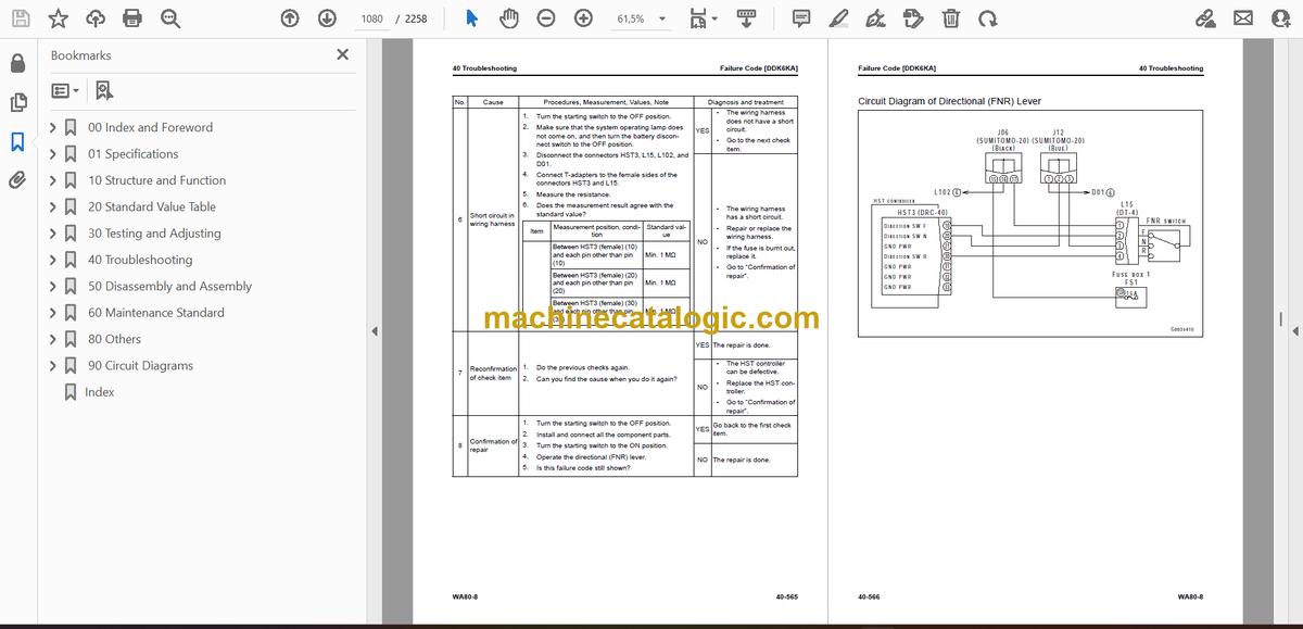
- Failure Code [DDK6KY]
- Failure Code [DF10KA]
- Failure Code [DF10KB]
- Failure Code [DGH1KX]
- Failure Code [DHH1KX]
- Failure Code [DHH1KY]
- Failure Code [DHS5KX]
- Failure Code [DHS5KY]
- Failure Code [DHTCL6]
- Failure Code [DJF1KA]
- Failure Code [DLM3KA]
- Failure Code [DLM3LC]
- Failure Code [DLT3KX]
- Failure Code [DLT4KX]
- Failure Code [DLT4L0]
- Failure Code [DLT4LC]
- Failure Code [DV00KY]
- Failure Code [DWK0KA]
- Failure Code [DWK0KB]
- Failure Code [DWK0KY]
- Failure Code [DX19KA]
- Failure Code [DX19KB]
- Failure Code [DX19KY]
- Failure Code [DXH7KA]
- Failure Code [DXH7KB]
- Failure Code [DXH7KY]
- Failure Code [DXH8KA]
- Failure Code [DXH8KB]
- Failure Code [DXH8KY]
- Failure Code [J141N1]
- Failure Code [LA00L3]
- Failure Code [M100N1]
- Failure Code [M400N1]
- Troubleshooting of Electrical System (E-Mode)
- Engine Does Not Start (Engine Does Not Crank)
- Manual Preheating System Does Not Operate
- Automatic Preheating System Does Not Operate
- While Preheating is in Operation, Preheating Monitor Does Not Come On
- Machine Monitor Shows Nothing When Starting Switch is Turned to ON Position
- The Bucket Positioner Does Not Work or Cannot be Released
- Fan Does Not Rotate in Reverse
- Front Wiper Does Not Operate
- Rear Wiper Does Not Operate
- Window Washer Does Not Operate
- Headlamp, Clearance Lamp, Tail Lamp, and License Plate Lamp Do Not Come On
- Both High and Low Beams of Headlamp Do Not Come On or Go Off
- Low Beam of Headlamp Does Not Come On or Go Off
- High Beam of Headlamp Does Not Come On or Go Off
- Clearance Lamp, Tail Lamp, and License Plate Lamp Do Not Come On or Go Off
- Front Working Lamp Does Not Come On or Go Off
- Rear Working Lamp Does Not Come On or Go Off
- All of Turn Signal Lamps and Hazard Lamps Do Not Come On or Go Off
- Turn Signal Lamp Does Not Come On or Go Off
- Hazard Lamp Does Not Come On or Go Off
- Brake Lamp Does Not Come On or Stays Lit
- Backup Lamp Does Not Come On or Stays Lit
- Backup Buzzer Does Not Sound or Continues to Sound
- Horn Does Not Sound or Continues to Sound
- Alarm Buzzer Does Not Sound or Continues to Sound
- KOMTRAX System Does Not Operate Correctly
- Diagram Related to KOMTRAX System
- Troubleshooting for Hydraulic and Mechanical Systems (H Mode)
- Information Shown in Troubleshooting Table (H-Mode)
- Failure Mode and Cause Table
- Does Not Travel Forward or Reverse
- Does Not Travel Forward (Reverse is Normal)
- Does Not Travel in Reverse (Forward is Normal)
- Slow Travel Speed in Both Forward and Reverse
- Slow Travel Speed in Forward (Reverse is Normal)
- Slow Travel Speed in Reverse (Forward is Normal)
- Not Sufficient Drawbar Pull in Both Forward and Reverse
- Not Sufficient Drawbar Pull in Forward (Reverse is Normal)
- Not Sufficient Drawbar Pull in Reverse (Forward is Normal)
- Engine Speed Decreases Significantly or Engine Stops During Travel
- Machine Does Not Turn
- Steering Wheel is Heavy to Operate
- Machine Wanders or Large Shocks Occur During Steering
- Machine Unintentionally Turns to One Side When Machine Travels
- Wheel Brakes Do Not Operate or are Weak
- Wheel Brakes are Not Released or Drag
- Parking Brake Does Not Operate or is Weak
- Parking Brake is Not Released or Drags
- Boom Does Not Rise
- Boom Moves Slow or Lacks Lifting Force
- Rising Boom Slows Down at Specified Height
- Lift Cylinder Cannot Hold Bucket (Bucket Floats Up)
- Hydraulic Drift of Boom is Large
- Boom Moves Up and Down During Operation
- Bucket Does Not Tilt Back
- Bucket Moves Slow or Lacks Tilt-Back Force
- Bucket Slows Down During Tilt Back Operation
- Bucket Cylinder Cannot Hold Bucket (Bucket Floats Up)
- Hydraulic Drift of Bucket is Large
- Bucket Tilts Back and Forth When You Carry Load (Work Equipment Valve is in Hold)
- Boom and Bucket Control Levers Do Not Move Smoothly and are Heavy to Move
- Engine Speed Drops Largely or Engine Stops When You Operate Work Equipment
- Large Shocks are Made When Work Equipment Starts to Move and Stops
- Abnormal Fan Speed (High, Low, or Not Rotating)
- Unusual Noise is Heard from Around Fan
- Troubleshooting of Engine (S-Mode)
- Information Shown in Troubleshooting Table (S-Mode)
- Engine Does Not Crank When Starting Switch is Turned to Start Position
- Engine Cranks but Does Not Start
- Fuel is Sprayed but Engine Does Not Start (Misfiring: Engine Cranks but Does Not Start)
- Engine Startability is Unsatisfactory
- Engine Does Not Pick Up Smoothly
- Engine Stops During Operation
- Engine Does Not Rotate Smoothly
- Engine Lacks Output (or Lacks Power)
- Exhaust Smoke is Black
- Engine Oil Consumption is Excessive
- Engine Oil Becomes Dirty Quickly
- Fuel Consumption is High
- Oil is in Coolant (or Coolant Spurts Back or Coolant Level Goes Down)
- Engine Oil Pressure Drops
- Fuel Mixes into Engine Oil
- Water Mixes Into Engine Oil (Milky)
- Coolant Temperature Increases Too High (Overheat)
- Unusual Noise is Heard
- Vibration is Excessive
- Air Cannot be Bled from Fuel Circuit
- 50 Disassembly and Assembly
- Table of Contents
- Precautions Before Work
- Related Information on Disassembly and Assembly
- How to Read This Manual
- Coating Materials List
- Special Tool List
- Sketches of Special Tools
- Engine and Cooling System
- Remove and Install Supply Pump Assembly
- How to Remove Supply Pump Assembly
- How to Install Supply Pump Assembly
- Remove and Install Injector Assembly
- How to Remove Injector Assembly
- How to Install Injector Assembly
- Remove and Install Cylinder Head Assembly
- How to Remove Cylinder Head Assembly
- How to Install Cylinder Head Assembly
- Remove and Install EGR Valve Assembly
- How to Remove EGR Valve Assembly
- How to Install EGR Valve Assembly
- Remove and Install EGR Cooler Assembly
- How to Remove EGR Cooler Assembly
- How to Install EGR Cooler Assembly
- Remove and Install Starting Motor Assembly
- How to Remove Starting Motor Assembly
- How to Install Starting Motor Assembly
- Remove and Install Alternator and Air Conditioner Compressor Belt
- How to Remove Alternator and Air Conditioner Compressor Belt
- How to Install Alternator and Air Conditioner Compressor Belt
- Remove and Install Alternator Assembly
- How to Remove Alternator Assembly
- How to Install Alternator Assembly
- Remove and Install Auto-Tensioner
- How to Remove Auto-Tensioner
- How to Install Auto-Tensioner
- Remove and Install Cooling Assembly
- How to Remove Cooling Assembly
- How to Install Cooling Assembly
- Remove and Install Radiator Assembly
- How to Remove Radiator Assembly
- How to Install Radiator Assembly
- Remove and Install Hydraulic Oil Cooler Assembly
- How to Remove Hydraulic Oil Cooler Assembly
- How to Install Hydraulic Oil Cooler Assembly
- Remove and Install Aftercooler Assembly
- How to Remove Aftercooler Assembly
- How to Install Aftercooler Assembly
- Remove and Install Engine, HST Pump, and Triplex Gear Pump Assembly
- How to Remove Engine, HST Pump, and Triplex Gear Pump Assembly
- How to Install Engine, HST Pump, and Triplex Gear Pump Assembly
- Remove and Install Engine Front Oil Seal
- How to Remove Engine Front Oil Seal
- How to Install Engine Front Oil Seal
- Remove and Install Engine Rear Oil Seal
- How to Remove Engine Rear Oil Seal
- How to Install Engine Rear Oil Seal
- Remove and Install Cooling Fan and Fan Motor Assembly
- How to Remove Cooling Fan and Fan Motor Assembly
- How to Install Cooling Fan and Fan Motor Assembly
- Remove and Install KDOC Assembly
- How to Remove KDOC Assembly
- How to Install KDOC Assembly
- Remove and Install KCCV Assembly
- How to Remove KCCV Assembly
- How to Install KCCV Assembly
- Remove and Install Turbo Charger Assembly
- How to Remove Turbo Charger Assembly
- How to Install Turbo Charger Assembly
- Remove and Install Engine Hood Assembly
- How to Remove Engine Hood Assembly
- How to Install Engine Hood Assembly
- Remove and Install Fuel Tank Assembly
- How to Remove Fuel Tank Assembly
- How to Install Fuel Tank Assembly
- Remove and Install Air Cleaner Assembly
- How to Remove Air Cleaner Assembly
- How to Install Air Cleaner Assembly
- Remove and Install Air Conditioner Compressor Assembly
- How to Remove Air Conditioner Compressor Assembly
- How to Install Air Conditioner Compressor Assembly
- Remove and Install Air Conditioner Condenser Assembly
- How to Remove Air Conditioner Condenser Assembly
- How to Install Air Conditioner Condenser Assembly
- Power Train
- Remove and Install HST Pump and Triplex Gear Pump Assembly
- How to Remove HST Pump and Triplex Gear Pump Assembly
- How to Install HST Pump and Triplex Gear Pump Assembly
- Remove and Install Transfer and HST Motor Assembly
- How to Remove Transfer and HST Motor Assembly
- How to Install Transfer and HST Motor Assembly
- Disconnect and Connect Transfer and HST Motor Assembly
- How to Disconnect Transfer and HST Motor Assembly
- How to Connect Transfer and HST Motor Assembly
- Remove and Install Parking Brake Assembly
- How to Remove Parking Brake Assembly
- Install Parking Brake Assembly
- Remove and Install Front Axle Assembly
- How to Remove Front Axle Assembly
- How to Install Front Axle Assembly
- Remove and Install Rear Axle Assembly
- How to Remove Rear Axle Assembly
- How to Install Rear Axle Assembly
- Disassemble and Assemble Transfer Assembly
- Disassemble Transfer Assembly
- Assemble Transfer Assembly
- Disassemble and Assemble Differential Assembly
- How to Disassemble Differential Assembly
- How to Assemble Differential Assembly
- Disassemble and Assemble Axle Housing Assembly
- How to Disassemble Axle Housing Assembly
- How to Assemble Axle Housing Assembly
- Undercarriage and Frame
- Remove and Install Center Hinge Pin
- How to Remove Center Hinge Pin
- How to Install Center Hinge Pin
- Remove and Install Counterweight Assembly
- How to Remove Counterweight Assembly
- How to Install Counterweight Assembly
- Hydraulic System
- Remove and Install Hydraulic Tank Assembly
- How to Remove Hydraulic Tank Assembly
- How to Install Hydraulic Tank Assembly
- Remove and Install Control Valve Assembly
- How to Remove Control Valve Assembly
- How to Install Control Valve Assembly
- Work Equipment
- Disassemble and Assemble Hydraulic Cylinder Assembly
- How to Disassemble Hydraulic Cylinder Assembly
- How to Assemble Hydraulic Cylinder Assembly
- Remove and Install Work Equipment Assembly
- How to Remove Work Equipment Assembly
- How to Install Work Equipment Assembly
- CAB Related Parts
- Remove and Install Operator Cab Assembly
- How to Remove Operator Cab Assembly
- How to Install Operator Cab Assembly
- Remove and Install Canopy Assembly
- How to Remove Canopy Assembly
- How to Install Canopy Assembly
- Remove and Install Operator Cab Glass (Adhered Glass)
- How to Remove Operator Cab Glass (Adhered Glass)
- How to Install Operator Cab Glass (Adhered Glass)
- Remove and Install Air Conditioner Unit Assembly
- How to Remove Air Conditioner Unit Assembly
- How to Install Air Conditioner Unit Assembly
- Remove and Install Operator Seat
- How to Remove Operator Seat
- How to Install Operator Seat
- Remove and Install Seat Belt
- How to Remove Seat Belt
- How to Install Seat Belt
- Electrical System
- Remove and Install Engine Controller Assembly
- How to Remove Engine Controller Assembly
- How to Install Engine Controller Assembly
- Remove and Install HST Controller Assembly
- How to Remove HST Controller Assembly
- How to Install HST Controller Assembly
- Remove and Install Machine Monitor Assembly
- How to Remove Machine Monitor Assembly
- How to Install Machine Monitor Assembly
- Remove and Install KOMTRAX Terminal Assembly
- How to Remove KOMTRAX Terminal Assembly
- How to Install KOMTRAX Terminal Assembly
- Remove and Install KCCV Crankcase Pressure Sensor
- How to Remove KCCV Crankcase Pressure Sensor
- How to Install KCCV Crankcase Pressure Sensor
- 60 Maintenance Standard
- Table of Contents
- Explanation of Terms for Maintenance Standard
- Engine and Cooling System
- Maintenance Standard for Engine Mount
- Maintenance Standard for Damper
- Maintenance Standard for Cooling Fan Motor
- Power Train
- Maintenance Standard for Drive Shaft
- Maintenance Standard for Transfer
- Maintenance Standard for Transfer Mount
- Maintenance Standard for HST Pump
- Maintenance Standard for HST Motor
- Maintenance Standard for Front Axle
- Maintenance Standard for Rear Axle
- Maintenance Standard for Front Differential
- Maintenance Standard for Rear Differential
- Maintenance Standard for Final Drive
- Steering System
- Maintenance Standard for Steering Column
- Maintenance Standard for Steering Cylinder
- Brake System
- Maintenance Standard for Front Brake
- Maintenance Standard for Rear Brake
- Maintenance Standard for Parking Brake
- Undercarriage and Frame
- Maintenance Standard for Frame, Axle Mount and Center Hinge Pin
- Hydraulic System
- Maintenance Standard for Hydraulic Tank
- Maintenance Standard for Steering and Work Equipment, HST Charge, and Cooling Fan Pump
- Work Equipment
- Maintenance Standard for Work Equipment Linkage
- Maintenance Standard for Bucket
- Maintenance Standard for Lift Cylinder
- Maintenance Standard for Bucket Cylinder
- CAB Related Parts
- Maintenance Standard for CAB Mount
- Maintenance Standard for Canopy Mount
- 80 Others
- Table of Contents
- Precautions Before Work
- Air Conditioner System
- Precautions for Refrigerant
- Air Conditioner Component
- Specifications of Air Conditioner
- Structure and Function of Refrigeration Cycle
- Outline of Refrigeration Cycle
- Component Parts of Air Conditioner System
- Compressor
- Structure of Compressor
- Specifications of Compressor
- Function of Compressor
- Condenser
- Structure of Condenser
- Specifications of Condenser
- Function of Condenser
- Receiver Drier
- Structure of Receiver Dryer
- Specifications of Receiver Dryer
- Function of Receiver Dryer
- Air Conditioner Control Panel
- Structure of Air Conditioner Control Panel
- Function of Air Conditioner Control Panel
- Information Shown in Troubleshooting
- Troubleshooting of Air Conditioner System (A-Mode)
- Troubleshooting for Power Supply System (Air Conditioner Does Not Operate)
- Troubleshooting for Blower Motor System (No Air Comes Out or Air Flow is Abnormal)
- Troubleshooting for Temperature Control Function
- Troubleshooting for Air Conditioner Compressor and Cooling System (Electrical System)
- Troubleshooting for Air Conditioner Compressor and Cooling System (Mechanical Systems)
- Troubleshooting for Hot Water Circuit System
- Unusual Noise is Heard from Air Conditioner Related Parts
- Water Leaks from Air Conditioner Related Parts
- Troubleshooting for Fresh/Recirc Air Changeover
- Precautions for Disconnection and Connection of Air Conditioner Piping
- Handle Compressor Oil
- 90 Circuit Diagrams
- Table of Contents
- How to Read the Codes for Electric Cable
- Hydraulic Circuit Diagram
- Symbols Used in Hydraulic Circuit Diagram
- Hydraulic Circuit Diagram
- Hydraulic Circuit Diagram (During Forward + Boom Raise Operation)
- Hydraulic Circuit Diagram (During Reverse + Left Turn + Boom Hold Operation)
- Electrical Circuit Diagram
- Symbols Used in Electric Circuit Diagram
- Electrical Circuit Diagram (1/25)
- Electrical Circuit Diagram (2/25)
- Electrical Circuit Diagram (3/25)
- Electrical Circuit Diagram (4/25)
- Electrical Circuit Diagram (5/25)
- Electrical Circuit Diagram (6/25)
- Electrical Circuit Diagram (7/25)
- Electrical Circuit Diagram (8/25)
- Electrical Circuit Diagram (9/25)
- Electrical Circuit Diagram (10/25)
- Electrical Circuit Diagram (11/25)
- Electrical Circuit Diagram (12/25)
- Electrical Circuit Diagram (13/25)
- Electrical Circuit Diagram (14/25)
- Electrical Circuit Diagram (15/25)
- Electrical Circuit Diagram (16/25)
- Electrical Circuit Diagram (17/25)
- Electrical Circuit Diagram (18/25)
- Electrical Circuit Diagram (19/25)
- Electrical Circuit Diagram (20/25)
- Electrical Circuit Diagram (21/25)
- Electrical Circuit Diagram (22/25)
- Electrical Circuit Diagram (23/25)
- Electrical Circuit Diagram (24/25)
- Electrical Circuit Diagram (25/25)
- Index
Komatsu


