The Komatsu 860E-1K Rigid Dump Truck is a haul truck built for large mine and quarry work, moving serious rock all day. The people who usually reach for a shop manual like CEBM037902 are field techs, dealer service, and mine maintenance crews trying to get a down unit back in the haul cycle. They’re not looking for sales fluff; they need repair steps, test points, and what to check next when a system fault won’t clear. If that’s the situation you’re in, this is the kind of document you’re probably after.
What this manual helps you do
- Trace hydraulic and electric faults on the 860E-1K using system descriptions, wiring information, and diagnostic flows you’d expect in a shop manual.
- Check engine, drivetrain, and brake system issues with step‑by‑step workshop‑style procedures instead of just operator‑level tips.
- Follow disassembly and reassembly sequences for major components so you don’t guess at order of operations or miss hidden fasteners.
- Diagnose sensor, control, and monitoring problems on the truck’s electronic systems using the kind of guidance most shops rely on.
- Handle scheduled heavy maintenance and component change‑outs with the repair procedures you’d normally see in a Komatsu shop manual.
Who this is for
This Komatsu 860E-1K Rigid Dump Truck Shop Manual is aimed at field technicians, shop mechanics, and mine or fleet maintenance managers who actually turn wrenches or direct repairs. If you’re just operating the truck and want basic checks or warning light meanings, you’d be better off with the Operation & Maintenance manual instead.
FAQ
Q: Is this a PDF I can download and search?
A: Yes, it’s a digital PDF you can download, search by keyword, and print specific sections for use in the shop or on site.
Q: Is it detailed enough for full teardown work?
A: This kind of shop manual usually walks you through diagnostic procedures, repair workflows, and teardown/assembly steps for workshop‑level jobs.
Q: How do I know it matches my exact 860E-1K truck?
A: Check your machine’s model designation and compare it to 860E-1K, then match the book reference CEBM037902 against what your dealer or site documentation lists.
Bottom line: if you’re responsible for diagnosing and repairing a Komatsu 860E-1K haul truck, this shop manual is what you want; if you only need basic operating guidance, keep looking for the O&M manual instead.
📘 Show Index
Table of Contents:
- COVER
- 00 CONTENTS AND FOREWORD
- Foreword
- How to Read the Shop Manual
- Safety Alert Symbol and Signal Words
- General Precautions Common to Operation and Maintenance
- Preparations for Safe Operation
- Fire and Explosion Prevention
- Precautions When Getting On or Off the Machine
- Precautions for Cab and Working Around Machine
- Precautions for Diesel Exhaust Fluid (DEF)
- Operation Precautions
- Precautions at Jobsite
- Precautions in Starting Engine
- Precautions During Operation
- Maintenance Precautions
- Precautions Before Inspection and Maintenance
- Precautions During Inspection and Maintenance
- Precautions for Electrical Equipment
- Primary Causes of Wiring Harness Failure
- Hydraulic Equipment Precautions
- 01 SPECIFICATIONS
- Specifications
- Specifications: 860E-1K
- Recommended Fuel, Coolant, and Lubricant
- Mixing Rate of Water and Antifreeze
- Wheel Motor Oil Specifications
- Suspension Cylinder Oil and Nitrogen Specifications
- 10 STRUCTURE AND FUNCTION
- Steering System
- Steering System Layout
- Steering System Operation
- Steering Bleeddown Manifold
- Steering Control Unit
- Steering Accumulators (Piston Type)
- Steering/Brake Pump Operation
- Flow Amplifier Operation
- Hoist System
- Hoist System Layout
- Hoist System Operation
- Hoist Control Valve
- Hoist Pilot Valve
- Brake System
- Brake System Layout
- Hydraulic Brake Cabinet Layout
- Rear Axle Brake Components
- Service Brake Operation
- Parking Brake Operation
- Brake Lock Operation
- Secondary Braking and Auto Apply
- Electrical System, 24V
- Battery Power Supply
- Battery Disconnect Switches
- Auxiliary Control Cabinet Components
- Relay Boards
- Automatic Lubrication (Auto Lube) System
- Automatic Lubrication (Auto Lube) Grease Pump and Reservoir
- Automatic Lubrication (Auto Lube) System Operation
- Suspensions
- SIBAS® IGBT Rack Components
- SiBAS®32 Traction Control Unit (TCU)
- Overview of the SiBAS®32 Systems Cards
- SiBAS®32 Cards Removal
- SiBAS®32 Cards Installation
- SiBAS®32 Card Device Names
- Structure of SiBAS®32 Card Part Number
- SiBAS®32 Card Interchangeability
- SiBAS®32 Card Interactions
- SiBAS®32 Card Detailed Information
- CPU Card
- DSP Card
- I/O Card
- TRACO Card (Optional)
- Input Voltage/Frequency Card
- I/O Analog Card
- Reserve Engine Oil System
- Reserve Engine Oil System General Information
- Reserve Engine Oil System Operation
- Remote Tank Fill System
- Wheel Motor Transmission
- Wheel Motor Transmission General Information
- 20 STANDARD VALUE TABLE
- 30 TEST AND ADJUST
- Hydraulic Systems
- Hydraulic System Checkout Procedures
- Hydraulic System Checkout Sheet
- Steering System Leakage Check
- Toe-In Adjustment
- Hoist Cylinder Leakage Test
- Steering Cylinder Leakage Test
- Checking the Steering/Brake Pump Control Pressures
- Adjusting the Steering/Brake Pump Control Pressures
- High Altitude Steering/Brake Pump Adjustment
- Brake System
- Brake System Checkout Procedures
- Brake System Checkout Procedure
- Brake System Checkout Sheet
- Service Brake Piston Leakage Test
- Brake Seal Pressure Test
- Wet Disc Brake Bleeding Procedure
- Parking Brake Leakage Test
- Wet Disc Brake Wear Inspection
- Brake Valve Bench Test and Adjustment
- Bench Test Setup Procedure
- Brake Valve Output Pressure Adjustment
- Final Test and Adjustment
- Accumulators and Suspensions
- Bladder Accumulator Charging Procedure
- Bladder Accumulator Leakage Test
- Bladder Accumulator Storage
- Piston Accumulator Charging Procedure
- Piston Accumulator Leakage Test
- Piston Accumulator Storage
- Check for Improper Suspension Charge
- Suspension Oiling and Charging Procedures
- Oiling and Charging Tools and Support Blocks
- Nitrogen Charging Kit Installation
- Nitrogen Charging Kit Removal
- Front Suspension Oiling and Charging
- Rear Suspension Oiling and Charging
- Suspension Pressure Test
- Automatic Lubrication (Auto Lube) System
- Prime the Auto Lube Pump
- Prime the Auto Lube Grease Lines
- Auto Lube System Checkout
- Adjust the Auto Lube Cycle Timing
- Cab Air Conditioning
- Refrigerant Leak Detection
- A/C System Performance Test
- Check the A/C System Oil
- A/C System Flushing Procedure
- Manifold Gauge Set Installation
- Refrigerant: Recycled vs Reclaimed
- Refrigerant Recovery Procedure
- Evacuate the A/C System
- Charge the A/C System
- Interface Module 2 (IM2)
- Interface Module 2 Software and Tools
- Program the IM2 Controller
- Interface Module 2 Checkout Procedures
- Check for IM Fault Codes
- Checking Digital Inputs to the IM2
- Checking Analog Inputs to the IM2
- Checking Serial Communication to the IM
- Checking Outputs from the IM2
- Interface Module 2 Checkout Sheet
- Payload Meter IV
- Payload Meter IV Software and Tools
- Payload Meter IV System Configuration
- Configuring a Static IP Address
- Payload Meter IV Software Installation
- Payload Meter IV Data Downloading
- Payload Meter IV Checkout Procedure
- Payload Meter IV Checkout Sheet
- KOMTRAX Plus II
- KOMTRAX Plus II Software and Tools
- Komtrax Plus II Controller Ethernet Connection
- KOMTRAX Plus II Configuration
- GPS Connection Test
- Satellite Connection Test
- Komtrax Plus II System Initialization
- Komatsu Wireless Bridge (KWB)
- Komatsu Wireless Bridge Software and Tools
- Bullet Wireless Radio Configuration
- Bullet Wireless Radio Installation
- NanoStation Access Point Configuration
- NanoStation Access Point Connection Test
- IGBT Haul Truck SIBAS® User Manual, Part 1
- Abbreviations
- Precautions
- Customer Monitor For SIBAS® 32 Control Units
- Installing the Customer Monitor
- Calling Up the Customer Monitor
- Operating the Customer Monitor
- IGBT Haul Truck SIBAS® User Manual, Part 2
- Traco Menu
- HW-Traco
- SW-Traco
- DAC-Traco
- Events Menu
- STatistics
- History
- LEL:Last EvL
- LES:Last EvS
- DLL:DC,LastL
- DLS:DC,LastS
- DAL:DC,All L
- DAS:DC,All S
- ML:Memory L
- MS:Memory S
- CN:Clear Norm
- CA:Clear All
- Test-Code
- DS:Diag-Strc
- User Menu
- DAC_IO
- OPerat.Data
- Gear_test
- Acc_test
- Engine_test
- X_Test_Inx
- STate intern
- Pedal calib
- Language
- OFFline-test
- Variables
- IV:Vehic-ID
- Commands
- Settings
- Parameters
- Temp_prot
- Appendix
- Installing ZR / DSP Software
- Monitor Program – Loading software into the SIBAS®
- Loading Software Into The DSP
- Loading A DSP Program Inverter A
- Loading A DSP Program Inverter B
- Loading Software Into The CPU
- Loading ZR Software Prog. Jumpers Reset
- Loading The Proper Pgm File
- Setting The System Up After Loading A New Pgm
- Electrical System, 24V
- Body-up Switch Adjustment
- Hoist Limit Switch Adjustment
- Body-Up Switch Adjustment
- Adjust Hoist Limit Switch
- 40 TROUBLESHOOTING
- Fuse and Circuit Breaker Locations
- Standard Truck Fault Codes
- A001
- A002
- A003
- A004
- A005
- A006
- A007
- A008
- A009
- A010
- A011
- A013
- A014
- A016
- A017
- A018
- A019
- A022
- A100
- A101
- A105
- A111
- A115
- A117
- A118
- A126
- A127
- A128
- A139
- A145
- A146
- A152
- A153
- A154
- A155
- A158
- A159
- A164
- A166
- A167
- A168
- A169
- A170
- A171
- A172
- A173
- A182
- A183
- A184
- A190 (A30003 only)
- A190 (A30004 & Up)
- A194
- A195
- A196
- A197
- A198
- A199
- A200
- A201
- A202
- A203
- A204
- A205
- A206
- A207
- A213
- A214
- A215
- A216
- A223
- A230
- A231
- A233
- A235
- A236
- A237
- A238
- A239
- A240
- A242
- A243
- A244
- A245
- A246
- A247
- A248
- A249
- A250
- A251
- A252
- A253
- A254
- A256
- A257
- A258
- A260
- A261
- A262
- A264
- A265
- A266
- A267
- A268
- A270
- A271
- A272
- A273
- A274
- A275
- A277
- A278
- A279
- A280
- A281
- A282
- A283 (A30004 & Up)
- A284 (A30004 & Up)
- A285 (A30004 & Up)
- A286 (A30004 & Up)
- A292 (A30004 & Up)
- A295
- A296
- A297
- A298
- A299
- A300
- A301
- A302
- A303
- A304
- A305
- A309
- A310
- A311
- A312
- A313
- A315
- A316
- A317
- A318
- A328
- A335
- A350
- A351
- A352 (A30003)
- A352 (A30004 & Up)
- A353
- A354
- A355
- A356
- A357
- A358
- A359
- A360
- A361 (A30003)
- A361 (A30004 & Up)
- A362
- A363
- A364
- A365
- A368
- A369
- A370
- A371
- A372
- A373
- Drive System Fault Codes
- How to use Drive System Fault Code Table
- Event classification
- 1 L3C SYS: Time slice overflow CPU T1
- 10 L2A SYS: Pulse inhibit/asa inhibit PSU–ONLINE
- 11 L3D SYS: Pulse inhibit/asa inhibit PSU-Start-up
- 12 L1A SYS: SIBAS® blower fault
- 13 L1B SYS: Undervoltage in SIBAS® battery for BRAM
- 14 L3C SYS: SIBAS® power supply failure 24V for pulse amplifier.
- 15 L3C SYS: SIBAS® power supply failure +5V
- 16 L3C SYS: SIBAS® power supply failure +15V
- 17 L3C SYS: SIBAS® power supply failure –15V
- 18 L3C SYS: SIBAS® power supply failure +24V
- 19 L3C SYS: SIBAS® power supply failure –24V
- 20 L3C SYS: SIBAS® power supply failure primary
- 21 L3C SYS: FPGA clock missing for PSU
- 22 L3C SYS: Pulse inhibit by reset in PSU from CPU
- 24 L3C SYS: General protection error (G10)
- 25 L3C SYS: Total block
- 26 L1B SYS: Permanent inhibit fault active
- 27 L1B SYS: Regular inhibit fault active
- 28 L1A SYS: GW Test stopped by A/D converter faulty
- 30 L3C DSP A: Initialization fault detected by DSP
- 31 L3C DSP A: SW-Watchdog
- 32 L3C DSP A: Initialization fault detected by CPU
- 33 L1B DSP A: SW-Traco triggered
- 34 L1B DSP A: SW-Traco full
- 35 L3C DSP A: Time slice overflow T1
- 39 L1A DSP A: Communication HSCX data from DSP B missing
- 40 L1A DSP A: Communication HSCX data from DSP T missing
- 41 L3C DSP A: Current offset during pulse block
- 42 L3C DSP A: Current offset during no pulse block
- 43 L3A DSP A: Overcurrent fault
- 44 L3C DSP A: Current transducer defective phase U
- 45 L3C DSP A: Current transducer defective phase W
- 48 L1A DSP A: Modulation software fault
- 49 L3A DSP A: Active current controller at limit
- 50 L3A DSP A: Active current reference at limit
- 51 L1A DSP A: Braking chopper controller at limit
- 52 L3C DSP A: Phase unbalance too large
- 53 L3A DSP A: Pulse block by DSP software
- 54 L3C DSP A: U/F Card defective
- 55 L3C DSP A: Difference in current of phase U over limit
- 56 L3C DSP A: Difference in current of phase W over limit
- 60 L3C DSP B: Initialization fault detected by DSP
- 61 L3C DSP B: SW-Watchdog
- 62 L3C DSP B: Initialization fault detected by CPU
- 63 L1B DSP B: SW-Traco triggered
- 64 L1B DSP B: SW-Traco full
- 65 L3C DSP B: Time slice overflow T1
- 69 L1A DSP B: Communication HSCX data from DSP A missing
- 70 L1A DSP B: Communication HSCX data from DSP T missing
- 71 L3C DSP B: Current offset during pulse block
- 72 L3C DSP B: Current offset during no pulse block
- 73 L3A DSP B: Overcurrent fault
- 74 L3C DSP B: Current transducer defective phase V
- 75 L3C DSP B: Current transducer defective phase W
- 78 L1A DSP B: Modulation software fault
- 79 L3A DSP B: Active current controller at limit
- 80 L3A DSP B: Active current reference at limit
- 81 L1A DSP B: Braking chopper controller at limit
- 82 L3C DSP B: Phase unbalance too large
- 83 L3A DSP B: Pulse block by DSP software
- 84 L3C DSP B: U/F Card defective
- 85 L3C DSP B: Difference in current of phase V over limit
- 86 L3C DSP B: Difference in current of phase W over limit
- 90 L3C DSP T: Initialization fault detected by DSP
- 91 L3C DSP T: SW-Watchdog
- 92 L3C DSP T: Initialization fault detected by CPU
- 93 L1B DSP T: SW-Traco triggered
- 94 L1B DSP T: SW-Traco full
- 95 L3C DSP T: Time slice overflow T1
- 99 L1A DSP T: Communication HSCX data from DSP A missing
- 100 L1A DSP T: Communication HSCX data from DSP B missing
- 101 L3C DSP T: Current offset during pulse block
- 102 L3C DSP T: Current offset during no pulse block
- 103 L3A DSP T: Overcurrent fault
- 104 L3C DSP T: Current transducer defective phase U
- 105 L3C DSP T: Current transducer defective phase V
- 106 L3C DSP T: Current transducer defective phase W
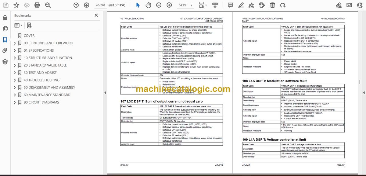
- 107 L3C DSP T: Sum of output current not equal zero
- 108 L1A DSP T: Modulation software fault
- 109 L1A DSP T: Voltage controller at limit
- 112 L3C DSP T: Phase unbalance too large
- 113 L3A DSP T: Pulse block by DSP software
- 114 L3C DSP T: U/F Card defective
- 117 L3C DSP T: Crowbar fired by DSP T
- 119 L1C DSP T: Voltage transducer U34 not ok
- 120 L3C IO: Supervision bus clock
- 121 L3C IO: Supervision I/O clock
- 122 L3C IO: Incorrect FPGA version identifier
- 123 L3C IO: Incorrect FPGA application version identifier
- 124 L3C IO: Incorrect module version identifier
- 125 L3C/L1A IO: AD Converter faulty
- 126 L3C IO: GW Comparator faulty during start-up test
- 127 L3C IO: Test voltage not equal zero
- 128 L1A IO: SIBAS® Temperature out of range
- 129 L3C IO: Incorrect EBIN card identifier
- 130 L3C IO: Front plug monitoring
- 131 L3C IO: CPU Watchdog triggered
- 132 L3C IO: DSP A Watchdog triggered
- 133 L3C IO: DSP B Watchdog triggered
- 134 L3C IO: DSP T Watchdog triggered
- 135 L3C IO: CPU Reset triggered
- 138 L1B IO: CPU Traco triggered
- 146 L3A IO: Pulse block from I/O
- 150 L3A IO: DC link voltage A level 1 exceeded
- 151 L3A IO: DC link voltage B level 1 exceeded
- 152 L3C IO: Trolley line overvoltage
- 154 L3B IO: Trolley line overcurrent
- 155 L2B IO: Trolley line current transducer faulty
- 156 L2B IO: Trolley line voltage transducer faulty
- 160 L3A IO: Throttle pedal out of range
- 161 L3A IO: Retard pedal out of range
- 162 L1A IO: Cruise speed control module out of range
- 180 L3C UWSA1: Supervision bus clock
- 181 L3C UWSA1: Supervision module clock
- 182 L3C UWSA1: Incorrect FPGA version identifier
- 183 L3C UWSA1: Incorrect FPGA project identifier
- 184 L3C UWSA1: GW Comparator faulty during start-up test
- 185 L1A UWSA1: ADC Faulty
- 186 L3C UWSA1: Configuration failure
- 187 L1A UWSA1: Hardware failure counter / processor
- 188 L3A UWSA1: Peak current protection active
- 189 L3D UWSA1: Peak current protection pulse start
- 190 L3D UWSA1: Number of peak current protection >limit
- 191 L3D UWSA1: Supervision switching frequency
- 193 L1A UWSA1: Overvoltage level 1 exceeded
- 196 L3D UWSA1: Limit 5 overcurrent phase U
- 199 L3D UWSA1: Limit 5 overvoltage DC bus
- 201 L3D UWSA1: Checkback INVA1 L1U faulty
- 210 L3C UWSB1: Supervision bus clock
- 211 L3C UWSB1: Supervision module clock
- 212 L3C UWSB1: Incorrect FPGA version identifier
- 213 L3C UWSB1: Incorrect FPGA project identifier
- 214 L3C UWSB1: GW Comparator faulty during start-up test
- 215 L1A UWSB1: ADC Faulty
- 216 L3C UWSB1: Configuration failure
- 217 L1A UWSB1: Hardware failure counter / processor
- 218 L3A UWSB1: Peak current protection active
- 219 L3D UWSB1: Peak current protection pulse start
- 220 L3D UWSB1: Number of peak current protection >limit
- 221 L3D UWSB1: Supervision switching frequency
- 223 L1A UWSB1: Overvoltage level 1 exceeded
- 226 L3D UWSB1: Limit 5 overcurrent phase V
- 229 L3D UWSB1: Limit 5 overvoltage DC bus
- 231 L3D UWSB1: Checkback INVB1 L1U Faulty
- 240 L3C UWSA2: Supervision bus clock
- 241 L3C UWSA2: Supervision module clock
- 242 L3C UWSA2: Incorrect FPGA version identifier
- 243 L3C UWSA2: Incorrect FPGA project identifier
- 244 L3C UWSA2: GW Comparator faulty during start-up test
- 245 L1A UWSA2: ADC Faulty
- 246 L3C UWSA2: Configuration failure
- 247 L1A UWSA2: Hardware failure counter / processor
- 248 L3A UWSA2: Peak current protection active
- 249 L3D UWSA2: Peak current protection pulse start
- 250 L3D UWSA2: Number of peak current protection >limit
- 251 L3D UWSA2: Supervision switching frequency
- 253 L1A UWSA2: Overvoltage level 1 exceeded
- 256 L3D UWSA2: Limit 5 overcurrent phase U1
- 259 L3D UWSA2: Limit 5 overvoltage DC bus
- 261 L3D UWSA2: Checkback INVA2 L1U faulty
- 270 L3C UWSB2: Supervision bus clock
- 271 L3C UWSB2: Supervision module clock
- 272 L3C UWSB2: Incorrect FPGA version identifier
- 273 L3C UWSB2: Incorrect FPGA project identifier
- 274 L3C UWSB2: GW Comparator faulty during start-up test
- 275 L1A UWSB2: ADC Faulty
- 276 L3C UWSB2: Configuration failure
- 277 L1A UWSB2: Hardware failure counter / processor
- 278 L3A UWSB2: Peak current protection active
- 279 L3D UWSB2: Peak current protection pulse start
- 280 L3D UWSB2: Number of peak current protection >limit
- 281 L3D UWSB2: Supervision switching frequency
- 283 L1A UWSB2: Overvoltage level 1 exceeded
- 286 L3D UWSB2: Limit 5 overcurrent phase V1
- 289 L3D UWSB2: Limit 5 overvoltage DC bus
- 291 L3D UWSB2: Checkback INVB2 L1U Faulty
- 300 L3C UWSST: Supervision bus clock
- 301 L3C UWSST: Supervision module clock
- 302 L3C UWSST: Incorrect FPGA version identifier
- 303 L3C UWSST: Incorrect FPGA project identifieR
- 304 L3C UWSST: GW Comparator faulty during start-up test
- 305 L1A UWSST: ADC Faulty
- 306 L3C UWSST: Configuration failure
- 307 L1A UWSST: Hardware failure counter / processor
- 308 L3A UWSST: Peak current protection active
- 310 L3D UWSST: Number of peak current protection >limit
- 311 L3D UWSST: Supervision switching frequency
- 314 L3C UWSST: Crowbar is fired without command
- 316 L3D UWSST: Limit 5 overcurrent phase U
- 319 L3D UWSST: Limit 5 overvoltage DC bus
- 321 L3D UWSST: Checkback INVST L1U Faulty
- 327 L3C UWSST: Checkback crowbar faulty
- 330 L1A BUS: CAN Communication failure
- 331 L1A BUS: Serial link communication failure
- 332 L1A BUS: Truck is over loaded
- 333 L1B TR: Transient traco is triggered
- 334 L1B TR: Transient traco is full
- 340 L1A ETM: ADC Failure for ETM1
- 341 L1A ETM: ADC Failure for ETM2
- 342 L1A ETM: ADC Failure for ETM3
- 343 L1A ETM: ADC Failure for ETM4
- 344 L1A MEFA: ADC Failure
- 345 L3C HL: Gate unit power supply A defective
- 346 L3C HL: Gate unit power supply B defective
- 351 L1A DRZ: LIMP Mode A active
- 352 L1A DRZ: Limp mode B active
- 353 L1A DRZ: Low battery voltage
- 354 L1B BUS: Engine floor input increasing minimum engine speed
- 355 L1B DM: Data store switch pressed
- 356 L1B DM: Diagnosis memory configuration failure
- 357 L1B DM: Diagnosis memory occupation > 75%
- 358 L1B DM: Diagnosis memory full
- 359 L1B DM: Test event
- 360 L2A EXT: Main blower air flow supervision
- 361 L2A EXT: Minimum engine speed supervision
- 362 L1A EXT: Main blower pressure switch malfunction
- 363 L1A EXT: Shift lever supervision
- 364 L2A EXT: Engine derate protection active
- 365 L1A EXT: Truck external plug monitoring
- 366 L1A EXT: Grid dry mode active
- 367 L3A EXT: DC Power off mod request (rest switch on)
- 368 L1A EXT: Steering encoder defective
- 369 L1A EXT: Doppler sensor defective
- 370 L1A EXT: Auto lube control defective
- 372 L1A EXT: Service brake pressed at high speeD
- 373 L1A EXT: Service brake on above speed limit
- 374 L1A EXT: Anti-roll control malfunctions
- 375 L3B BEF: CB301 Circuit breaker defective
- 376 L3B BEF: K303/K304 Contactor defective
- 377 L3C STP: Voltage reading incorrect between trolley line and voltage in stepdown box
- 382 L3B BEF: K103 Feedback defective
- 383 L3B BEF: K105 Feedback defective
- 384 L1A BEF: K107 Feedback defective
- 385 L1A BEF: K109 Feedback defective
- 386 L1A BEF: K111 Feedback defective
- 387 L1A BEF: Limp mode selector defective
- 388 L2B BEF: CB113 Tripped
- 390 L3D IUW: Output current supervision INV A
- 391 L3D IUW: Output current supervision INV B
- 392 L3B IUW: Precharge supervision 1
- 393 L3B IUW: Precharge supervision 2
- 394 L3A IUW: DC Link undervoltage
- 395 L2B IUW: Trolley line undervoltage
- 397 L3B IUW: Field regulator current setpoint supervision
- 398 L2B IUW: Field regulator output current supervision
- 399 L3B IUW: Alternator overcurrent protection
- 400 L2C IUW: Alternator overload warning
- 401 L2B IUW: Alternator overload protection
- 402 L3C IUW: Alternator AC current sensor faulty
- 403 L2A IUW: DC Link voltage out of range in propel
- 404 L3A IUW: DC Link voltage out of range retard
- 405 L3A IUW: DC Link voltage out of range for ST operation
- 406 L3B IUW: DC Link controller supervision
- 407 L2C IUW: Motor torque square T supervision
- 408 L2C IUW: Motor current square T supervision
- 409 L1A IUW: DC Link discharge time exceeded limit
- 410 L2B IUW: Ground fault at positive DC link detected
- 411 L2B IUW: Ground fault at negative DC link detected
- 412 L2B IUW: Ground fault at AC side detected
- 413 L2B IUW: Ground fault
- 414 L3C IUW: Chopper A current supervision
- 415 L3C IUW: Chopper B current supervision
- 416 L3C IUW: Chopper C current supervision
- 417 L3C IUW: Chopper D current supervision
- 418 L3D IUW: Output current supervision INV ST
- 419 L2A IUW: Vehicle overspeed supervision
- 420 L1A IUW: DC Link voltage sensor A faulty
- 421 L1A IUW: DC Link voltage sensor B faulty
- 422 L3C IUW: ST Inverter failure
- 423 L3B IUW: DC Grid fan circuit failure
- 424 L2B IUW: Cooling water pressure out of range
- 425 L2B IUW: Cooling water level out of range
- 426 L1A IUW: Water pump motor overtemperature
- 427 L1A IUW: Retard limit supervision
- 428 L1A DRZ: Front wheel A speed sensor supervision
- 429 L1A DRZ: Front wheel B speed sensor supervision
- 430 L3D DRZ: Motor A speed sensor supervision
- 431 L3D DRZ: Motor B speed sensor supervision
- 432 L3C DRZ: Alternator speed sensor supervision
- 433 L2A DRZ: Motor A maximum speed exceeded
- 434 L2A DRZ: Motor B maximum speed exceeded
- 435 L1A DRZ: Alternator maximum speed exceeded
- 436 L3A DRZ: Motor A/B rotation inconsistency
- 437 L3A DRZ: Motor A torque supervision
- 438 L3A DRZ: Motor B torque supervision
- 439 L3C SIV: Start-up sequence can't pass due to GUPS failure
- 440 L3C SIV: Start-up sequence can't pass due to K103/K105 failure
- 441 L3C SIV: Start-up sequence can't pass due to IGBT failure
- 442 L3C SIV: Start-up sequence can't pass due to CB301 OR K303 failure
- 443 L3C SIV: Start-up sequence can't pass due to crowbar failure
- 447 L1A SIV: Direct trolley engage sequence supervision
- 448 L1A SIV: Direct trolley disengage sequence supervision
- 450 L1A TMP: SIBAS® Temperature < low limit
- 451 L1A TMP: SIBAS® Temperature > warning limit
- 452 L3B TMP: SIBAS® Temperature > shutdown limit
- 453 L3A TMP: IGBT Module A101 temperature < low limit
- 454 L2C TMP: IGBT Module A101 temperature > APRS limit
- 455 L3A TMP: IGBT Module A101 temperature > shutdown limit
- 456 L3A TMP: IGBT Module A102 temperature < low limit
- 457 L2C TMP: IGBT Module A102 temperature > APRS limit
- 458 L3A TMP: IGBT Module A102 temperature > shutdown limit
- 459 L3A TMP: IGBT Module A201 temperature < low limit
- 460 L2C TMP: IGBT Module A201 temperature > APRS limit
- 461 L3A TMP: IGBT Module A201 temperature > shutdown limit
- 462 L3A TMP: IGBT Module A202 temperature < low limit
- 463 L2C TMP: IGBT Module A202 temperature > APRS limit
- 464 L3A TMP: IGBT Module A202 temperature >shutdown limit
- 465 L3A TMP: ST Module temperature < low limit
- 466 L2C TMP: ST Module temperature > warning limit
- 467 L3A TMP: ST Module temperature > shutdown limit
- 468 L2B TMP: SR Module temperature < low limit
- 469 L2C TMP: SR Module temperature > warning limit
- 470 L2B TMP: SR Module temperature > shutdown limit
- 471 L2C TMP: Wheel motor A stator temperature > APRS limit
- 472 L3A TMP: Wheel motor A stator temperature > shutdown limit
- 473 L2C TMP: Wheel motor B Stator temperature > APRS limit
- 474 L3A TMP: Wheel motor B stator temperature shutdown limit
- 475 L2C TMP: Wheel motor A, DE bearing temperature > warning limit
- 476 L3A TMP: Wheel motor A, DE bearing temperature > shutdown limit
- 477 L2C TMP: Wheel motor A NDE bearing temperature > warning limit
- 478 L3A TMP: Wheel motor A NDE bearing temperature > shutdown limit
- 479 L2C TMP: Wheel motor B DE bearing temperature > warning limit
- 480 L3A TMP: Wheel motor B DE bearing temperature > shutdown limit
- 481 L2C TMP: Wheel motor B NDE bearing temperature > warning limit
- 482 L3A TMP: Wheel motor B NDE bearing temperature > shutdown limit
- 483 L2C TMP: Alternator stator temperature > APRS limit
- 484 L2B TMP: Alternator stator temperature > shutdown limit
- 485 L2C TMP: Alternator bearing temperature > warning limit
- 486 L2B TMP: Alternator bearing temperature > shutdown limit
- 487 L1A TMP: Cooling water inlet temperature < low limit
- 488 L2C TMP: Cooling water inlet temperature > warning limit
- 489 L2B TMP: Cooling water inlet temperature > shutdown limit
- 490 L1A TMP: Cooling water outlet temperature < low limit
- 491 L2C TMP: Cooling water outlet temperature > warning limit
- 492 L2B TMP: Cooling water outlet temperature > shutdown limit
- 493 L1A TMP: Cooling water delta T too high
- 495 L2C TMP: Inverter cab temperature > warning limit
- 496 L2B TMP: Inverter cab temperature > shutdown limit
- 497 L2C TMP: Inside cooler outlet temperature > warning limit
- 498 L2B TMP: Inside cooler outlet temperature > shutdown limit
- 499 L1A TMP: Main blower motor stator temperature > warning limit
- 500 L1A TMP: Main blower motor stator temperature > shutdown limit
- 505 L1A TMP: Wheel motor A rotor temperature > limit
- 506 L1A TMP: Wheel motor B rotor temperature > limit
- 508 L1A ETM1: Alternator PT100 open circuit
- 516 L1A ETM2: Motor A NDE Bearing PT100 open circuit
- 524 L1A ETM3: IGBT Module A101 PT100 open circuit
- 532 L1A ETM3: ST Module PT100 open circuit
- 536 L1A ETM4: Channel 1 PT100 open circuit
- 550 L3A TMP: Inverter A module temperature < low limit
- 551 L2C TMP: Inverter A module temperature > APRS limit
- 552 L3A TMP: Inverter A module temperature > shutdown limit
- 553 L3A TMP: Inverter B module temperature < low limit
- 554 L2C TMP: Inverter B module temperature > APRS limit
- 555 L3A TMP: Inverter B module temperature > shutdown limit
- 556 L3A TMP: Chopper A module temperature < low limit
- 557 L2C TMP: Chopper A module temperature > APRS limit
- 558 L3A TMP: Chopper A module temperature > shutdown limit
- 559 L3A TMP: Chopper B module temperature < low limit
- 560 L2C TMP: Chopper B module temperature > APRS limit
- 561 L3A TMP: Chopper B module temperature > shutdown limit
- Payload Meter Scoreboard
- Display Messages and LED Lights
- Option Switches
- Troubleshooting
- Electric Wheel Motor
- Fault Table – Electric Wheel Motor
- Troubleshoot the Steering System
- Steering System Troubleshooting Guide
- Basic Hydraulic System Checks
- Steering/Brake Pump Troubleshooting Guide
- Steering/Brake Pump Troubleshooting Checks
- Steering/Brake Pump Fails to Unload
- Steering/Brake Pump Fails to Develop Pressure
- Steering/Brake Pump Slow to Develop Pressure
- Steering/Brake Pump Control Valve Inspection
- Steering/Brake Pump Case Drain Check
- Troubleshoot the Cab Air Conditioning
- Preliminary Checks
- Diagnosis of Gauge Readings and System
- Troubleshooting by Manifold Gauge Set Readings
- Troubleshoot the Auto Lube System
- Reserve Engine Oil System
- Circuit fuses
- Pumping unit LED signals
- 50 DISASSEMBLY AND ASSEMBLY
- Special Tools List
- Wheels, Spindles and Rear Axle
- General Precautions for Tires and Rims
- Lubricants for Tire and Rim Service
- Tire Inflation
- Rim Components
- Wheel Stud Maintenance
- Front Wheel Removal
- Front Wheel Installation
- Rear Wheel Removal
- Rear Wheel Installation
- Lock Ring Removal
- Lock Ring Installation
- Smart Lock Ring Removal
- Smart Lock Ring Installation
- Lock Ring Retainer Installation
- Tire Removal (Front 5-Piece Standard Rim)
- Tire Removal (Rear Outer 7-Piece Rim)
- Tire Removal (Rear Inner 5-Piece Rim)
- Tire and Rim Preparation
- Tire Installation (Front 5-Piece Standard Rim)
- Tire Installation (Horizontal Mount – Smart Rim)
- Tire Installation (Vertical Mount – 5-Piece Smart Rim)
- Tire Installation – Vertical Mount (7-Piece Smart Rim)
- Front Wheel Hub and Spindle Removal
- Spindle Removal While Off the Truck
- Front Wheel Hub and Spindle Installation
- Spindle, Hub and Brake Assembly Cross-Section View
- Front Wheel Hub and Spindle Disassembly
- Front Wheel Hub and Spindle Cleaning and Inspection
- Front Wheel Hub and Spindle Assembly
- Floating Seal Installation
- Rear Axle Removal
- Rear Axle Cleaning and Inspection
- Rear Axle Installation
- Anti-Sway Bar Removal
- Anti-Sway Bar Installation
- Pivot Pin Removal
- Pivot Pin Installation
- Pivot Eye Bearing Wear Inspection
- Pivot Eye Bearing Replacement
- Pivot Eye Removal
- Pivot Eye Installation
- Wheel Motor Removal
- Wheel Motor Cleaning and Inspection
- Wheel Motor Installation
- Electric Motor Removal
- Electric Motor Installation
- Wheel Motor Transmission Disassembly
- Wheel Motor Transmission Cleaning and Inspection
- Wheel Motor Transmission Assembly
- Low Speed Carrier Disassembly
- Low Speed Carrier Inspection
- Low Speed Carrier Assembly
- High Speed Carrier Disassembly
- High Speed Carrier Inspection
- High Speed Carrier Assembly
- Steering System
- Steering Control Unit Removal
- Steering Control Unit Installation
- Steering Control Unit Disassembly
- Steering Control Unit Assembly
- Steering Column Removal
- Steering Column Installation
- Steering Wheel Removal
- Steering Wheel Installation
- Bleeddown Manifold Removal
- Bleeddown Manifold Installation
- Flow Amplifier Removal
- Flow Amplifier Installation
- Steering Pin Joint Wear Inspection
- Tie Rod Removal
- Tie Rod Installation
- Steering Cylinder Removal
- Steering Cylinder Installation
- Steering Cylinder Disassembly
- Steering Cylinder Cleaning and Inspection
- Steering Cylinder Assembly
- Steering/Brake Pump Removal
- Steering/Brake Pump Installation
- Piston Steering Accumulator Removal
- Piston Steering Accumulator Installation
- Piston Steering Accumulator Disassembly
- Piston Accumulator Cleaning and Inspection
- Piston Seal Replacement
- Piston Steering Accumulator Assembly
- Brake System
- Brake Treadle Valve Removal
- Brake Treadle Valve Installation
- Brake Valve/Pedal Disassembly
- Brake Valve/Pedal Assembly
- Front Brake Dual Relay Valve Removal
- Front Brake Dual Relay Valve Installation
- Rear Brake Dual Relay Valve Removal
- Rear Brake Dual Relay Valve Installation
- Brake Manifold Removal
- Brake Manifold Installation
- Brake Manifold Component Replacement
- Piston Brake Accumulator Removal
- Piston Brake Accumulator Installation
- Piston Brake Accumulator Disassembly
- Piston Accumulator Cleaning and Inspection
- Piston Seal Replacement
- Piston Brake Accumulator Assembly
- Rear Wheel Brake Removal
- Rear Wheel Brake Installation
- Wheel Brake Components
- Front Wheel Brake Disassembly
- Rear Wheel Brake Disassembly
- Wheel Brake Cleaning and Inspection
- Front Wheel Brake Assembly
- Rear Wheel Brake Assembly
- Hoist System
- Hoist Pump Removal
- Hoist Pump Installation
- Hoist Pump Disassembly
- Hoist Pump Inspection
- Hoist Pump Assembly
- Hoist Control Valve Removal
- Hoist Control Valve Installation
- Hoist Control Valve Service
- Hoist Control Valve O-Ring Replacement
- Inlet Section Disassembly
- Inlet Section Assembly
- Front Spool Section Disassembly
- Front Spool Section Assembly
- Rear Spool Section Disassembly
- Rear Spool Section Assembly
- Overcenter Manifold Service
- Hoist Pilot Valve Removal
- Hoist Pilot Valve Installation
- Hoist Pilot Valve Disassembly
- Hoist Pilot Valve Cleaning and Inspection
- Hoist Pilot Valve Assembly
- Hoist Cylinder Removal
- Hoist Cylinder Installation
- Hoist Cylinder Disassembly
- Hoist Cylinder Cleaning and Inspection
- Quill Installation
- Quill Check Ball and Plug Installation
- Hoist Cylinder Assembly
- Suspensions
- Front Suspension Removal
- Front Suspension Cleaning and Inspection
- Front Suspension Installation
- Front Suspension Bolted Joint Inspection
- Front Suspension Charging Valve Replacement
- Front Suspension Disassembly
- Front Suspension Assembly
- Rear Suspension Removal
- Rear Suspension Installation
- Rear Suspension Charging Valve Replacement
- Rear Suspension Disassembly
- Rear Suspension Cleaning and Inspection
- Rear Suspension Assembly
- Dump Body and Structures
- Dump Body Removal
- Dump Body Inspection
- Dump Body Installation
- Body Pads Removal
- Body Pads Installation
- Body Pad Shimming Procedure
- Diagonal Ladder Removal
- Diagonal Ladder Installation
- Grille and Hood Assembly Removal
- Grille and Hood Assembly Installation
- Egress Gate Adjustment
- RH Deck Removal
- RH Deck Installation
- LH Deck Removal
- LH Deck Installation
- Fuel Tank Removal
- Fuel Tank Cleaning and Inspection
- Fuel Tank Installation
- Fuel Gauge Sender Removal
- Fuel Gauge Sender Installation
- Hydraulic Tank Removal
- Hydraulic Tank Installation
- Hydraulic Tank Strainers Removal
- Hydraulic Tank Strainers Cleaning and Inspection
- Hydraulic Tank Strainers Installation
- Operator Cab
- Operator Cab Removal
- Operator Cab Installation
- Cab Door Removal
- Cab Door Installation
- Door Panel Removal
- Door Panel Installation
- Window Regulator Replacement
- Door Handle Replacement
- Door Seal Replacement
- Door Glass Removal
- Door Glass Installation
- Door Jamb Bolt Adjustment
- Poor Seal When Door Is Closed
- Door Springs Back Open
- Door Handle Plunger Adjustment
- Side Window Glass Removal
- Side Window Glass Installation
- Windshield Glass Removal
- Windshield Glass Installation
- Rear Window Glass Removal
- Rear Window Glass Installation
- Windshield Wiper Motor Removal
- Windshield Wiper Motor Installation
- Windshield Wiper Arm Removal
- Windshield Wiper Arm Installation
- Windshield Wiper Linkage Removal
- Windshield Wiper Linkage Installation
- Operator Seat Removal
- Cab Seat Servicing
- Operator Seat Installation
- Seat Compressor Replacement
- Passenger Seat Removal
- Passenger Seat Installation
- Seat Belt Removal (Standard Seat)
- Seat Belt Installation (Standard Seat)
- Seat Belt Service (Optional Seats)
- Seat Belt Removal (Optional Seat)
- Seat Belt Installation (Optional Seat)
- Power Module
- Power Module General Information
- Power Module Removal
- Power Module Installation
- Exhaust Tube Installation
- Exhaust Blanket Installation
- Alternator Removal
- Alternator Installation
- Engine Flywheel Housing Face Runout
- Crankshaft Endplay
- Engine Flywheel Housing to Flywheel Mating Surface – Measurement C
- Alternator Housing to Rotor – Measurement A
- Measurements After Joining the Alternator and Engine
- Flywheel Housing Radial Runout
- Flywheel Housing Face Runout
- Flywheel/Flexplate Face Runout
- Flywheel/Flexplate Radial Runout
- Rotor Shaft Radial Runout (Assembled)
- Measuring Radial Runout of Flexplate Connected to the Flywheel
- Radiator Removal
- Radiator Installation
- Radiator Internal Inspection
- Radiator External Cleaning
- Radiator Disassembly
- Radiator Cleaning and Inspection
- Radiator Assembly
- Engine Removal
- Engine Service
- Engine Installation
- Three Phase Wheel Motor
- Qualified Personnel
- General Safety
- Handling the Motor
- Transporting the Motor
- Storage of Motors
- Storage of New Motors
- Storage of Used Motors
- Motor Maintenance
- Safety Guidelines While Performing Maintenance
- Maintenance Intervals
- Maintenance Work on the Installed Motor
- Checking for External Damage
- Checking the Connections
- Bearing Greasing
- Applying Grease to the Bearings
- Checking for Water in the Motor
- Motor Disassembly
- Pressing Off the Coupling
- Rotor Disassembly
- Rubber Seal and Air Baffle Removal
- Bearing and Labyrinth Ring Removal
- Maintenance and Inspection
- Motor Assembly
- Rubber Seal and Air Baffle Assembly
- Assembly After Special Repair Work
- Bearing Installation
- Bearing Preparation and Assembly
- Cover Installation
- Assembling the Bearing Shield (N-end) at the Stator Frame
- Bearing Installation
- Rotor Installation
- Labyrinth Ring Installation
- Installing Accessories (D- and N-end)
- Running in the Bearings
- Coupling Installation
- Assembly Conditions and Tests
- Motor Repair
- Recommended Consumables
- Generally Approved Chemical Cleaning Agents
- Chemical Cleaning Agents – Outdoor Use and Mechanical Parts
- Chemical Cleaning Agents – Flange Faces
- Chemical Cleaning Agents – Windings
- Chemical Cleaning Agents – Severely Damaged or Oily Windings
- Rolling-Contact Bearing Grease
- Assembly/Disassembly Agents For Bearing Seat
- Sealants For Joining Parts or Gaps
- Locking Agents For Connecting Elements
- Anti-Corrosion Agent
- Assembly Paste For Temperature Sensors
- List of Tools
- Mounting Devices
- Press For Expanding the Coupling
- Compression Devices For Pressing On or Off
- Pulling Units With Cross Beam or Disk
- Replacing Defective Connecting Leads
- Repairing the Stator Winding Insulation
- Repair Parts List
- Main Blower Motor
- Main Blower Motor Removal
- Main Blower Motor Installation
- Main Blower Motor Disassembly
- Main Blower Motor Assembly
- Retarding Grid
- Retarding Grid Blower Motor Removal
- Retarding Grid Blower Motor Installation
- Retarding Grid Blower Motor Disassembly
- Retarding Grid Blower Motor Assembly
- Retarding Grid Element Removal
- Control Cabinet
- SIBAC Inverter Module Removal
- SIBAC Inverter Module Installation
- Draining And Filling The IGBT Coolant System
- IGBT Coolant Pump Removal
- IGBT Coolant Pump Installation
- 60 MAINTENANCE STANDARD
- Rules for Maintenance
- Torque Specifications
- Shutting Down the Machine
- Hydraulic System Bleeddown Procedure
- Hydraulic System Vacuum Procedure
- Long Term Storage of Electric Dump Truck
- Steering Cylinder Wear Data
- Transmission Wear Data
- Brake Wear Data
- Hydraulic Pumps
- Steering/Brake Pump
- Hoist Pump
- Tie Rod
- Tail Lights, Clearance Lights and Turn Signals
- 90 CIRCUIT DIAGRAMS
Komatsu


