The Komatsu PW180-11E0 Wheeled Excavator is a road‑going excavator used for utility work, road construction, pipe laying, and general civil jobs where you’re moving between sites under its own power. People who reach for the Komatsu PW180-11E0 Wheeled Excavator Shop Manual (VENBM70001-S1) are usually shop mechanics, field techs, and serious fleet owners. They’re trying to do real repairs: engine work, swing issues, boom and arm problems, and hydraulic or electrical faults that basic operator guides just don’t cover.
What this manual helps you do
- Trace hydraulic faults in the work equipment and travel circuits using step‑by‑step test procedures and schematic-based checks.
- Diagnose engine, fuel, and emission control problems with guided troubleshooting trees and inspection sequences.
- Follow correct disassembly and reassembly sequences for major components like boom cylinders, swing machinery, axles, and final drives.
- Check and adjust machine settings, from hydraulic control parameters to electronic monitoring functions, using the procedures these manuals usually spell out.
- Verify wear limits, inspection points, and standard workshop practices so you don’t make common student mistakes like forcing parts or skipping alignment steps.
Who this is for
This shop manual is aimed at field technicians, dealership or independent shop mechanics, and advanced trainees who actually turn wrenches. If you’re just operating the machine or only need daily checks and basic maintenance, you’d be better off with the Operation & Maintenance Manual instead of this shop manual.
FAQ
Q: Is this a PDF I can download and search?
A: Yes, this type of shop manual is normally supplied as a downloadable PDF that you can search and print selected pages for the job.
Q: Is the coverage deep enough for full rebuilds?
A: The Komatsu PW180-11E0 Wheeled Excavator Shop Manual walks through diagnostic procedures, disassembly sequences, and reference data used during workshop-level repairs.
Q: How do I know if it matches my exact machine version?
A: Check that your machine’s model designation matches PW180-11E0 and confirm the book reference VENBM70001-S1 against your dealer’s listing for your serial range or regional variant.
Bottom line: If you’re repairing or diagnosing a PW180-11E0 in a workshop or training setting, this is the right manual; if you only need operating tips and basic service, keep looking for the O&M book instead.
📘 Show Index
Table of Contents:
- VEBM70001-S1.pdf
- Troubleshooting
- Troubleshooting
- Abbreviation List
- List of Abbreviations Used in the Text
- List of Abbreviations Used in the Circuit Diagrams
- Related Information on Troubleshooting
- General Troubleshooting Points
- Troubleshooting Points for UREA SCR System
- In Case Failure Codes Cannot Be Cleared
- Sequence of Events in Troubleshooting
- Checks Before Troubleshooting
- Inspection Procedure Before Troubleshooting
- Preparation for Troubleshooting of Electrical System
- Method for Disconnecting and Connecting Connector With Special Lock
- Procedure for Testing and Troubleshooting
- Information Described in Troubleshooting Table
- Troubleshooting Method for Open Circuit in Wiring Harness of Pressure Sensor System
- Connector Table
- Connector Contact Identification
- T-Branch Box and T-Branch Adapter Table
- T-Boxes and T-adapters Table
- Fuse Location Table
- Precautions for Cleaning and Replacing KDPF (KCSF and KDOC)
- Preparation of Short Circuit Electrical Connector (for Failure Codes [CA1883] and [CA3135])
- Failure Code Table (Display of Code)
- Troubleshooting When Failure Code is Indicated
- Troubleshooting When Failure Code is Indicated
- Troubleshooting by Failure Code (Display of Code)
- Failure Code [2G00MA] – Brake Oil Pressure Abnormality
- Circuit Diagram of Brake Oil Pressure Sensor
- Failure Code [602ENX] – Return Filter Clogging
- Failure Code [6AZ0ZG] – Quick Coupler Pressure Low
- Circuit Diagram of Quick Coupler Pressure Switch
- Failure Code [6B2JMA] – Travel Hydraulic Abnormality
- Failure Code [879AKA] – A/C Recirculation Air Temperature Sensor Open Circuit
- Failure Code [879AKB] – A/C Inner Sensor Short Circuit
- Failure Code [879BKA] – A/C Outer Sensor Open Circuit
- Circuit Diagram of Air Conditioner Fresh Air Temperature Sensor
- Failure Code [879BKB] – A/C Outer Sensor Short Circuit
- Circuit Diagram of Air Conditioner Fresh Air Temperature Sensor
- Failure Code [879CKA] – Ventilating Sensor Open Circuit
- Failure Code [879CKB] – Ventilating Sensor Short Circuit
- Failure Code [879DKZ] – Sunlight Sensor Open or Short Circuit
- Circuit Diagram of Sunlight Sensor
- Failure Code [879EMC] – Ventilation Damper Malfunction
- Failure Code [879FMC] – Air Mix Damper Malfunction
- Failure Code [879GKX] – Refrigerant Abnormality
- Circuit Diagram of Refrigerant (Dual) Pressure Switch
- Failure Code [989L00] – Engine Controller Lock Caution 1
- Failure Code [989M00] – Engine Controller Lock Caution 2
- Failure Code [989N00] – Engine Controller Lock Caution 3
- Failure Code [A1U0N3] – HC Desorb Request 1
- Failure Code [A1U0N4] – HC Desorb Request 2
- Failure Code [A900FR] – Abrupt Engine Stop by Auto Idling Stop 3
- Failure Code [A900N6] – Abrupt Engine Stop by Auto Idling Stop 1
- Failure Code [A900NY] – Abrupt Engine Stop by Auto Idling Stop 2
- Failure Code [AA10NX] – Air Cleaner Clogging
- Failure code [AB00KE] – Charge Voltage Low
- Failure Code [AQ10N3] – Manual Stationary Regeneration Request (KDOC Face Plugging)
- Failure Code [AS00N3] – Manual Stationary Regeneration Request (SCR)
- Failure Code [AS00R2] – Warning 2
- Failure Code [AS00R3] – Inducement 1
- Failure Code [AS00R4] – Inducement 2
- Failure Code [AS00R5] – Inducement 3
- Failure Code [AS00R6] – Temporary Recovery of Inducement
- Failure Code [AS00ZK] – AdBlue/DEF Level Low Error 5
- Failure Code [AS10KM] – AdBlue/DEF Injector Overheat Warning
- Failure Code [AS10NR] – AdBlue/DEF Injector High Temperature Warning
- Failure Code [AS10NT] – AdBlue/DEF Injector Overheat Caution
- Failure Code [B@BAZG] – Engine Oil Pressure Low
- Failure Code [B@BAZK] – Engine Oil Level Low
- Circuit Diagram of Engine Oil Level
- Failure Code [B@BCNS] – Engine Coolant Overheat
- Failure Code [B@BCQA] – Engine Coolant Level Low
- Circuit Diagram of Radiator Coolant Level Switch
- Failure Code [B@BCZK] – Engine Coolant Level Low
- Circuit Diagram of Radiator Coolant Level Switch
- Failure Code [B@HANS] – Hydraulic Oil Overheat
- Circuit Diagram of Hydraulic Oil Temperature Sensor
- Failure Code [CA115] – Engine Neutral and Backup Speed Sensor Error
- Failure Code [CA122] – Charge Air Press Sensor High Error
- Circuit Diagram of Charge Air Pressure Sensor
- Failure Code [CA123] – Charge Air Press Sensor Low Error
- Circuit Diagram of Charge Air Pressure Sensor
- Failure Code [CA131] – Throttle Sensor High Error
- Circuit Diagram of Throttle Sensor
- Failure Code [CA132] – Throttle Sensor Low Error
- Circuit Diagram of Throttle Sensor
- Failure Code [CA144] – Coolant Temperature Sensor High Error
- Circuit Diagram of Coolant Temperature Sensor
- Failure Code [CA145] – Coolant Temperature Sensor Low Error
- Circuit Diagram of Coolant Temperature Sensor
- Failure Code [CA153] – Charge Air Temperature Sensor High Error
- Circuit Diagram of Charge Temperature Sensor
- Failure Code [CA154] – Charge Air Temperature Sensor Low Error
- Circuit Diagram of Charge Temperature Sensor
- Failure Code [CA187] – Sensor 2 Supply Voltage Low Error
- Circuit Diagram of Sensor 2 Supply
- Failure Code [CA221] – Ambient Press Sensor High Error
- Circuit Diagram of Ambient Pressure Sensor
- Failure Code [CA222] – Ambient Press Sensor Low Error
- Circuit Diagram of Ambient Pressure Sensor
- Failure Code [CA227] – Sensor 2 Supply Voltage High Error
- Failure Code [CA234] – Engine Overspeed
- Failure Code [CA238] – NE Speed Sensor Supply Voltage Error
- Circuit Diagram (NE Speed Sensor)
- Failure Code [CA239] – NE Speed Sensor Supply Voltage High Error
- Circuit Diagram (NE Speed Sensor)
- Failure Code [CA249] – Ambient Air Temp Sensor High Error
- Circuit Diagram of Ambient Temperature Sensor
- Failure Code [CA256] – Ambient Air Temp Sensor Low Error
- Circuit Diagram of Ambient Temperature Sensor
- Failure Code [CA271] – IMV or PCV 1 Short Circuit Error
- Circuit Diagram of IMV/PCV1
- Failure Code [CA272] – IMV or PCV 1 Open Circuit Error
- Circuit Diagram of IMV/PCV1
- Failure Code [CA322] – Injector #1 (L#1) Open Circuit Error or Short Circuit Error
- Circuit Diagram of Injector #1
- Failure Code [CA323] – Injector #5 (L#5) Open Circuit Error or Short Circuit Error
- Circuit Diagram of Injector #5
- Failure Code [CA324] – Injector #3 (L#3) Open Circuit Error or Short Circuit Error
- Circuit Diagram of Injector #3
- Failure Code [CA325] – Injector #6 (L#6) Open Circuit Error or Short Circuit Error
- Circuit Diagram of Injector #6
- Failure Code [CA331] – Injector #2 (L#2) Open Circuit Error or Short Circuit Error
- Circuit Diagram of Injector #2
- Failure Code [CA332] – Injector #4 (L#4) Open Circuit Error or Short Circuit Error
- Circuit Diagram of Injector #4
- Failure Code [CA343] – Engine Controller Internal Failure
- Failure Code [CA351] – Injectors Drive Circuit Error
- Failure Code [CA352] – Sensor 1 Supply Voltage Low Error
- Circuit Diagram of Sensor 1 Power Supply
- Failure Code [CA356] – MAF Sensor High Error
- Circuit Diagram (Mass Air Flow Sensor)
- Failure Code [CA357] – MAF Sensor Low Error
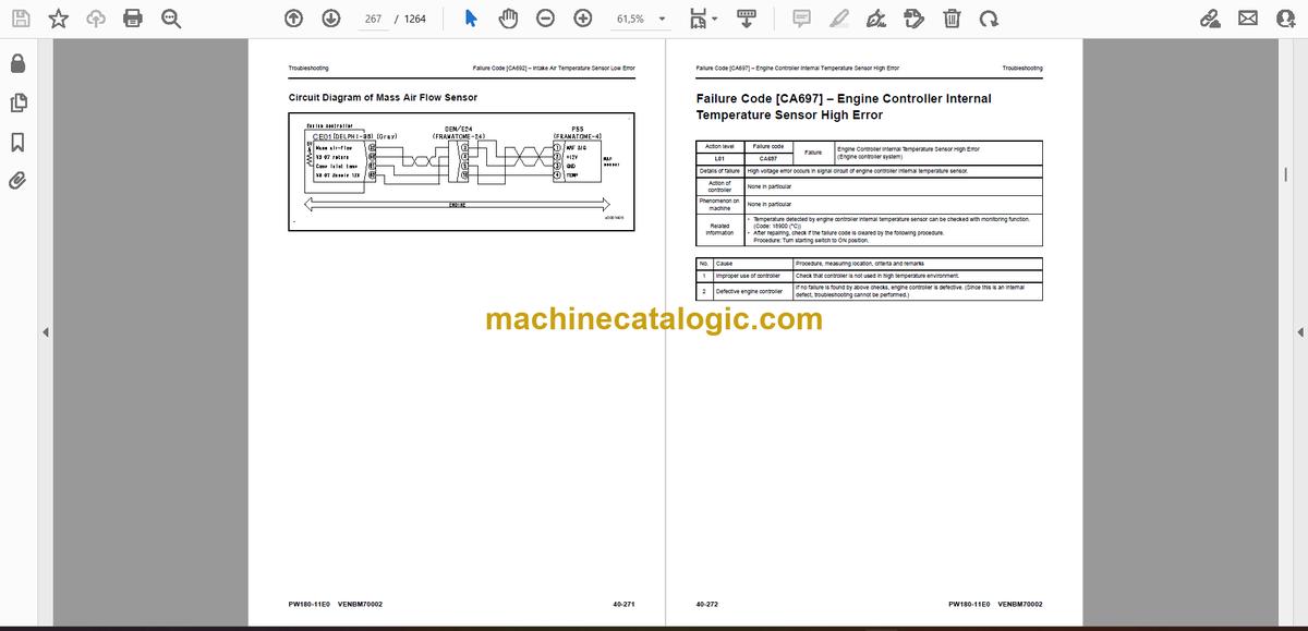
- Circuit Diagram of Mass Air Flow Sensor
- Failure Code [CA386] – Sensor 1 Supply Voltage High Error
- Failure Code [CA428] – Water in Fuel Sensor High Error
- Circuit Diagram of Water-in-Fuel Sensor
- Failure Code [CA429] – Water in Fuel Sensor Low Error
- Circuit Diagram of Water-in-Fuel Sensor
- Failure Code [CA435] – Engine Oil Pressure SW Error
- Circuit Diagram of Engine Oil Pressure Switch
- Failure Code [CA441] – Battery Voltage Low Error
- Circuit Diagram of Engine Controller Power Supply
- Failure Code [CA442] – Battery Voltage High Error
- Circuit Diagram of Engine Controller Power Supply
- Failure Code [CA449] – Common Rail Pressure High Error 2
- Failure Code [CA451] – Common Rail Pressure Sensor High Error
- Circuit Diagram of Common Rail Pressure Sensor
- Failure Code [CA452] – Common Rail Pressure Sensor Low Error
- Circuit Diagram of Common Rail Pressure Sensor
- Failure Code [CA488] – Charge Air Temperature High Torque Derate
- Failure Code [CA515] – Common Rail Pressure Sensor Supply Voltage High Error
- Circuit Diagram of Common Rail Pressure Sensor
- Failure Code [CA516] – Common Rail Pressure Sensor Supply Voltage Low Error
- Circuit Diagram of Common Rail Pressure Sensor
- Failure Code [CA553] – Common Rail Pressure High Error 1
- Failure Code [CA555] – Crankcase Pressure High Error 1
- Failure Code [CA556] – Crankcase Pressure High Error 2
- Failure Code [CA559] – Common Rail Pressure Low Error 1
- Failure Code [CA595] – Turbocharger Speed High Error 2
- Failure Code [CA687] – Turbocharger Speed Low Error
- Circuit Diagram of Turbo Speed Sensor
- Failure Code [CA689] – Engine NE Speed Sensor Error
- Circuit Diagram of NE Speed Sensor
- Failure Code [CA691] – Intake Air Temperature Sensor High Error
- Circuit Diagram of Mass Air Flow Sensor
- Failure Code [CA692] – Intake Air Temperature Sensor Low Error
- Failure Code [CA697] – Engine Controller Internal Temperature Sensor High Error
- Failure Code [CA698] – Engine Controller Internal Temperature Sensor Low Error
- Failure Code [CA731] – Engine Backup Speed Sensor Phase Error
- Failure Code [CA778] – Engine Backup Speed Sensor Error
- Circuit diagram of Backup (Camshaft) Speed Sensor
- Failure Code [CA1117] – Engine Controller Partial Data Lost Error
- Failure Code [CA1664] – KDOC Abnormality
- Failure Code [CA1669] – AdBlue/DEF Level Sensor Voltage High Error
- Failure Code [CA1673] – AdBlue/DEF Level Low Error 3
- Failure Code [CA1677] – AdBlue/DEF Temperature Sensor Low Error
- Failure Code [CA1678] – AdBlue/DEF Temperature Sensor High Error
- Failure Code [CA1682] – AdBlue/DEF Pump Priming Error
- Failure Code [CA1683] – AdBlue/DEF Tank Heating Valve Voltage High Error
- Circuit Diagram of AdBlue/DEF Tank Heating Valve
- Failure Code [CA1684] – AdBlue/DEF Tank Heating Valve Voltage Low Error
- Circuit Diagram of AdBlue/DEF Tank Heating Valve
- Failure Code [CA1686] – AdBlue/DEF Quality Sensor Voltage High Error
- Failure Code [CA1691] – Defective Regeneration
- Failure Code [CA1694] – SCR Outlet NOx Sensor In Range Error
- Failure Code [CA1695] – Sensor 5 Supply Voltage High Error
- Failure Code [CA1696] – Sensor 5 Supply Voltage Low Error
- Circuit Diagram of AdBlue/DEF Pump Pressure Sensor
- Failure Code [CA1712] – AdBlue/DEF Tank Thawing Error
- Failure Code [CA1713] – AdBlue/DEF Tank Heater Valve Open Stuck Error
- Failure Code [CA1714] – AdBlue/DEF Quality Sensor Out Of Calibration Error
- Failure Code [CA1715] – AdBlue/DEF Quality Sensor Internal Circuit Error
- Failure Code [CA1776] – Sensor Supply Relay Voltage High Error
- Circuit Diagram of Sensor Power Supply Relay
- Failure Code [CA1777] – Sensor Supply Relay Voltage Low Error
- Circuit Diagram of Sensor Power Supply Relay
- Failure Code [CA1843] – Crankcase Pressure Sensor High Error
- Circuit Diagram of Crankcase Pressure Sensor
- Failure Code [CA1844] – Crankcase Pressure Sensor Low Error
- Circuit Diagram of Crankcase Pressure Sensor
- Failure Code [CA1879] – KDPF Differential Pressure Sensor High Error
- Circuit Diagram of KDPF Differential Pressure Sensor
- Failure Code [CA1881] – KDPF Differential Pressure Sensor Low Error
- Circuit Diagram of KDPF Differential Pressure Sensor
- Failure Code [CA1883] – KDPF Differential Pressure Sensor In Range Error
- Circuit Diagram of KDPF Differential Pressure Sensor
- Failure Code [CA1885] – Turbo Outlet NOx Sensor Circuit Error
- Failure Code [CA1887] – SCR Outlet NOx Sensor Circuit Error
- Failure Code [CA1921] – KDPF Soot Accumulation High Error 1
- Failure Code [CA1922] – KDPF Soot Accumulation High Error 2
- Failure Code [CA1942] – Crankcase Pressure Sensor In Range Error
- Failure Code [CA1993] – KDPF Differential Pressure Low Error
- Circuit Diagram of KDPF Differential Pressure Sensor
- Failure Code [CA2185] – Throttle Sensor Supply Voltage High Error
- Circuit Diagram Related to Throttle Sensor
- Failure code [CA2186] – Throttle Sensor Supply Voltage Low Error
- Circuit Diagram Related to Throttle Sensor
- Failure Code [CA2249] – Common Rail Pressure Low Error 2
- Failure Code [CA2271] – EGR Valve Position Sensor High Error
- Circuit Diagram of EGR Valve Lift Sensor
- Failure Code [CA2272] – EGR Valve Position Sensor Low Error
- Circuit Diagram of EGR Valve Lift Sensor
- Failure Code [CA2288] – Turbocharger Speed High Error 1
- Failure Code [CA2311] – IMV Solenoid Error
- Failure Code [CA2349] – EGR Valve Solenoid Open Circuit Error
- Circuit Diagram of EGR Valve Solenoid
- Failure Code [CA2353] – EGR Valve Solenoid Short Circuit Error
- Circuit Diagram of EGR Valve Solenoid
- Failure Code [CA2357] – EGR Valve Servo Error
- Failure Code [CA2381] – KVGT Position Sensor High Error
- Circuit Diagram of VGT Position Sensor
- Failure Code [CA2382] – KVGT Position Sensor Low Error
- Circuit Diagram of VGT Position Sensor
- Failure Code [CA2383] – KVGT Solenoid Open Circuit Error
- Circuit Diagram of VGT Valve Solenoid
- Failure Code [CA2386] – KVGT Solenoid Short Circuit Error
- Circuit Diagram of VGT Valve Solenoid
- Failure Code [CA2387] – KVGT Servo Error
- Circuit Diagram of Intake Air Heater Relay
- Circuit Diagram of Intake Air Heater Relay
- Failure Code [CA2637] – KDOC Face Plugging
- Failure Code [CA2639] – Manual Stationary Regeneration Request
- Failure Code [CA2771] – SCR Outlet NOx Sensor Datalink Timeout Error
- Circuit Diagram of SCR System CAN Communication
- Failure Code [CA2777] – Manual Stationary Regeneration Request but KDPF Regeneration Disable
- Failure Code [CA2976] – AdBlue/DEF Pump Temperature Sensor Signal Error
- Circuit Diagram of AdBlue/DEF Pump Temperature Sensor
- Failure Code [CA3133] – KDPF Outlet Pressure Sensor High Error
- Circuit Diagram of KDPF Outlet Pressure Sensor
- Failure Code [CA3134] – KDPF Outlet Pressure Sensor Low Error
- Circuit Diagram of KDPF Outlet Pressure Sensor
- Failure Code [CA3135] – KDPF Outlet Pressure Sensor In Range Error
- Circuit Diagram of KDPF Outlet Pressure Sensor
- Failure Code [CA3142] – SCR Temperature Sensor High Error
- Failure Code [CA3143] – SCR Temperature Sensor Low Error
- Failure Code [CA3144] – SCR Temperature Sensor In Rage Error
- Failure Code [CA3146] – SCR Outlet Temperature Sensor High Error
- Failure Code [CA3147] – SCR Outlet Temperature Sensor Low Error
- Failure Code [CA3148] – SCR Outlet Temperature Sensor In Range Error
- Failure Code [CA3151] – SCR Catalyst Efficiency Low Error 2
- Failure Code [CA3165] – SCR Outlet Temperature High Error
- Failure Code [CA3229] – SCR Temperature High Error
- Failure Code [CA3231] – SCR Temperature High Error – Non Regeneration
- Failure Code [CA3232] – Turbo Outlet NOx Sensor Datalink Timeout Error
- Circuit Diagram of SCR System CAN Communication
- Failure Code [CA3235] – SCR Outlet Temperature High Error – Non Regeneration
- Failure Code [CA3239] – AdBlue/DEF Line Heater 2 Voltage High Error
- Circuit Diagram of AdBlue/DEF Line Heater
- Failure Code [CA3241] – AdBlue/DEF Line Heater 2 Voltage Low Error
- Circuit Diagram of AdBlue/DEF Line Heater
- Failure Code [CA3242] – AdBlue/DEF Tank Heating Error
- Failure Code [CA3251] – KDOC Inlet Temperature High Error
- Failure Code [CA3253] – KDOC Temperature Error – Non Regeneration
- Failure Code [CA3254] – KDOC Outlet Temperature High Error 1
- Failure Code [CA3255] – KDPF Temperature Error – Non Regeneration
- Failure Code [CA3256] – KDPF Outlet Temperature High Error 1
- Failure Code [CA3311] – KDOC Outlet Temperature High Error 2
- Failure Code [CA3312] – KDPF Outlet Temperature High Error 2
- Failure Code [CA3313] – KDOC Inlet Temperature Sensor Low Error
- Failure Code [CA3314] – KDOC Inlet Temperature Sensor High Error
- Failure Code [CA3315] – KDOC Inlet Temperature Sensor In Range Error
- Failure Code [CA3316] – KDOC Outlet Temperature Sensor Low Error
- Failure Code [CA3317] – KDOC Outlet Temperature Sensor High Error
- Failure Code [CA3318] – KDOC Temperature Sensor In Range Error
- Failure Code [CA3319] – KDPF Outlet Temperature Sensor High Error
- Failure Code [CA3321] – KDPF Outlet Temperature Sensor Low Error
- Failure Code [CA3322] – KDPF Outlet Temperature Sensor In Range Error
- Failure Code [CA3419] – MAF Sensor Supply Voltage High Error
- Circuit Diagram of Mass Air Flow Sensor
- Failure Code [CA3421] – MAF Sensor Supply Voltage Low Error
- Circuit Diagram of Mass Air Flow Sensor
- Failure Code [CA3497] – AdBlue/DEF Level Low Error 1
- Failure Code [CA3498] – AdBlue/DEF Level Low Error 2
- Failure Code [CA3543] – AdBlue/DEF Quality Error (SCR Catalyst Efficiency Low)
- Failure Code [CA3545] – SCR Outlet NOx Sensor Unstable Error
- Failure Code [CA3547] – AdBlue/DEF Level Low Error 4
- Failure Code [CA3558] – AdBlue/DEF Pump Voltage High Error
- Circuit Diagram of AdBlue/DEF Pump
- Failure Code [CA3559] – AdBlue/DEF Pump Voltage Low Error
- Circuit Diagram of AdBlue/DEF Pump
- Failure Code [CA3562] – AdBlue/DEF Line Heater Relay 1 Voltage High Error
- Circuit Diagram of AdBlue/DEF Line Heater
- Failure Code [CA3563] – AdBlue/DEF Line Heater Relay 1 Voltage Low Error
- Circuit Diagram of AdBlue/DEF Line Heater
- Failure Code [CA3567] – AdBlue/DEF Injector Open Circuit Error or Short Circuit Error
- Circuit Diagram of AdBlue/DEF Injector
- Failure Code [CA3568] – AdBlue/DEF Injector Malfunction
- Failure Code [CA3571] – AdBlue/DEF Pump Pressure Sensor High Error
- Circuit Diagram of AdBlue/DEF Pump Pressure Sensor
- Failure Code [CA3572] – AdBlue/DEF Pump Pressure Sensor Low Error
- Circuit Diagram of AdBlue/DEF Pump Pressure Sensor
- Failure Code [CA3574] – AdBlue/DEF Pump Pressure Too Low Error
- Failure Code [CA3575] – AdBlue/DEF Pump Pressure Too High Error
- Failure Code [CA3577] – AdBlue/DEF FCV Voltage High Error
- Circuit Diagram of AdBlue/DEF FCV
- Failure Code [CA3578] – AdBlue/DEF FCV Voltage Low Error
- Circuit Diagram of AdBlue/DEF FCV
- Failure Code [CA3582] – SCR Catalyst Efficiency Low Error 1
- Failure Code [CA3583] – SCR Outlet NOx Sensor Heater Warming up Error
- Failure Code [CA3596] – AdBlue/DEF Pump Pressure Unstable Error
- Failure Code [CA3649] – Turbo Outlet NOx Sensor Heater Warming up Error
- Failure Code [CA3681] – SCR Outlet NOx Sensor Power Voltage Error
- Circuit Diagram of SCR System CAN Communication
- Circuit Diagram of Engine Controller Power Supply
- Failure Code [CA3682] – Turbo Outlet NOx Sensor Power Voltage Error
- Circuit Diagram of SCR System CAN Communication
- Circuit Diagram of Engine Controller Power Supply
- Failure Code [CA3713] – AdBlue/DEF Line Heater 1 Voltage High Error
- Circuit Diagram of AdBlue/DEF Line Heater
- Failure Code [CA3717] – SCR Outlet NOx Sensor Voltage Mismatch Error
- Failure Code [CA3718] – Turbo Outlet NOx Sensor Voltage Mismatch Error
- Failure Code [CA3725] – Turbo Outlet NOx Sensor Unstable Error
- Failure Code [CA3741] – Rail Press Valve Trip Error
- Failure Code [CA3748] – Turbo Outlet NOx Sensor Stuck In Range Error
- Failure Code [CA3751] – SCR Catalyst Degradation Error
- Failure Code [CA3755] – AdBlue/DEF Dosing Performance Degradation Error
- Failure Code [CA3866] – AdBlue/DEF Low Concentration Error 2
- Failure Code [CA3867] – AdBlue/DEF Low Concentration Error 1
- Failure Code [CA3868] – AdBlue/DEF Tank Sensor Datalink Timeout Error
- Circuit Diagram of SCR System CAN Communication
- Failure Code [CA3899] – SCR NH3 Sensor Circuit Error
- Failure Code [CA3911] – SCR NH3 Sensor Datalink Timeout Error
- Circuit Diagram of SCR System CAN Communication
- Failure Code [CA3912] – SCR NH3 Sensor Heater Warming up Error
- Failure Code [CA3932] – SCR NH3 Sensor Heater Voltage High Error
- Failure Code [CA3933] – SCR NH3 Sensor Heater Voltage Low Error
- Failure Code [CA3934] – SCR NH3 Sensor Power Interrupt Error
- Circuit Diagram of Ammonia Sensor
- Failure Code [CA3935] – SCR NH3 Sensor Trim Resistance Error
- Failure Code [CA3936] – SCR NH3 Sensor Internal Circuit Error
- Failure Code [CA4151] – KDOC and KDPF Temperature Sensor Datalink Timeout Error
- Circuit Diagram of SCR System CAN Communication
- Failure Code [CA4152] – SCR Temperature Sensor Datalink Timeout Error
- Circuit Diagram of SCR System CAN Communication
- Failure Code [CA4155] – AdBlue/DEF Pump Heater Relay Voltage High Error
- Electrical Circuit Diagram of AdBlue/DEF Heater Relay
- Failure Code [CA4156] – AdBlue/DEF Pump Heater Relay Voltage Low Error
- Electrical Circuit Diagram of AdBlue/DEF Heater Relay
- Failure Code [CA4157] – AdBlue/DEF FCV Malfunction
- Failure Code [CA4158] – KDOC and KDPF Temperature Sensor Internal Circuit Error
- Failure Code [CA4159] – SCR Temperature Sensor Internal Circuit Error
- Failure Code [CA4161] – KDOC and KDPF Temperature Sensor ECU Voltage High Error
- Circuit Diagram of KDOC/KDPF Temperature Sensor
- Failure Code [CA4162] – KDOC and KDPF Temperature Sensor ECU Voltage Low Error
- Circuit Diagram of KDOC/KDPF Temperature Sensor
- Failure Code [CA4163] – KDOC and KDPF Temperature Sensor ECU Over Temperature Error
- Failure Code [CA4164] – SCR Temperature Sensor ECU Voltage High Error
- Electrical Circuit Diagram of SCR Temperature Sensor
- Failure Code [CA4165] – SCR Temperature Sensor ECU Voltage Low Error
- Electrical Circuit Diagram of SCR Temperature Sensor
- Failure Code [CA4166] – SCR Temperature Sensor ECU High Temperature Error
- Failure Code [CA4168] – AdBlue/DEF Pump Heater On Stuck Error
- Electrical Circuit Diagram of AdBlue/DEF Pump Heater
- Failure Code [CA4169] – AdBlue/DEF Pump Heater Off Stuck Error
- Failure Code [CA4171] – AdBlue/DEF Pump Thawing Error
- Electrical Circuit Diagram of AdBlue/DEF Pump Heater
- Failure Code [CA4249] – AdBlue/DEF Pump Temperature Sensor 1 In Range Error
- Failure Code [CA4251] – AdBlue/DEF Pump Temperature Sensor 2 In Range Error
- Failure Code [CA4259] – KDOC and KDPF Temperature Sensor Power Interrupt Error
- Circuit Diagram of KDPF Temperature Sensor
- Failure Code [CA4261] – SCR Temperature Sensor Power Interrupt Error
- Electrical Circuit Diagram of SCR Temperature Sensor
- Failure Code [CA4277] – AdBlue/DEF Quality Sensor Liquid Distinction Impossible Error
- Failure Code [CA4281] – SCR NH3 Sensor Stuck Response Error
- Failure Code [CA4459] – AdBlue/DEF Line Heater Relay 2 Voltage High Error
- Circuit Diagram of AdBlue/DEF Line Heater
- Failure Code [CA4461] – AdBlue/DEF Line Heater Relay 2 Voltage Low Error
- Circuit Diagram of AdBlue/DEF Line Heater
- Failure Code [CA4658] – AdBlue/DEF Flow Low Error
- Failure Code [CA4731] – AdBlue/DEF Temperature Sensor Transmission Data Error
- Failure Code [CA4732] – AdBlue/DEF Level Sensor Transmission Data Error
- Failure Code [CA4739] – AdBlue/DEF Level Sensor Internal Circuit Error
- Failure Code [CA4768] – Fuel in AdBlue/DEF Tank Error
- Failure Code [CA4769] – AdBlue/DEF Level Measurement Impossible
- Failure Code [CA4842] – AdBlue/DEF High Concentration Error
- Failure Code [CA4952] – System Operating Lamp Short Circuit (Engine Controller)
- Circuit Diagram of System Operating Lamp
- Failure code [CA5115] – AdBlue/DEF Line Heater 1 Voltage Low Error
- Circuit Diagram of AdBlue/DEF Line Heater
- Failure Code [CA5179] – Engine Room Temperature Sensor High Error
- Circuit Diagram of Engine Room Temperature Sensor
- Failure Code [CA5181] – Engine Room Temperature Sensor Low Error
- Circuit Diagram of Engine Room Temperature Sensor
- Failure code [CA5383] – Ash Accumulation High Error
- Failure Code [D110KB] – Battery Relay Output Short Circuit
- Circuit Diagram of Battery Relay
- Failure Code [D19JKZ] – Personal Code Relay Open Circuit or Short Circuit
- Circuit Diagram of Personal Code Relay
- Failure Code [D19QKB] – Short Circuit In Refuel Pump Relay
- Circuit Diagram of Refuel Pump Relay
- Failure Code [D19QKY] – Hot Short Circuit in Refuel Pump Relay
- Circuit Diagram of Refuel Pump Relay
- Failure Code [D1EMKA] – Parking Brake Relay Open Circuit
- Circuit Diagram of Parking Brake Relay
- Failure Code [D1EMKB] – Parking Brake Relay Short Circuit
- Circuit Diagram of Parking Brake Relay
- Failure Code [D1EMKY] – Parking Brake Relay Hot Short Circuit
- Circuit Diagram of Parking Brake Relay
- Failure Code [D1EMMA] – Parking Brake Relay Defective Function
- Circuit Diagram of Parking Brake Relay
- Failure Code [D811MC] – Komtrax Malfunction
- Failure Code [D862KA] – GPS Antenna Open Circuit
- Configuration diagram of GPS system
- Failure Code [D8ALKA] – System Operating Lamp Open Circuit (Komtrax)
- Circuit Diagram of System Operating Lamp
- Failure Code [D8ALKB] – System Operating Lamp Short Circuit (Komtrax)
- Circuit Diagram of System Operating Lamp
- Failure Code [D8AQKR] – CAN2 Discon (Komtrax)
- Circuit diagram of CAN Communication 2
- Failure Code [D8ARKR] – CAN1 Defective Communication (Gateway Controller)
- Circuit Diagram of CAN Communication 1
- Failure Code [D8G1KT] – Malfunction (Gateway Controller)
- Failure Code [D8G6KT] – Malfunction (Communication Terminal)
- Failure Code [DA20MC] – Pump Controller Malfunction
- Failure Code [DA22KK] – Pump Solenoid Power Low Error
- Circuit Diagram of Solenoid Power Supply
- Failure Code [DA25KP] – 5 V Sensor 1 Power Voltage Low Error
- Circuit Diagram of Pump Controller 5 V Sensor Power Supply 1
- Failure Code [DA26KP] – 5 V Sensor 2 Power Voltage Low Error
- Circuit Diagram of 5 V Sensor Power Supply 2
- Failure Code [DA29KQ] – Model Selection Signal Mismatch
- Circuit Diagram of Machine Model Setting System
- Failure Code [DA2LKA] – System Operating Lamp Open Circuit (Pump Controller System)
- Circuit Diagram of System Operating Lamp
- Failure Code [DA2LKB] – System Operating Lamp Short Circuit
- Circuit Diagram of System Operating Lamp
- Failure Code [DA2QKR] – Controller Area Network 2 Defective Communication
- Circuit Diagram (CAN2 Communication)
- Failure Code [DA2RKR] – Controller Area Network 1 Defective Communication
- Circuit Diagram of CAN Communication 1
- Failure Code [DA80KB] – Auto Grease System Monitoring Signal Short Circuit
- Circuit Diagram of Grease System
- Failure Code [DAB0KT] – Internal Flash Memory Error (Pump Controller System)
- Failure Code [DAC3KB] – Cruise Control System Power Supply Short Circuit
- Circuit Diagram of Cruise Control System
- Failure Code [DAC3KY] – Cruise Control System Power Supply Hot Short Circuit
- Circuit Diagram of Cruise Control System
- Failure Code [DAF0KM] – Inconsistency of KomVision setting
- Failure Code [DAF0MB] – Monitor ROM Abnormality
- Failure Code [DAF0MC] – Monitor Malfunction
- Failure Code [DAF7KB] – Fuel Ref-Meter Power Abnormality
- Circuit Diagram of Fuel Level Sensor Supply
- Failure Code [DAF8KB] – Camera Power Supply Short Circuit
- Circuit Diagram of Camera Power Supply
- Failure Code [DAF9KQ] – Model Selection Abnormality
- Failure Code [DAFGMC] – GPS Module Malfunction
- Failure Code [DAFLKA] – System Operating Lamp Open Circuit (Monitor)
- Circuit Diagram of System Operating Lamp
- Failure Code [DAFLKB] – System Operating Lamp Short Circuit (Monitor)
- Circuit Diagram of System Operating Lamp
- Failure Code [DAFQKR] – CAN 2 Defective Communication (Monitor)
- Circuit Diagram of CAN Communication 2
- Circuit Diagram of Monitor Controller Power Supply
- Failure Code [DAFSMC] – Fuel Ref-Meter Communication Error
- Circuit Diagram of Fuel Level Sensor Supply
- Failure Code [DAZ9KQ] – Model Selection Signal Mismatch (Air Conditioner)
- Failure Code [DAZQKR] – CAN 2 Defective Communication (A/C ECU)
- Circuit Diagram (CAN2 Communication)
- Failure Code [DB2QKR] – CAN2 Discon (Engine Con)
- Circuit Diagram of CAN Communication 2
- Circuit Diagram of Engine Controller Power Source
- Failure Code [DB2RKR] – CAN1 Discon (Engine Con)
- Circuit Diagram of CAN Communication 1
- Circuit Diagram of Engine Controller Power Source
- Failure Code [DB30KR] – Joystick Steering Controller Malfunction
- Failure Code [DBP0KM] – KomVision Setting Error
- Failure Code [DBP0KT] – KomVision Controller Abnormality
- Failure Code [DBP5KB] – Camera Power Supply Short Circuit
- Circuit Diagram of Camera Power Supply
- Failure Code [DBP5KY] – Camera Power Hot Short Circuit
- Circuit Diagram of Camera Power Supply
- Failure Code [DBPQKR] – CAN 2 Defective Communication (KomVision)
- Circuit diagram (CAN2 communication)
- Circuit Diagram of KomVision Controller Power Supply
- Failure Code [DCS0KT] – Internal Flash Memory Error (Machine Controller System)
- Failure Code [DCS0MC] – Machine Controller Malfunction
- Failure Code [DCS2KK] – Machine Controller Solenoid Power Voltage Low Error
- Circuit Diagram of Solenoid Power Supply
- Failure Code [DCS5KP] – 5V Sensor 1 Power Voltage Low Error
- Circuit Diagram of 5 V Sensor Power Supply 1
- Failure Code [DCS6KP] – 5V Sensor 2 Power Voltage Low Error
- Circuit Diagram of 5 V Sensor Power Supply 2
- Failure Code [DCS7KP] – 24V Sensor Power Voltage Low Error
- Circuit Diagram of 24V Sensor Power Voltage
- Failure Code [DCS9KQ] – Model Selection Signal Mismatch (Machine Controller)
- Circuit Diagram of Machine Model Setting System
- Failure Code [DCSJKT] – Machine Controller Solenoid Return Circuit Controller Internal Failure
- Failure Code [DCSJKY] – Machine Controller Solenoid Return Circuit Hot Short Circuit
- Failure Code [DCSLKA] – System Operating Lamp Open Circuit (Machine Controller)
- Circuit Diagram of System Operating Lamp
- Failure Code [DCSLKB] – System Operating Lamp Short Circuit (Machine Controller)
- Circuit Diagram of System Operating Lamp
- Failure Code [DCSQKR] – CAN2 Defective Communication (Machine Controller)
- Failure Code [DCSRKR] – CAN 1 Defective Communication (Machine Controller)
- Failure Code [DDAFKA] – Swing Lock SW Open Circuit
- Circuit Diagram of Swing Lock Switch
- Failure Code [DDAFKB] – Swing Lock SW Short Circuit
- Circuit Diagram of Swing Lock Switch
- Failure Code [DDB6KA] – Parking Brake SW Open Circuit
- Circuit Diagram of Parking Brake Switch
- Failure Code [DDB6KB] – Parking Brake SW Short Circuit
- Circuit Diagram of Parking Brake Switch
- Failure Code [DDC4KA] – ECSS SW Open Circuit
- Circuit Diagram of Two Piece Boom Suspension Solenoid
- Failure Code [DDC4KB] – ECSS SW Short Circuit
- Circuit Diagram of Two Piece Boom Suspension Solenoid
- Failure Code [DDK8KA] – SUSLock Forced SW Open Circuit
- Circuit Diagram of Suspension Lock Forced Switch
- Failure Code [DDK8KB] – SUSLock Forced SW Short Circuit
- Failure Code [DDKVKA] – Joystick Steering Activation SW Open Circuit
- Failure Code [DDKVKB] – Joystick Steering Activation SW Short Circuit
- Failure Code [DDNRKA] – W/E Lever Lock SW Open Circuit
- Circuit Diagram of PPC Lock Switch
- Failure Code [DDNRKY] – W/E Lever Lock SW Short Circuit
- Circuit Diagram of PPC Lock Switch
- Failure Code [DDNS00] – Lock Lever Auto Lock Release SW ON
- Circuit Diagram of PPC Lock Switch
- Failure Code [DDP4KX] – Disconnection in Travel PPC Pressure Switch
- Circuit Diagram for Travel PPC Pressure Switch
- Failure Code [DDQ1KA] – SUSLock Mode Selection SW Open Circuit
- Circuit Diagram of SUSLock Mode Selection Switch
- Failure Code [DDQ1KB] – SUSLock Mode Selection SW Short Circuit
- Circuit Diagram of SUSLock Mode Selection Switch
- Failure Code [DDWCKZ] – Direction Switch Abnormality
- Circuit Diagram for Travel Direction Control Switch
- Failure Code [DDWMKZ] – FBR Attachment SW Abnormality
- Circuit Diagram of FBR Attachment Switch
- Failure Code [DFB1KZ] – Service Lever Potentio 1 Open or Short Circuit
- Circuit Diagram of PPC Control Switches
- Failure Code [DFB2KZ] – Service Lever Potentio 2 Open or Short Circuit
- Circuit Diagram of PPC Control Switches
- Failure Code [DFB3L8] – Service Lever 1 Potentiometer Error
- Failure Code [DFB4L8] – Service Lever 2 Potentiometer Error
- Circuit Diagram of PPC Control Switches
- Failure Code [DFB6KZ] – Service Lever Sub Potentio 2 Open or Short Circuit
- Circuit Diagram of PPC Control Switches
- Failure Code [DGH2KA] – Hydraulic Oil Temperature Sensor Open Circuit
- Circuit Diagram of Hydraulic Oil Temperature Sensor
- Failure Code [DGH2KB] – Hydraulic Oil Temperature Sensor Ground Fault
- Circuit Diagram of Hydraulic Oil Temperature Sensor
- Failure Code [DHA4KA] – Air Cleaner Clog Sensor Open Circuit
- Circuit Diagram of Air Cleaner Clogging Sensor
- Failure Code [DHAAMA] – KDPF Differential Pressure Sensor Frozen
- Failure Code [DHACMA] – KDPF Outlet Pressure Sensor Frozen
- Failure Code [DHH2MA] – Return Line Filter Press Sensor Abnormally
- Failure Code [DHPAMA] – Front Pump Pressure Sensor Defective Function
- Circuit Diagram of Front Pump Pressure Sensor
- Failure Code [DHS3MA] – Arm IN PPC Pressure Sensor Defective Function
- Circuit Diagram of Arm IN PPC Pressure Sensor
- Failure Code [DHS4MA] – Bucket CURL PPC Pressure Sensor Defective Function
- Circuit Diagram of Bucket CURL PPC Pressure Sensor
- Failure Code [DHS5KX] – Travel PPC Sensor Abnormality
- Circuit Diagram of Travel PPC Sensor
- Failure Code [DHS8MA] – Boom RAISE PPC Pressure Sensor Defective Function
- Circuit Diagram of Boom RAISE PPC Pressure Sensor
- Failure Code [DHS9MA] – Boom LOWER PPC Pressure Sensor Defective Function
- Circuit Diagram of Boom LOWER PPC Pressure Sensor
- Failure Code [DHSAMA] – Swing Right PPC Pressure Sensor Defective Function
- Circuit Diagram of Swing RIGHT PPC Pressure Sensor
- Failure Code [DHSBMA] – Swing Left PPC Pressure Sensor Defective Function
- Circuit Diagram of Swing LEFT PPC Pressure Sensor
- Failure Code [DHSCMA] – Arm OUT PPC Pressure Sensor Defective Function
- Circuit Diagram of Arm OUT PPC Pressure Sensor
- Failure Code [DHSDMA] – Bucket DUMP PPC Pressure Sensor Defective Function
- Circuit Diagram of Arm OUT PPC Pressure Sensor
- Failure Code [DHT8KA] – S/T Oil Pressure Sensor Open Circuit or Ground Fault
- Circuit Diagram of Low Steering Press Sensor
- Failure Code [DHT8KB] – S/T Oil Pressure Sensor Hot Short Circuit
- Circuit Diagram of Low Steering Press Sensor
- Failure Code [DHT8ZG] – S/T Oil Pressure Low
- Failure Code [DHTFKA] – Service Brake Press Sensor 2 Open Circuit
- Circuit Diagram of Service Brake Press Sensor
- Failure Code [DHTFKY] – Service Brake Press Sensor 2 Short Circuit
- Circuit Diagram of Service Brake Press Sensor
- Failure Code [DHTFL8] – Service Brake Press Sensor Defective Function
- Circuit Diagram of Service Brake Press Sensor
- Failure Code [DHU1KA] – Brake Accumulator Press Sensor Open Circuit
- Circuit Diagram of Brake Accumulator Press Sensor
- Failure Code [DHU1KY] – Brake Accumulator Press Sensor Short Circuit
- Circuit Diagram of Service Brake Press Sensor
- Failure Code [DHUCKA] – Parking Brake Press Sensor Open Circuit
- Circuit Diagram of Service Brake Press Sensor
- Failure Code [DHUCKY] – Parking Brake Press Sensor Short Circuit
- Circuit diagram related to Parking brake press sensor
- Failure Code [DHUGKA] – Service Brake Press Sensor Open Circuit
- Circuit Diagram of Service Brake Press Sensor
- Failure Code [DHUGKY] – Service Brake Press Sensor Short Circuit
- Circuit Diagram of Service Brake Press Sensor
- Failure Code [DHX1MA] – Overload Sensor Abnormality
- Circuit Diagram of Overload Caution Sensor
- Failure Code [DKULKA] – PPC Lock Relay Open Circuit
- Circuit Diagram of PPC Lock Switch
- Failure Code [DKULKB] – PPC Lock Relay Short Circuit
- Circuit Diagram of PPC Lock Switch
- Failure Code [DKULKY] – PPC Lock Relay Hot Short Circuit
- Circuit Diagram of PPC Lock Switch
- Failure Code [DLM5KA] – Fan Speed Sensor Open Circuit
- Circuit Diagram of Fan Clutch
- Failure Code [DLM5MB] – Fan Control: Mismatch
- Failure Code [DLT4KA] – Speed Sensor Open Circuit
- Circuit Diagram of Transmission Speed Sensor
- Failure Code [DLT4KB] – Speed Sensor Short Circuit
- Circuit Diagram of Transmission Speed Sensor
- Failure Code [DR10KA] – KomVision Camera Open Circuit
- Circuit Diagram of Camera Power Supply
- Failure Code [DR12KA] – Disconnection of Camera 1 NTSC Input
- Circuit Diagram of Camera Power Supply
- Failure Code [DR20KA] – Disconnection of Camera 2 NTSC Input
- Circuit Diagram of Camera Power Supply
- Failure Code [DR30KA] – Disconnection of Camera 3 NTSC Input
- Circuit Diagram of Camera Power Supply
- Failure Code [DR31KX] – Camera 3 Picture Reverse Drive Input Out Of Range
- Circuit Diagram of Camera Power Supply
- Failure Code [DR40KA] – Disconnection of Camera 4 NTSC Input
- Circuit Diagram of Camera Power Supply
- Failure Code [DUMBKA] – Operating Lamp Open Circuit (KomVision)
- Circuit Diagram of System Operating Lamp
- Failure Code [DUMBKB] – Operating Lamp Short Circuit (KomVision)
- Circuit Diagram of System Operating Lamp
- Failure Code [DV20KB] – Travel Alarm Short Circuit
- Circuit Diagram of Travel Alarm
- Failure Code [DW44KA] – Travel F/R Solenoid Open Circuit
- Circuit Diagram of Travel F/R Solenoid
- Failure Code [DW44KB] – Travel F/R Solenoid Short Circuit
- Circuit Diagram of Travel F/R Solenoid
- Failure Code [DW44KY] – Travel F/R Solenoid Hot Short Circuit
- Circuit diagram related to travel F/R solenoid
- Failure Code [DW45KA] – Swing Parking Brake Solenoid Open Circuit
- Circuit Diagram of Swing Parking Brake
- Failure Code [DW45KB] – Swing Parking Brake Solenoid Short Circuit
- Circuit Diagram of Swing Parking Brake
- Failure Code [DW45KY] – Swing Parking Brake Solenoid Hot Short Circuit
- Circuit Diagram of Swing Parking Brake
- Failure Code [DW4AKA] – SUSLock Sol Open Circuit
- Circuit Diagram of Suspension Lock Solenoid
- Failure Code [DW4AKB] – SUSLock Sol Short Circuit
- Circuit Diagram of Suspension Lock Solenoid
- Failure Code [DW4AKY] – SUSLock Sol Hot Short Circuit
- Circuit Diagram of Suspension Lock Solenoid
- Failure Code [DW4BKA] – Parking Brake Sol Open Circuit
- Circuit Diagram of Parking Brake Switch
- Failure Code [DW4BKB] – Parking Brake Sol Short Circuit
- Circuit Diagram of Parking Brake Switch
- Failure Code [DW4BKY] – Parking Brake Sol Hot Short Circuit
- Circuit Diagram of Parking Brake Switch
- Failure Code [DW4CKY] – PPC Lock Solenoid Hot Short Circuit
- Circuit Diagram of PPC Lock Switch
- Failure Code [DW4MKA] – Creep Solenoid Open Circuit
- Circuit Diagram of Creep Solenoid
- Failure Code [DW4MKB] – Creep Solenoid Short Circuit
- Circuit Diagram of Creep Solenoid
- Failure Code [DW4MKY] – Creep Solenoid Hot Short Circuit
- Circuit Diagram of Creep Solenoid
- Failure Code [DW4YKA] – High Gear Sol Open Circuit
- Circuit Diagram of High Gear Solenoid
- Failure Code [DW4YKB] – High Gear Sol Short Circuit
- Circuit Diagram of High Gear Solenoid
- Failure Code [DW4YKY] – High Gear Sol Hot Short Circuit
- Circuit Diagram of High Gear Solenoid
- Failure Code [DW4ZKA] – Low Gear Sol Open Circuit
- Circuit Diagram of Low Gear Solenoid
- Failure Code [DW4ZKB] – Low Gear Sol Short Circuit
- Circuit Diagram of Low Gear Solenoid
- Failure Code [DW4ZKY] – Low Gear Sol Hot Short Circuit
- Circuit Diagram of Low Gear Solenoid
- Failure Code [DW88KA] – ECSS Accumulator Sol Open Circuit
- Circuit Diagram of Two Piece Boom Suspension Solenoid
- Failure Code [DW88KB] – ECSS Accumulator Sol Short Circuit
- Circuit Diagram of Two Piece Boom Suspension Solenoid
- Failure Code [DW88KY] – ECSS Accumulator Sol Hot Short Circuit
- Circuit Diagram of Two Piece Boom Suspension Solenoid
- Failure Code [DW91KA] – Travel Neutral Sol Open Circuit
- Circuit Diagram for Travel Neutral Solenoid
- Failure Code [DW91KB] – Travel Neutral Sol Short Circuit
- Circuit Diagram for Travel Neutral Solenoid
- Failure Code [DW91KY] – Travel Neutral Sol Hot Short Circuit
- Circuit Diagram for Travel Neutral Solenoid
- Failure Code [DWA2KA] – Attachment Single or 2-Way Change Solenoid Open Circuit (Breaker Mode Relay)
- Circuit Diagram of Breaker Mode Relay
- Failure Code [DWA2KB] – Attachment Single or 2-Way Change Solenoid Short Circuit (Breaker Mode Relay)
- Circuit Diagram of Breaker Mode Relay
- Failure Code [DWA2KY] – Attachment Single or 2-Way Change Solenoid Hot Short Circuit (Breaker Mode Relay)
- Circuit Diagram of Breaker Mode Relay
- Failure Code [DWB1KA] – Outrigger Selection Sol Relay Open Circuit
- Circuit Diagram of Outrigger/Boom Operation Relay
- Failure Code [DWB1KB] – Outrigger Selection Sol Relay Short Circuit
- Circuit Diagram of Outrigger/Boom Operation Relay
- Failure Code [DWB2KA] – Disconnection in 1st Outrigger Solenoid
- Circuit Diagram of Outrigger Solenoid
- Failure Code [DWB2KB] – Outrigger Sol.1 Short Circuit
- Circuit Diagram of 1st Outrigger Solenoid
- Failure Code [DWB2KY] – Outrigger Sol.1 Hot Short Circuit
- Circuit Diagram of 1st Outrigger Solenoid
- Failure Code [DWB3KA] – Outrigger Sol.2 Open Circuit
- Circuit Diagram of 2nd Outrigger Solenoid
- Failure Code [DWB3KB] – Outrigger Sol.2 Short Circuit
- Circuit Diagram of 2nd Outrigger Solenoid
- Failure Code [DWB3KY] – Outrigger Sol.2 Hot Short Circuit
- Circuit Diagram of 2nd Outrigger Solenoid
- Failure Code [DWB4KA] – Outrigger Sol.3 Open Circuit
- Circuit Diagram of 2nd Outrigger Solenoid
- Failure Code [DWB4KB] – Outrigger Sol.3 Short Circuit
- Circuit Diagram of 3rd Outrigger Solenoid
- Failure Code [DWB4KY] – Outrigger Sol.3 Hot Short Circuit
- Circuit Diagram of 3rd Outrigger Solenoid
- Failure Code [DWB5KA] – Outrigger Sol.4 Open Circuit
- Circuit Diagram of 4th Outrigger Solenoid
- Failure Code [DWB5KB] – Outrigger Sol.4 Short Circuit
- Circuit Diagram of 4th Outrigger Solenoid
- Failure Code [DWB5KY] – Outrigger Sol.4 Hot Short Circuit
- Circuit Diagram of 4th Outrigger Solenoid
- Failure Code [DWK0KA] – 2-Stage Relief Solenoid Open Circuit
- Circuit Diagram of 2-Stage Relief Solenoid System
- Failure Code [DWK0KB] – 2-Stage Relief Solenoid Short Circuit
- Circuit Diagram of 2-Stage Relief Solenoid System
- Failure Code [DWK0KY] – 2-Stage Relief Solenoid Hot Short Circuit
- Circuit Diagram of 2-Stage Relief Solenoid System
- Failure Code [DWK2KA] – Variable Back Pressure Solenoid Open Circuit
- Circuit Diagram of Variable Back Pressure Solenoid
- Failure Code [DWK2KB] – Variable Back Pressure Solenoid Short Circuit
- Circuit Diagram of Variable Back Pressure Solenoid
- Failure Code [DWK2KY] – Variable Back Pressure Solenoid Hot Short Circuit
- Circuit Diagram of Variable Back Pressure Solenoid
- Failure Code [DWKSKA] – Boom Float Sol Open Circuit
- Circuit Diagram of Boom Float Solenoid
- Failure Code [DWKSKB] – Boom Float Sol Short Circuit
- Circuit Diagram of Boom Float Solenoid
- Failure Code [DWKSKY] – Boom Float Sol Hot Short Circuit
- Circuit Diagram of Boom Float Solenoid
- Failure Code [DWMBKA] – Work Equipment PPC Reduction Solenoid Open Circuit
- Circuit Diagram of PPC Reduction
- Failure Code [DWMBKB] – Work Equipment PPC Reduction Solenoid Short Circuit
- Circuit Diagram of PPC Reduction
- Failure Code [DWMBKY] – Work Equipment PPC Reduction Solenoid Hot Short Circuit
- Circuit Diagram of PPC Reduction
- Failure Code [DWMCKA] – Auxiliary Hydraulic Circuit 1 Solenoid Open Circuit
- Circuit Diagram of Auxiliary Hydraulic Circuit 1 and 2
- Failure Code [DWMCKB] – Auxiliary Hydraulic Circuit 1 Solenoid Short Circuit
- Circuit Diagram of Auxiliary Hydraulic Circuit 1 and 2
- Failure Code [DWMCKY] – Auxiliary Hydraulic Circuit 1 Solenoid Hot Short Circuit
- Circuit Diagram of Auxiliary Hydraulic Circuit 1 and 2
- Failure Code [DWMDKB] – Auxiliary Hydraulic Circuit 2 Solenoid Short Circuit
- Circuit Diagram of Auxiliary Hydraulic Circuit 1 and 2
- Failure Code [DWMDKY] – Auxiliary Hydraulic Circuit 2 Solenoid Hot Short Circuit
- Circuit Diagram of Auxiliary Hydraulic Circuit 1 and 2
- Failure Code [DWN5KA] – Fan Clutch Solenoid Open Circuit
- Circuit Diagram of Fan Clutch
- Failure Code [DWN5KB] – Fan Clutch Solenoid Short Circuit
- Circuit Diagram of Fan Clutch
- Failure Code [DWN5KY] – Fan Clutch Solenoid Hot Short Circuit
- Circuit Diagram of Fan Clutch
- Failure Code [DXA8KA] – Pump PC-EPC Solenoid Open Circuit
- Circuit Diagram of PC-EPC Solenoid System
- Failure Code [DXA8KB] – Pump PC-EPC Solenoid Short Circuit
- Circuit Diagram of PC-EPC Solenoid System
- Failure Code [DXE0KA] – LS-EPC Solenoid Open Circuit
- Circuit Diagram of LS-EPC Solenoid System
- Failure Code [DXE0KB] – LS-EPC Solenoid Short Circuit
- Circuit Diagram of LS-EPC Solenoid System
- Failure Code [DXE7KA] – Attachment Flow Regulating EPC 2 Solenoid Open Circuit
- Circuit Diagram of ATT Flow Rate Adjustment EPC
- Failure Code [DXE7KB] – Attachment Flow Regulating EPC 2 Solenoid Short Circuit
- Circuit Diagram of ATT Flow Rate Adjustment EPC
- Failure Code [DXE7KY] – Attachment Flow Regulating EPC 2 Solenoid Hot Short Circuit
- Circuit Diagram of ATT Flow Rate Adjustment EPC
- Failure Code [DXE8KA] – Attachment Flow Regulating EPC 3 Solenoid Open Circuit
- Circuit Diagram of ATT Flow Rate Adjustment EPC
- Failure Code [DXE8KB] – Attachment Flow Regulating EPC 3 Solenoid Short Circuit
- Circuit Diagram of ATT Flow Rate Adjustment EPC
- Failure Code [DXE8KY] – Attachment Flow Regulating EPC 3 Solenoid Hot Short Circuit
- Circuit Diagram of ATT Flow Rate Adjustment EPC
- Failure Code [DXE9KA] – Attachment Flow Regulating EPC 4 Solenoid Open Circuit
- Circuit Diagram of ATT Flow Rate Adjustment EPC
- Failure Code [DXE9KB] – Attachment Flow Regulating EPC 4 Solenoid Short Circuit
- Circuit Diagram of ATT Flow Rate Adjustment EPC
- Failure Code [DXE9KY] – Attachment Flow Regulating EPC 4 Solenoid Hot Short Circuit
- Circuit Diagram of ATT Flow Rate Adjustment EPC
- Failure Code [DXEAKA] – Attachment Flow Regulating EPC 5 Solenoid Open Circuit
- Circuit Diagram of ATT Flow Rate Adjustment EPC
- Failure Code [DXEAKB] – Attachment Flow Regulating EPC 5 Solenoid Short Circuit
- Circuit Diagram of ATT Flow Rate Adjustment EPC
- Failure Code [DXEAKY] – Attachment Flow Regulating EPC 5 Solenoid Hot Short Circuit
- Circuit Diagram of ATT Flow Rate Adjustment EPC
- Failure Code [DXEKKA] – Attachment Variable Press EPC1 Open Circuit
- Circuit Diagram of Attachment Variable Press EPC1 and 2
- Failure Code [DXEKKB] – Attachment Variable Press EPC1 Short Circuit
- Circuit Diagram of Attachment Variable Press EPC1 and 2
- Failure Code [DXEKKY] – Attachment Variable Press EPC1 Hot Short Circuit
- Circuit Diagram of Attachment Variable Press EPC1 and 2
- Failure Code [DXELKA] – Attachment Variable Press EPC2 Open Circuit
- Circuit Diagram of Attachment Variable Press EPC1 and 2
- Failure code [DXELKB] – Attachment variable press EPC2 short circuit
- Circuit Diagram of Attachment Variable Press EPC1 and 2
- Failure Code [DXELKY] – Attachment Variable Press EPC2 Hot Short Circuit
- Circuit Diagram of Attachment Variable Press EPC1 and 2
- Failure Code [DXK3KA] – Travel Pedal Throttle EPC Solenoid Open Circuit
- Failure Code [DXK3KB] – Travel Pedal Throttle EPC Solenoid Short Circuit
- Failure Code [DY20KA] – Wiper Motor Open Circuit
- Failure Code [DY20MA] – Wiper Motor Defective Function
- Failure Code [DY2CKB] – Washer Motor Short Circuit
- Circuit Diagram of Windshield Washer Drive System
- Failure Code [DY2DKB] – Wiper Motor (Normal Rotation) Short Circuit
- Failure Code [DY2EKB] – Wiper Motor (Reverse Rotation) Short Circuit
- Failure Code [F311KA] – Centralized Warning Lamp Signal 1 Open Circuit
- Circuit Diagram of Gateway Function Controller
- Failure Code [F311KB] – Centralized Warning Lamp Signal 1 Short Circuit
- Circuit Diagram of Gateway Function Controller
- Failure Code [F312KA] – Centralized Warning Lamp Signal 2 Open Circuit
- Circuit Diagram of Gateway Function Controller
- Failure Code [F312KB] – Centralized Warning Lamp Signal 2 Short Circuit
- Circuit Diagram of Gateway Function Controller
- Failure Code [F313KA] – Communication Terminal Startup Signal Open Circuit
- Circuit Diagram of Gateway Function Controller
- Failure Code [F313KB] – Communication Terminal Startup Signal Short Circuit
- Circuit Diagram of Gateway Function Controller
- Failure Code [F314KA] – Software Update Signal Open Circuit
- Circuit Diagram of Gateway Function Controller
- Failure Code [F314KB] – Software Update Signal Short Circuit
- Circuit Diagram of Gateway Function Controller
- Failure Code [F315KA] – Engine Controller WAKE Signal Open Circuit
- Circuit Diagram of Gateway Function Controller
- Failure Code [F315KB] – Engine Controller WAKE Signal Short Circuit
- Circuit Diagram of Gateway Function Controller
- Failure Code [F315KY] – Engine Controller WAKE Signal Hot Short Circuit
- Circuit Diagram of Gateway Function Controller
- Failure Code [F316KA] – 3rd Party Component Startup Signal Open Circuit
- Circuit Diagram of Gateway Function Controller
- Failure Code [F316KB] – 3rd Party Component Startup Signal Short Circuit
- Circuit Diagram of Gateway Function Controller
- Failure Code [F316KY] – 3rd Party Component Startup Signal Hot Short Circuit
- Circuit Diagram of Gateway Function Controller
- Failure Code [F318KB] – Communication Terminal Power Supply 1 Short Circuit
- Circuit Diagram of Gateway Function Controller
- Failure Code [F318KY] – Communication Terminal Power Supply 1 Hot Short Circuit
- Circuit Diagram of Gateway Function Controller
- Failure Code [F31AKB] – Ethernet Power Supply Short Circuit
- Circuit Diagram of Gateway Function Controller
- Failure Code [F31AKY] – Ethernet Power Supply Hot Short Circuit
- Circuit Diagram of Gateway Function Controller
- Failure Code [F31BKB] – 5V Sensor Power Supply Short Circuit (Gateway Controller)
- Circuit Diagram of Gateway Function Controller
- Failure Code [F31BKY] – 5V Sensor Power Supply Hot Short Circuit (Gateway Controller)
- Circuit Diagram of Gateway Function Controller
- Failure Code [F31CKB] – 12V Sensor Power Supply Short Circuit (Gateway Controller)
- Circuit Diagram of Gateway Function Controller
- Failure Code [F31CKY] – 12V Sensor Power Supply Hot Short Circuit (Gateway Controller)
- Circuit Diagram of Gateway Function Controller
- Failure Code [F31DKB] – 24V Sensor Power Supply Short Circuit (Gateway Controller)
- Circuit Diagram of Gateway Function Controller
- Failure Code [F31DKY] – 24V Sensor Power Supply Hot Short Circuit (Gateway Controller)
- Circuit Diagram of Gateway Function Controller
- Failure Code [F31EKB] – 24V Sensor Power Supply Booster Output Short Circuit (Gateway Controller)
- Circuit Diagram of Gateway Function Controller
- Failure Code [F31EKY] – 24V Sensor Power Supply Booster Output Hot Short Circuit (Gateway Controller)
- Circuit Diagram of Gateway Function Controller
- Failure Code [F7FQKR] – CAN2 Discon (ID Key Con)
- Circuit Diagram of CAN2 Communication
- Failure Code [F7G0MC] – ID Key Receiving Antenna Malfunction
- Failure Code [F820KX] – Quick Coupler LSC Lock State Analog Signal Over Range
- Failure Code [F821KX] – Quick Coupler LSC System State Analog Signal Over Range
- Failure Code [F822MA] – Quick Coupler LSC System Abnormality
- Failure Code [FS10ZE] – Engine Controller Remote Access Abnormality
- Troubleshooting of Central Lubrication System (CLS)
- Trouble
- Troubleshooting During Grease Pump Operation
- Pump Element
- Check Power Supply
- Changing the Control Unit
- Troubleshooting – Grease System Faults
- Venting of the System
- General Assembly Advice
- Troubleshooting of Engine (S-Mode)
- Information Mentioned in Troubleshooting Table (S-Mode)
- S-1 Engine Does Not Crank When Starting Switch is Turned to Start Position
- S-2 Engine Cranks but No Exhaust Smoke Comes Out
- S-3 Fuel is Injected but Engine Does Not Start (Misfiring: Engine Cranks but Does Not Start)
- S-4 Engine Startability is Unsatisfactory
- S-5 Engine Does Not Pick Up Smoothly
- S-6 Engine Stops During Operation
- S-7 Engine Runs Rough or is Not Stable
- S-8 Engine Lacks Power
- S-9 KDPF Gets Clogged in a Short Time
- S-10 Engine Oil Consumption is Excessive
- S-11 Oil Becomes Dirty Quickly
- S-12 Fuel Consumption Is Excessive
- S-13 Oil is in Coolant (or Coolant Spurts Back or Coolant Level Goes Down)
- S-14 Oil Pressure Drops
- S-15 Fuel Mixes into Engine Oil
- S-16 Water Mixes Into Engine Oil (Milky)
- S-17 Coolant Temperature Rises Too High (Overheating)
- S-18 Unusual Noise is Heard
- S-19 Vibration is Excessive
- S-20 Air Cannot be Bled from Fuel Circuit
- S-21 Active Regeneration is Executed Frequently
- S-22 Active Regeneration Takes Time
- S-23 White Smoke is Exhausted During Active Regeneration
- S-24 AdBlue/DEF Consumption is Excessive
- S-25 There is Unusual Smell (Irritating Odour)
- S-26 Foreign Materials Enter AdBlue/DEF (AdBlue/DEF Increases)
- Other
- Hydraulic circuit diagram (1/3)
- Hydraulic circuit diagram (2/3)
- Hydraulic circuit diagram (3/3)
- Contents
- Contents
- 1-0 Power Supply
- 1-1 Grounding
- 1-2 Model Select
- 2-0 Engine PW180
- 2-1 Engine PW180
- 2-2 Engine Power Supply, Air Intake
- 2-3 Engine Start
- 2-4 2nd Engine Stop, Operating Lamp
- 2-5 ADBlue/DEF Datalink
- 2-6 ADDBlue/DPF Power
- 3-0 Refueling System, Fuel Dial
- 3-1 Brake
- 3-2 EPC
- 3-3 Cruise Control
- 3-4 Travel
- 3-5 SUS-Lock, Speed SNR, Joystick POTI
- 3-6 Sensors Engine & Oil
- 4-0 Quick Coupler, Pressure Sensor
- 4-1 PPC Reduction, Floating, Pressure Sensor
- 4-2 Swing Lock, Pressure Sensor, Joystick SW
- 4-3 Bucket/2ATT Switching
- 5-0 Lower Attachments
- 5-1 Roto-Tilt
- 5-2 Boom/Stabiliser, Auxilary Circuit, Breaker
- 6-0 Road Light
- 6-1 Indicator, Side Light, Stop Light
- 6-2 Arm Marker Light + QC Signal Boom
- 6-3 Beacon, Trailer (Opt)
- 6-4 Worklamp
- 6-5 Worklamp
- 6-6 Camera SW, Service-con., Komnet
- 6-7 Gateway Controller
- 6-8 KomVision
- 7-0 Air Condition, Heated Mirror
- 7-1 Radio, 12V, Cigar Lighter, Room Lamp
- 7-2 PPC-Lock, Starter Cut, Seat
- 7-3 ID-Key
- 7-4 Horn, Travel Alarm
- 7-5 Wiper, Washer
- 8-0 CLS
- 9-0 Joystick Steering
- 10-0 Fan Clutch, Tool Control
- 11-0 ECSS
- 12-0 Digging Brake
- Wiring Harness List W1-1
- Connector List W2-1
- Connector List W2-2
- Connector List W2-3
- Connector List W2-4
- Connector List W2-5
- Connector List W2-6
- Connector List W2-7
- Pin Location List W3-1
- Pin Location List W3-2
- Pin Location List W3-3
- Pin Location List W3-4
- Pin Location List W3-5
- Pin Location List W3-6
- Pin Location List W3-7
- Pin Location List W3-8
- Pin Location List W3-9
- Pin Location List W3-10
- Pin Location List W3-11
- Pin Location List W3-12
- Pin Location List W3-13
- Pin Location List W3-14
- Pin Location List W3-15
- Pin Location List W3-16
- Pin Location List W3-17
- Pin Location List W3-18
- Pin Location List W3-19
- Pin Location List W3-20
- Pin Location List W3-21
- Pin Location List W3-22
- Pin Location List W3-23
- Pin Location List W3-24
- Pin Location List W3-25
- Pin Location List W3-26
- Pin Location List W3-27
- Pin Location List W3-28
- Pin Location List W3-29
- Pin Location List W3-30
- Pin Location List W3-31
- Pin Location List W3-32
- Pin Location List W3-33
- Pin Location List W3-34
- Pin Location List W3-35
- Pin Location List W3-36
- Pin Location List W3-37
- Pin Location List W3-38
- Pin Location List W3-39
- Pin Location List W3-40
- Pin Location List W3-41
- Pin Location List W3-42
- Pin Location List W3-43
- Parts List W4-1
- Parts List W4-2
- Parts List W4-3
- Parts List W4-4
- Parts List W4-5
- Connector Diagram 1/12
- Connector Table for Revolving Frame Harness 1
- Connector Diagram 2/12
- Connector Table for Revolving Frame Harness 2
- Connector Diagram 3/12
- Connector Table for Operator‘s Cab Wiring Harness (Part 1/2)
- Connector Diagram 4/12
- Connector Table for Operators Cab Wiring Harness (Part 2/2)
- Connector Diagram (5/12)
- Connector Table Switch Group
- Connector Diagram (6/12)
- Connector Diagram (7/12)
- Connector Table Various Wiring Harness
- Connector Diagram (8/12)
- Connector Table Optionally Wiring Harness (Part 1/3)
- Connector Diagram (9/12)
- Connector Table Optionally Wiring Harness (Part 2/3)
- Connector Diagram (10/12)
- Connector Diagram (11/12)
- Connector Diagram (12/12)
Komatsu


