These Komatsu 107E-1 Series, 4D107E-1, 6D107E-1 engines are the workhorses you’ll see in mid-size construction and industrial equipment, running pumps, drives, and hydraulics all day. The Komatsu 107E-1 Series, 4D107E-1, 6D107E-1 Engine Shop Manual (SEN00161-31) is what a dealership tech or independent shop like mine reaches for when the engine isn’t just due for an oil change, it’s sick. People usually want this manual when they’re chasing hard faults, rebuilding, or trying to avoid guessing and throwing parts at a problem.
What this manual helps you do
- Trace fuel, air, and lubrication issues with step-by-step diagnostic procedures instead of random parts swapping.
- Check and adjust engine components after repairs so timing, clearances, and settings are back within spec.
- Follow teardown and reassembly sequences for the 4D107E-1 and 6D107E-1 engines so you don’t miss hidden fasteners or assembly order.
- Diagnose starting, smoke, and performance complaints using the test methods these engines were designed around.
- Handle post-repair verification checks so you can confirm the engine is safe to return to service.
The Komatsu 107E-1 Series, 4D107E-1, 6D107E-1 Engine Shop Manual explains diagnostic steps, disassembly order, inspection points, and adjustment data for workshop-level engine repairs. The Shop Manual for Komatsu 107E-1 Series, 4D107E-1, 6D107E-1 Engine usually covers system descriptions, troubleshooting trees, and the specs a mechanic needs during overhaul.
Who this is for
If you’re a field tech, shop mechanic, or fleet manager handling your own engine repairs, this is the right level. If you’re just operating the machine or only doing basic oil and filter changes, you’d be better off with an operation and maintenance manual instead.
FAQ
Q: Is this a PDF I can search and print?
A: Yes, it’s a PDF you can search by keyword and print pages for use in the shop.
Q: Is this good enough to rebuild the engine, or just basic service?
A: This is a shop manual, so it’s aimed at full diagnostic and overhaul work, not just routine maintenance charts.
Q: How do I know if it matches my exact engine variant?
A: You’ll want to match your engine model designation and Komatsu book number SEN00161-31 against your machine info; if those line up, you’re in the right place.
Bottom line: if you’re planning to diagnose or rebuild a 4D107E-1 or 6D107E-1 in your own shop, this is the one you want; if you only need basic operating tips and intervals, keep looking for the O&M manual instead.
📘 Show Index
Table of Contents:
- 00 Index and foreword
- Index
- Foreword and general information
- Safety notice
- How to read the shop manual
- Explanation of terms for maintenance standard
- Handling of electric equipment and hydraulic component
- Handling of connectors newly used for engines
- How to read electric wire code
- Precautions when carrying out operation
- Method of disassembling and connecting push-pull type coupler
- Standard tightening torque table
- Conversion table
- 01 Specification
- Specification and technical data
- General
- Specifications
- General view
- Dimensions table
- Engine performance curves
- 10 Structure, function and maintenance standard
- Intake system
- Exhaust system
- Lubricating oil system
- Cooling system
- Fuel system
- Fuel supply pump
- CRI system
- Turbocharger
- Cylinder head
- Cylinder block
- Crankshaft
- Piston, piston ring and piston pin
- Connecting rod
- Vibration damper
- Timing gear
- Camshaft
- Valve and valve guide
- Rocker arm, shaft and tappet
- Flywheel and flywheel housing
- Oil pump
- Water pump drive and fan drive
- Water pump
- Thermostat
- Alternator
- Starting motor
- Sensor
- Engine controller
- Control system
- 20 Standard value table
- Standard service value table
- Standard value table for testing, adjusting and troubleshooting
- Running-in standard and performance test criteria
- 30 Testing and adjusting
- Testing and adjusting
- Precautions Before Work
- Testing and adjusting tools list
- Sketches of special tools
- Testing boost pressure
- Adjustment of valve clearance
- Testing compression pressure
- Testing blowby pressure
- Testing engine oil pressure
- Handling fuel system parts
- Releasing remaining pressure in fuel system
- Testing fuel pressure
- Reduced cylinder mode operation
- No-injection cranking
- Testing fuel delivery, return and leak amount
- Bleeding air from fuel circuit
- Testing fuel system for leakage
- Handling controller high-voltage circuit
- Replacing the fan belt
- 40 Troubleshooting
- General information on troubleshooting
- Precautions Before Work
- Points on troubleshooting
- Error and failure code table
- Troubleshooting method for open circuit in wiring harness of pressure sensor system
- Information in troubleshooting table
- Connection table for connector pin numbers
- T- branch box and T- branch adapter table
- Troubleshooting of electrical system (E-mode), Part 1
- E-1 Code [111/CA111] Abnormality in engine controller
- E-2 Code [115/CA115] Abnormality in engine Ne, Bkup speed sensor
- E-3 Code [122/CA122] Charge pressure sensor high error
- E-4 Code [123/CA123] Charge pressure sensor low error
- E-5 Code [131/CA131] Throttle sensor power supply high error
- E-6 Code [132/CA132] Throttle sensor power supply low error
- E-7 Code [144/CA144] Coolant temperature sensor high error
- E-8 Code [145/CA145] Coolant temperature sensor low error
- E-9 Code [153/CA153] Charge temperature sensor high error
- E-10 Code [154/CA154] Charge temperature sensor low error
- E-11 Code [155/CA155] Derating of speed by charge temperature high error
- E-12 Code [187/CA187] Sensor power supply 2 low error
- E-13 Code [221/CA221] Atompspheric pressure sensor high error
- E-14 Code [222/CA222] Atompspheric pressure sensor low error
- E-15 Code [227/CA227] Sensor power supply 2 high error
- E-16 Code [234/CA234] Engine overspeed
- E-17 Code [238/CA238] Abnormallity in Ne speed sensor power supply
- E-18 Code [271/CA271] Short circuit in IMV/PCV1
- E-19 Code [272/CA272] Disconnection in IMV/PCV1
- E-20 Code [322/CA322] Disconnection, short circuit in injector No. 1
- E-21 Code [323/CA323] Disconnection, short circuit in injector No. 5
- E-22 Code [324/CA324] Disconnection, short circuit in injector No. 3
- E-23 Code [325/CA325] Disconnection, short circuit in injector No. 6
- E-24 Code [331/CA331] Disconnection, short circuit in injector No. 2
- E-25 Code [332/CA332] Disconnection, short circuit in injector No. 4
- E-26 Code [342/CA342] Calibration error in engine controller data
- E-27 Code [351/CA351] Abnormality in injector drive circuit
- E-28 Code [352/CA352] Sensor power supply 1 low error
- E-29 Code [386/CA386] Sensor power supply 1 high error
- E-30 Code [428/CA428] Water-in-fuel sensor high error
- E-31 Code [429/CA429] Water-in-fuel sensor low error
- E-32 Code [431/CA431] Abnormality in idle validation switch
- E-33 Code [432/CA432] Abnormality in idle validation processing
- Troubleshooting of electrical system (E-mode), Part 2
- E-34 Code [435/CA435] Abnormality in engine oil pressure switch
- E-35 Code [441/CA441] Abnormally low power supply voltage
- E-36 Code [442/CA442] Abnormally high power supply voltage
- E-37 Code [449/CA449] Common rail pressure high error 2
- E-38 Code [451/CA451] Common rail pressure sensor high error
- E-39 Code [452/CA452] Common rail pressure sensor low error
- E-40 Code [488/CA488] Derating of torque by charge temperature high error
- E-41 Code [553/CA553] Common rail pressure high error 1
- E-42 Code [559/CA559] No-pressure feed 1 by supply pump
- E-43 Code [689/CA689] Abnormality in engine Ne speed sensor
- E-44 Code [731/CA731] Abnormality in engine Bkup speed sensor phase
- E-45 Code [757/CA757] Loss of all data in engine controller
- E-46 Code [778/CA778] Abnormality in engine Bkup speed sensor
- E-47 Code [1633/CA1633] Abnormality in KOMNET
- E-48 Code [2185/CA2185] Throttle sensor power supply high error
- E-49 Code [2186/CA2186] Throttle sensor power supply low error
- E-50 Code [2249/CA2249] No-pressure feed 2 by supply pump
- E-51 Code [2311/CA2311] Abnormality in IMV solenoid
- E-52 Code [2555/CA2555] Disconnection in intake air heater relay
- E-53 Code [2556/CA2556] Short circuit in intake air heater relay
- E-54 Code [—/B@BAZG] Derating of speed by engine oil pressure reduction
- E-55 Code [—/B@BAZK] Engine oil level low
- E-56 Code [—/B@BCNS] Engine overheat
- E-57 Code [A8] Rated Speed Adjustment Volume (Isochronous) High Error
- E-58 Code [A9] Rated Speed Adjustment Volume (Isochronous) Low Error
- E-59 Code [AA] Rated Speed Adjustment Volume (Droop) High Error
- E-60 Code [AB] Rated Speed Adjustment Volume (Droop) Low Error
- E-61 Code [AF] Abnormality in KOMNET (CR710 error recognition)
- E-62 Code [b6] Droop Rate Adjustment Volume High Error
- E-63 Code [b7] Droop Rate Adjustment Volume Low Error
- E-64 Code [b8] Low Idle Speed Adjustment Volume High Error
- E-65 Code [b9] Low Idle Speed Adjustment Volume Low Error
- E-66 Code [bc] Rated Speed Median Adjustment Volume High Error
- E-67 Code [b9] Rated Speed Median Adjustment Volume Low Error
- E-68 Code [bE] Ramp Time Adjustment Volume High Error
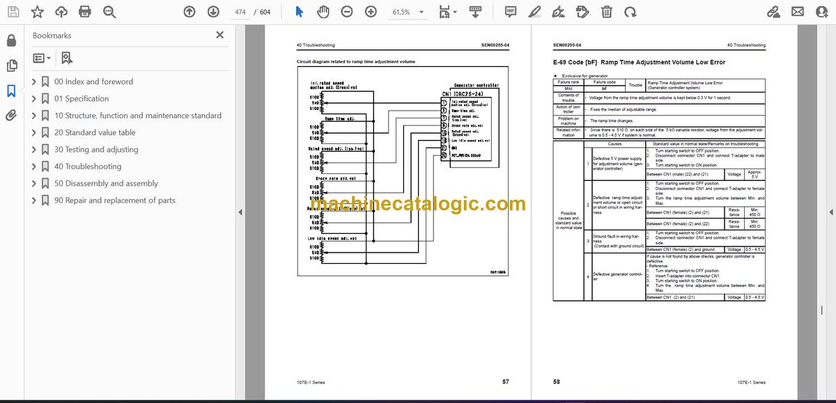
- E-69 Code [bF] Ramp Time Adjustment Volume Low Error
- Troubleshooting of mechanical system (S-mode)
- Method of using troubleshooting charts
- S-1 Starting performance is poor
- S-2 Engine does not start
- S-3 Engine does not pick up smoothly
- S-4 Engine stops during operations
- S-5 Engine does not rotate smoothly
- S-6 Engine lacks output (or lacks power)
- S-7 Exhaust smoke is black (incomplete combustion)
- S-8 Oil consumption is excessive (or exhaust smoke is blue)
- S-9 Oil becomes contaminated quickly
- S-10 Fuel consumption is excessive
- S-11 Oil is in coolant (or coolant spurts back or coolant level goes down)
- S-12 Oil pressure drops
- S-13 Oil level rises (Entry of coolant or fuel)
- S-14 Coolant temperature becomes too high (overheating)
- S-15 Abnormal noise is made
- S-16 Vibration is excessive
- 50 Disassembly and assembly
- General information on disassembly and assembly
- Precautions Before Work
- How to read this manual
- Coating materials list
- Special tools list
- Disassembly and assembly, Part 1
- General disassembly of engine
- Disassembly and assembly, Part 2
- General assembly of engine
- 90 Repair and replacement of parts
- Information related to repair and replacement
- Parts related to cylinder head
- Repair of cylinder head
- Check of valve guide
- Replacement of valve seat insert
- Vacuum test of valve seat insert
- Grinding of valve
- Parts related to cylinder block
- Repair of cylinder block
- Repair of crankshaft
- Replacement of connecting rod bushing
Komatsu


