The Komatsu DBA127 Engine is a workhorse diesel used in mid-size construction and industrial machines where downtime costs real money. This Komatsu DBA127 Engine Shop Manual (SEN07001-05) is what shops reach for when an engine’s down hard, out of spec, or coming in for a full tear-down. People buying this are usually trying to diagnose weird noises, low power, hard starts, or they’re doing major repairs after a failure. If you’re just changing oil and filters, this is more manual than you need.
What this manual helps you do
- Trace engine performance problems using step‑by‑step diagnostic procedures and guided tests.
- Check and adjust fuel system components, governor settings, and basic timing using the methods Komatsu specifies.
- Follow the correct sequence for disassembly and reassembly of the DBA127 Engine, so you don’t crack housings or misalign rotating parts.
- Diagnose lubrication, cooling, and air‑intake faults that cause overheating, low oil pressure warnings, or repeat failures.
- Handle in‑frame and out‑of‑frame overhaul work with factory procedures, including inspection points and wear limits you’re expected to measure.
Who this is for
This is aimed at shop mechanics, field techs, and rebuilders who actually pull these engines apart and sign off on repairs. A fleet manager or operator who just wants service intervals and basic checks should look for an Operation & Maintenance style manual instead of this shop manual.
FAQ
Q: Is this a PDF I can download and search?
A: Yes, it’s a PDF you can download, search by keyword, and print selected pages for use in the shop.
Q: Does this go deep enough for a full rebuild?
A: The Komatsu DBA127 Engine Shop Manual walks through diagnostic procedures, disassembly sequences, and reference torque tables used during workshop-level repairs, so it’s meant for full rebuild work, not just light service.
Q: How do I know if it matches my exact DBA127 variant?
A: You’ll want to match your machine’s engine tag to the DBA127 designation and the SEN07001-05 reference; if your plate or paperwork lists a different engine family, this isn’t the right book.
If you’re tearing into a Komatsu DBA127 Engine beyond basic filters and belts, this is the right manual; if you only handle routine maintenance, you should keep looking for a simpler operation/maintenance book.
📘 Show Index
Table of Contents:
- 00 Index and Foreword
- Index
- Foreword, Safety, Basic Information
- How to Read the Engine Shop Manual
- Safety Notice for Operation
- Precautions to Prevent Fire
- Procedures If Fire Occurs
- Precautions for Disposing of Waste Materials
- Engine Technology to Conform Exhaust Gas Emission
- Precautions for DEF
- General Character and Precautions for Handling
- Precautions for Adding
- Precautions for Storage
- Precautions for Fire Hazard and Leakage
- Other Precautions
- Store DEF
- Precautions When You Handle Hydraulic Equipment
- Precautions When You Disconnect and Connect Pipings
- Precautions When You Handle Electrical Equipment
- Precautions When You Handle Fuel System Equipment
- Precautions When You Handle Intake System Equipment
- Disconnect and Connect Push-Pull Type Coupler
- How to Disconnect and Connect Type 1 Push-Pull Type Coupler
- How to Disconnect and Connect Type 2 Push-Pull Type Coupler
- How to Disconnect and Connect Type 3 Push-Pull Type Coupler
- Precautions for Disconnection and Connection of Connectors
- How to Disconnect and Connect Deutsch Connector
- How to Disconnect and Connect Slide Lock Type Connector
- How to Disconnect and Connect Connector with Lock to Pull
- How to Disconnect and Connect Connector with Lock to Push
- How to Disconnect and Connect Connector with Housing to Rotate
- How to Read the Codes for Electric Cable
- Explanation of Terms for Maintenance Standard
- Standard Tightening Torque Table
- Conversion Table
- Abbreviation List
- 01 Specifications
- Table of Contents
- Specifications
- Outline of Exhaust Gas Regulation
- System Diagram of Engine (1-Stage Turbocharger Specification)
- System Diagram of Engine (2-Stage Turbocharger Specification)
- List of Applicable Machines: DBA127
- Specifications
- Specifications:DBA127 (D175AX-10)
- Specifications: DBA127 (HM460-6)
- Specifications: DBA127 (WA475-11, WA475-11E0)
- Specifications: DBA127 (WA485-11, WA485-11E0)
- Engine General View
- Engine General View:DBA127(D175AX-10)
- Engine General View:DBA127(HM460-6)
- Engine General View: DBA127 (WA475-11, WA475-11E0, WA485-11, WA485-11E0)
- Weight Table
- Engine Performance Curve
- Engine Performance Curve: DBA127(D175AX-10)
- Engine Performance Curve: DBA127 (HM460-6)
- Engine Performance Curve: DBA127 (WA475-11, WA475-11E0)
- Engine Performance Curve: DBA127 (WA485-11, WA485-11E0)
- 10 Structure and Function
- Table of Contents
- Engine System
- Layout of Engine Components
- Layout Drawing of Urea SCR System
- Layout Drawing of Engine Components
- Intake and Exhaust System Parts
- Layout Drawing of Intake and Exhaust System (1-Stage Turbocharger Specification)
- Intake and Exhaust System Circuit Diagram (1-Stage Turbocharger Specification)
- Function of Intake and Exhaust System (1-Stage Turbocharger Specification)
- Layout Drawing of Intake and Exhaust System (2-Stage Turbocharger Specification)
- Intake and Exhaust System Circuit Diagram (2-Stage Turbocharger Specification)
- Function of Intake and Exhaust System (2-Stage Turbocharger Specification)
- Air Cleaner
- Intake Air Heater
- Turbocharger
- Oil Mist Separator
- Exhaust Throttle Valve
- Turbo Bypass Valve
- KDPF Assembly
- DEF Mixing Device
- SCR Assembly
- Urea SCR System
- Types of Regeneration Function
- Engine Main Body Parts
- Cylinder Head
- Cylinder Block
- Main Drive Parts
- Vibration Damper
- Timing Gear
- Front Cover
- Valve System
- Flywheel and Flywheel Housing
- Lubrication System
- Layout Drawing of Lubrication System Parts
- Lubrication System Circuit Diagram
- Engine Oil Pump
- Engine Oil Filter
- Engine Oil Cooler
- Oil Cooler Thermo Valve
- Engine Oil Pan
- Fuel System
- Layout Drawing of Fuel System Parts
- Fuel System Circuit Diagram
- CRI System
- Fuel Dosing System
- Supply Pump
- Common Rail
- Injector
- Fuel Prefilter
- Fuel Main Filter
- Cooling System
- Layout Drawing of Cooling System Parts
- Cooling System Circuit Diagram
- Drive Pulley
- Water Pump
- Thermostat
- Electrical System
- Component Parts of Electrical System
- Alternator
- Starting Motor
- Engine Wiring Harness
- Engine Controller
- Fuel Feed Pump
- Fuel Feed Pump Switch
- Sensor
- Layout Drawing of Engine Sensor (1-Stage Turbocharger Specification)
- Layout Drawing of Engine Sensor (2-Stage Turbocharger Specification)
- Structure of Intake Manifold Pressure and Temperature Sensor
- Function of Intake Manifold Pressure and Temperature Sensor
- Structure of Ambient Pressure Sensor
- Function of Ambient Pressure Sensor
- Structure of Engine Oil Pressure Sensor
- Function of Engine Oil Pressure Sensor
- Structure of Charge Pressure Sensor
- Function of Charge Pressure Sensor
- Structure of Charge Temperature Sensor
- Function of Charge Temperature Sensor
- Structure of Coolant Temperature Sensor
- Function of Coolant Temperature Sensor
- Structure of NE (Crankshaft) Speed Sensor
- Function of NE (Crankshaft) Speed Sensor
- Structure of Bkup (Camshaft) Speed Sensor
- Function of Bkup (Camshaft) Speed Sensor
- Structure of Common Rail Pressure Sensor
- Function of Common Rail Pressure Sensor
- Structure of Turbocharger Speed Sensor
- Function of Turbocharger Speed Sensor
- Structure of Dosing Fuel Pressure Sensor
- Function of Dosing Fuel Pressure Sensor
- Structure of KDPF Differential Pressure and Outlet Pressure Sensor
- Function of KDPF Differential Pressure and Outlet Pressure Sensor
- Structure of Blowby Pressure Sensor
- Function of Blowby Pressure Sensor
- Structure of Engine Oil Level Sensor
- Function of Engine Oil Level Sensor
- Structure of Engine Oil Temperature Sensor
- Function of Engine Oil Temperature Sensor
- Structure of Fuel Temperature Sensor
- Function of Fuel Temperature Sensor
- Structure of Oil Mist Separator Sensor
- Function of Oil Mist Separator Sensor
- Structure of Exhaust Throttle Valve (with Built-in Position Sensor)
- Function of Exhaust Throttle Valve (with Built-in Position Sensor)
- Structure of Turbo Bypass Valve Sensor
- Function of Turbo Bypass Valve Sensor
- 20 Standard Value Table
- Table of Contents
- Standard Value Table for Engine
- Standard Value Table for Engine: DBA127(D175AX-10)
- Standard Value Table for Engine: DBA127 (HM460-6)
- Standard Value Table for Engine: DBA127 (WA475-11, WA475-11E0, WA485-11, WA485-11E0)
- Running-in Standard and Performance Test Standard
- Running-in Standard and Performance Test Standard: DBA127 (D175AX-10)
- Running-in Standard and Performance Test Standard: DBA127 (HM460-6)
- Running-in Standard and Performance Test Standard: DBA127 (WA475-11, WA475-11E0)
- Running-in Standard and Performance Test Standard: DBA127 (WA485-11, WA485-11E0)
- 50 Disassembly and Assembly
- Table of Contents
- Precautions Before Work
- Related Information on Disassembly and Assembly
- How to Read This Manual
- Coating Materials List
- Special Tool List
- Sketches of Special Tools
- Engine System
- Disassemble Engine Generally
- Preparation
- How to Remove Fuel Main Filter and Engine Oil Filter
- How to Remove Heat Insulation Cover and Protective Cover
- How to Remove Heat Insulation Cover and Protective Cover (2-Stage Turbocharger Specification)
- How to Remove Turbo Air Intake Connector
- How to Remove Turbocharger Air Supply Connector (2-Stage Turbocharger Specification)
- How to Remove Engine Wiring Harness and Engine Controller
- How to Remove Engine Wiring Harness and Engine Controller (2-Stage Turbocharger Specification)
- How to Remove Breather Tube and Oil Mist Separator
- How to Remove Breather Tube and Oil Mist Separator (2-Stage Turbocharger Specification)
- How to Remove Oil Filter Head and Oil Filler Tube
- How to Remove Oil Filter Head and Oil Filler Tube (2-Stage Turbocharger Specification)
- How to Remove Cylinder Head Cover
- How to Remove Low Pressure Fuel Piping
- How to Remove Low Pressure Fuel Piping (2-Stage Turbocharger Specification)
- How to Remove Common Rail, High-Pressure Pipe, and Injection Pipe
- How to Remove V-Belt, Alternator, Idler Pulley, and Auto-Tensioner
- How to Remove V-Belt, Alternator, Idler Pulley, and Auto-Tensioner (2-Stage Turbocharger Specification)
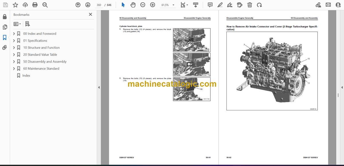
- How to Remove Air Intake Connector and Cover
- How to Remove Air Intake Connector and Cover (2-Stage Turbocharger Specification)
- How to Remove Air Conditioner Compressor
- How to Remove Front Hanger
- How to Remove Front Hanger (2-Stage Turbocharger Specification)
- How to Remove Rear Hanger
- How to Remove Rear Hanger (2-Stage Turbocharger Specification)
- How to Remove Exhaust Throttle Valve, Turbocharger, and Exhaust Manifold
- How to Remove Exhaust Throttle Valve, Turbocharger, and Exhaust Manifold (2-Stage Turbocharger Specification)
- How to Remove Starting Motor
- How to Remove Thermostat
- How to Remove Thermostat (2-Stage Turbocharger Specification)
- How to Remove Rocker Housing
- How to Remove Injector Assembly
- How to Remove Rocker Arm, Camshaft, and Cam Idler Gear
- How to Remove Cylinder Head
- How to Remove Oil Cooler
- How to Remove Front Support, and Damper and Pulley Assembly
- How to Remove Oil Level Gauge, Engine Oil Pan, Suction Tube, and Stiffener Plate
- How to Remove Oil Level Gauge, Engine Oil Pan, Suction Tube, and Stiffener Plate (2-Stage Turbocharger Specification)
- How to Remove Flywheel
- How to Remove Flywheel (2-Stage Turbocharger Specification)
- How to Remove Engine Rear Oil Seal
- How to Remove Flywheel Housing
- How to Remove Water Pump
- How to Remove Front Cover and Engine Front Oil Seal
- How to Remove Supply Pump, Timing Gear, and Engine Oil Pump
- How to Remove Piston Cooling Nozzle
- How to Remove Piston and Connecting Rod
- How to Remove Crankshaft
- How to Remove Cylinder Liner
- How to Assemble Engine Generally
- How to Install Cylinder Liner
- How to Install Crankshaft
- How to Install Piston and Connecting Rod
- How to Install Piston Cooling Nozzle
- How to Install Supply Pump, Timing Gear, and Oil Pump
- How to Install Front Cover
- How to Install Engine Front Oil Seal
- How to Install Water Pump
- How to Install Flywheel Housing
- How to Install Engine Rear Oil Seal
- How to Install Flywheel
- How to Install Flywheel (2-Stage Turbocharger Specification)
- How to Install Oil Level Gauge, Engine Oil Pan, Suction Tube, and Stiffener Plate
- How to Install Oil Level Gauge, Engine Oil Pan, Suction Tube, and Stiffener Plate (2-Stage Turbocharger Specification)
- How to Install Front Support, and Damper and Pulley Assembly
- How to Install Oil Cooler
- How to Install Cylinder Head
- How to Install Rocker Arm, Camshaft, and Cam Idler Gear
- How to Install Injector Assembly
- How to Install Rocker Housing
- How to Install Thermostat
- How to Install Thermostat (2-Stage Turbocharger Specification)
- How to Install Starting Motor
- How to Install Exhaust throttle valve, Turbocharger, and Exhaust Manifold
- How to Install Exhaust Throttle Valve, Turbocharger, and Exhaust Manifold (2-Stage Turbocharger Specification)
- How to Install Rear Hanger
- How to Install Rear Hanger (2-Stage Turbocharger Specification)
- How to Install Front Hanger
- How to Install Front Hanger (2-Stage Turbocharger Specification)
- How to Install Air Conditioner Compressor
- How to Install Air Intake Connector and Cover
- How to Install Air Intake Connector and Cover (2-Stage Turbocharger Specification)
- How to Install V-Belt, Alternator, Idler Pulley, and Auto-Tensioner
- How to Install V-Belt, Alternator, Idler Pulley, and Auto-Tensioner (2-Stage Turbocharger Specification)
- How to Install Common Rail, High-Pressure Pipe, and Injection Pipe
- How to Install Low Pressure Fuel Piping
- How to Install Low Pressure Fuel Piping (2-Stage Turbocharger Specification)
- How to Install Cylinder Head Cover
- How to Install Oil Filter Head and Oil Filler Tube
- How to Install Oil Filter Head and Oil Filler Tube (2-Stage Turbocharger Specification)
- How to Install Breather Tube and Oil Mist Separator
- How to Install Breather Tube and Oil Mist Separator (2-Stage Turbocharger Specification)
- How to Install Engine Wiring Harness and Engine Controller
- How to Install Engine Wiring Harness and Engine Controller (2-Stage Turbocharger Specification)
- How to Install Turbo Air Intake Connector
- How to Install Turbocharger Air Supply Connector (2-Stage Turbocharger Specification)
- How to Install Heat Insulation Cover and Protective Cover
- How to Install Heat Insulation Cover and Protective Cover (2-Stage Turbocharger Specification)
- How to Install Fuel Main Filter and Engine Oil Filter
- 60 Maintenance Standard
- Table of Contents
- Engine System
- Intake and Exhaust System Parts
- Maintenance Standard for Turbocharger (1-Stage Turbocharger Specification)
- Maintenance Standard for Turbocharger (2-Stage Turbocharger Specification)
- Engine Main Body Parts
- Maintenance Standard for Cylinder Head
- Maintenance Standard for Cylinder Block
- Maintenance Standard for Cylinder Liner
- Maintenance Standard for Crankshaft
- Maintenance Standard for Piston
- Maintenance Standard for Connecting Rod
- Maintenance Standard for Vibration Damper
- Maintenance Standard for Timing Gear
- Maintenance Standard for Camshaft
- Maintenance Standard for Valve and Valve Guide
- Maintenance Standard for Rocker Arm
- Maintenance Standard for Flywheel (WA475-11, WA475-11E0, WA485-11, WA485-11E0)
- Maintenance Standard for Flywheel (HM460-6, D175AX-10)
- Lubrication System
- Maintenance Standard for Engine Oil Pump
- Maintenance Standard for Safety Valve of Engine Oil Filter
- Cooling System
- Maintenance Standard for Engine Oil Cooler
- Maintenance Standard for Water Pump
- Maintenance Standard for Thermostat
- Index
Komatsu


