The Komatsu 930E-4 Rigid Dump Truck is a large mining truck built for high-hour, continuous haul work where downtime is expensive. People who usually reach for the Komatsu 930E-4 Rigid Dump Truck Shop Manual (CEBM020506) are shop mechanics, field techs, and fleet managers who plan major repairs. They’re trying to shorten diagnostic time, avoid parts mis-orders, and get trucks back in the pit on schedule instead of guessing their way through a job.
What this manual helps you do
- Trace hydraulic, electrical, and mechanical faults step-by-step so you’re not swapping expensive components blindly.
- Check removal and installation sequences for major components so you can plan labor, lifting gear, and downtime properly.
- Follow inspection and adjustment procedures that keep the engine, drivetrain, and braking system inside factory limits over long service hours.
- Diagnose warning lights, fault codes, and abnormal readings using the kind of flowcharts and test points most shops expect in a factory shop manual.
- Handle overhaul-level work on key systems with the level of detail a workshop needs, not just operator-level guidance.
Who this is for
This is aimed at field techs, shop mechanics, and fleet managers who schedule and oversee workshop repairs on the 930E-4. If you only need daily checks, basic maintenance intervals, or operating instructions, you’re better off with the Operation & Maintenance manual instead of this shop manual.
FAQ
Q: Is this a searchable PDF I can print from?
A: Yes, it’s provided as a PDF you can search on-screen and print selected pages for use in the shop.
Q: Does it go deep enough for full component repairs?
A: This kind of shop manual usually covers diagnostic procedures, disassembly/assembly sequences, and reference data for workshop-level repairs on the Komatsu 930E-4 Rigid Dump Truck.
Q: How do I know if it matches my exact truck variant?
A: You’ll want to match your machine’s identification plate to the model 930E-4 and confirm the book reference CEBM020506 is listed for your truck in your Komatsu documentation or dealer system.
Bottom line: If you’re planning or executing repairs beyond basic servicing on a Komatsu 930E-4, this is the manual you want; if you’re just operating or doing light maintenance, keep looking for the O&M book instead.
📘 Show Index
Table of Contents:
- COVER
- FOREWORD
- SECTION A GENERAL INFORMATION INDEX
- SECTION A2 MAJOR COMPONENTS & SPECIFICATIONS
- MAJOR COMPONENT DESCRIPTIONS
- Truck And Engine
- Main Alternator
- AC Induction Traction Motorized Wheels
- Suspension
- Operator's Cab
- Power Steering
- Dynamic Retarding
- Brake System
- SPECIFICATIONS
- ENGINE
- AC ELECTRIC DRIVE SYSTEM
- DYNAMIC RETARDING
- BATTERY ELECTRIC SYSTEM
- SERVICE CAPACITIES
- HYDRAULIC SYSTEMS
- SERVICE BRAKES
- STEERING
- TIRES
- STANDARD DUMP BODY CAPACITIES AND DIMENSIONS
- WEIGHT DISTRIBUTION
- SECTION A3 GENERAL SAFETY AND OPERATING INSTRUCTIONS
- GENERAL SAFETY
- GENERAL
- Safety Rules
- Safety Features
- Fire Extinguisher And First Aid Kit
- Clothing And Personal Items
- Leaving The Operator’s Seat
- Mounting And Dismounting
- Fire Prevention For Fuel And Oil
- Precautions With High Temperature Fluids
- Asbestos Dust Hazard Prevention
- Prevention Of Injury By Work Equipment
- Unauthorized Modification
- Precautions When Using ROPS
- Precautions For Attachments
- Precautions For Starting The Truck
- PRECAUTIONS BEFORE OPERATION
- Safety At The Worksite
- Fire Prevention
- Ventilation In Enclosed Areas
- Preparing For Operation
- Mirrors, Windows And Lights
- In The Operator Cab (Before Starting The Engine)
- Seat Belts
- OPERATING THE TRUCK
- When Starting The Engine
- General Truck Operation
- Ensuring Good Visibility
- Traveling
- Traveling In Reverse
- Traveling On Slopes
- Operating On Snow Or Ice
- Avoid Damage To Dump Body
- Driving Near High Voltage Cables
- Working On Loose Ground
- When Dumping
- When Loading
- Parking The Truck
- Towing
- WORKING NEAR BATTERIES
- Battery Hazard Prevention
- Jump Starting With Booster Cables
- Jump Starting With Receptacles
- BEFORE PERFORMING MAINTENANCE
- Stopping The Engine Before Service
- Warning Tag
- Proper Tools
- Use of Tie-Off Anchor During Maintenance and Repair
- Tie-off anchor installation
- Securing The Dump Body
- Jack Point Locations
- Precautions for Lifting Components
- WHILE PERFORMING MAINTENANCE
- Keep The Truck Clean
- Attachments
- Working Under The Truck
- Rotating Fan And Belts
- Waste Materials
- Adding Fuel Or Oil
- Radiator Coolant Level
- Use Of Lighting
- Precautions With The Battery
- Handling High Pressure Hoses
- Precautions With High Pressure Oil
- Performing Maintenance Near High Temperature Or High Pressure
- TIRES
- Handling Tires
- Tire Maintenance
- Storing Tires After Removal
- WHEN REPAIRS ARE NECESSARY
- SPECIAL PRECAUTIONS FOR WORKING ON AC DRIVE TRUCKS
- Preliminary Procedures Before Welding or Performing Maintenance
- Engine Shutdown Procedure Before Welding or Performing Maintenance
- CAPACITOR DISCHARGE SYSTEM
- Necessary Tools
- Warnings And Cautions
- Manual DC Link Capacitor Discharge Procedure
- Failure of the Discharge System
- Manual Discharge of Capacitors
- Short Isolated Capacitor Terminals
- OPERATING INSTRUCTIONS
- PREPARING FOR OPERATION
- WALK AROUND INSPECTION
- ENGINE START-UP
- AFTER ENGINE HAS STARTED
- PRE-SHIFT BRAKE CHECK (if equipped)
- OPERATION
- Description
- Brake Test Exit Criteria
- PERFORMING THE BRAKE TESTS
- Setup
- Service Brake Test
- Parking Brake Test
- Retard System Test
- EMERGENCY STEERING SYSTEM
- Operation
- Pre-Operation Testing
- MACHINE OPERATION SAFETY PRECAUTIONS
- OPERATING ON THE HAUL ROAD
- STARTING ON A GRADE WITH A LOADED TRUCK
- PASSING
- LOADING
- Overload Speed Limit Function
- DUMPING
- Raising The Dump Body
- Lowering The Dump Body (When dumping on flat ground):
- Lowering The Dump Body (When dumping over a berm or into a crusher):
- TOWING
- SAFE PARKING PROCEDURES
- NORMAL ENGINE SHUTDOWN PROCEDURE
- SUDDEN LOSS OF ENGINE POWER
- FUEL DEPLETION
- DISABLED TRUCK DUMPING PROCEDURE
- Hookup
- Raising the Body
- Lowering the Body
- SECTION A4 WARNINGS AND CAUTIONS
- GRADE/SPEED CHART
- KEY SWITCH
- ROPS/FOPS
- BATTERIES
- CAPACITORS
- CRUSHING HAZARD
- CYLINDER PRESSURE
- FILLING THE HYDRAULIC TANK
- HYDRAULIC OIL PRESSURE
- HOT OIL SPRAY
- WHEEL MOTOR OIL LEVEL
- HOT EXHAUST
- RADIATOR
- EMERGENCY LADDER
- ACCUMULATOR DRAIN VALVES
- EMERGENCY DUMP PROCEDURE
- EMERGENCY TOWING PROCEDURE
- WELDING
- EMERGENCY SHUTDOWN
- INFORMATION DISPLAY
- WIRELESS SIGNALS
- HIGH VOLTAGE
- LIFTING INSTRUCTIONS
- PRODUCT IDENTIFICATION PLATE
- LUBRICATION CHART
- SECTION A5 TORQUE TABLES AND CONVERSION CHARTS
- EFFECT OF SPECIAL LUBRICANTS On Fasteners and Standard Torque Values
- STANDARD TIGHTENING TORQUES For Class 10.9 Capscrews & Class 10 Nuts
- STANDARD TIGHTENING TORQUES For SAE Grade 5 and Grade 8 Capscrews
- STANDARD TIGHTENING TORQUES For SAE Grade 9 Capscrews
- SECTION A7 STORAGE PROCEDURES AND IDLE MACHINE PREPARATION
- SHORT TERM IDLE PERIODS
- PREPARATION FOR STORAGE
- REMOVAL FROM STORAGE
- RECONDITIONING AN IDLE VEHICLE
- ENGINE OPERATION
- After The Engine Has Started
- ENGINE STORAGE
- Temporary Storage (30 Days Or Less)
- Extended Storage (More Than 30 Days)
- RESTORING AN ENGINE AFTER EXTENDED STORAGE
- ELECTRIC DRIVE TRUCKS
- Storing A Truck That Is Operational
- Storing A Truck That Is Not Operational
- Storing A Major Component
- Periodic Inspections
- Placing Equipment Into Service After Storage
- SECTION B STRUCTURES INDEX
- SECTION B2 STRUCTURAL COMPONENTS INDEX
- STRUCTURAL COMPONENTS
- PREPARATION
- DIAGONAL LADDER, GRILLE AND HOOD ASSEMBLY
- RH DECK AND RETARDING GRID
- LH DECK
- CENTER DECK
- SECTION B3 DUMP BODY INDEX
- DUMP BODY
- DUMP BODY
- BODY PADS
- Body Pad Shimming Procedure
- BODY GUIDE
- HOIST LIMIT SWITCH
- BODY-UP SWITCH
- BODY RETENTION SLING
- ROCK EJECTORS
- SECTION B4 FUEL TANK INDEX
- FUEL TANK
- FUEL TANK
- Removal
- Repair
- Cleaning
- Installation
- FUEL TANK VENT ASSEMBLY
- FUEL GAUGE SENDER
- QUICK FILL FUEL RECEIVERS
- SECTION C ENGINE INDEX
- SECTION C2 POWER MODULE INDEX
- POWER MODULE
- PREPARATION FOR REMOVAL
- REMOVAL
- INSTALLATION
- HOOKUP
- EXHAUST TUBE INSTALLATION
- EXHAUST BLANKET INSTALLATION
- SECTION C3 COOLING SYSTEM INDEX
- COOLING SYSTEM
- RADIATOR
- Removal
- Installation
- Filling Procedure
- REPAIRING THE RADIATOR
- Internal Inspection
- External Cleaning
- Disassembly
- Cleaning and Inspection
- Assembly
- Pressure Testing
- COOLANT SYSTEM TROUBLESHOOTING
- SECTION C4 POWER TRAIN INDEX
- POWER TRAIN
- ALTERNATOR REMOVAL
- ALTERNATOR INSTALLATION
- Measuring Procedure
- Joining the Alternator and Engine
- ENGINE
- Removal
- Service
- Installation
- SECTION C5 AIR CLEANERS INDEX
- AIR CLEANERS
- OPERATION
- SERVICING THE AIR CLEANERS
- Replacing The Filter Element
- Cleaning The Main Filter Element
- Servicing The Precleaner Section
- EVACUATOR VALVES (if equipped)
- AIR INTAKE TROUBLESHOOTING
- SECTION C7 FAN CLUTCH INDEX
- FAN CLUTCH
- REMOVAL & INSTALLATION TOOLING
- DISASSEMBLY
- CLEANING AND INSPECTION
- ASSEMBLY
- TEST PROCEDURE
- SECTION D ELECTRICAL SYSTEM (24VDC NON-PROPULSION) INDEX
- SECTION D2 24VDC ELECTRIC SUPPLY SYSTEM INDEX
- 24VDC ELECTRICAL SUPPLY SYSTEM
- ELECTRICAL SYSTEM DESCRIPTION
- BATTERIES
- Maintenance and Service
- Troubleshooting
- BATTERY SUPPLY SYSTEM
- 24VDC Battery Charging Alternator
- Batteries
- 24VDC Auxiliary Battery Receptacles
- Battery Disconnect Switches
- Isolation Diode
- Engine Start Relay
- 24VDC to 12VDC Converter
- 24VDC ELECTRIC CRANKING MOTOR SYSTEM (WITH PRELUBE)
- Operation
- Pressure Switch
- Check Valve
- Timer Solenoid
- MAINTENANCE
- Prelube System Operation Checks
- Check Valve
- Timer Solenoid
- TROUBLESHOOTING PRELUBE CRANKING MOTOR CIRCUIT
- 24VDC ELECTRIC START SYSTEM
- CRANKING MOTORS
- Operation
- Removal
- Installation
- CRANKING MOTOR TROUBLESHOOTING
- Preliminary Inspection
- No-Load Test
- Interpreting Results of Tests
- Disassembly
- Cleaning and Inspection
- Armature Servicing
- Field Coil Checks
- Field Coil Removal
- SOLENOID CHECKS
- Test
- Assembly
- Bearing Replacement:
- Motor Assembly:
- Pinion Clearance
- MAGNETIC SWITCH
- Removal
- Installation
- Coil Test
- SECTION D3 24VDC ELECTRICAL SYSTEM COMPONENTS INDEX
- 24 VDC ELECTRICAL SYSTEM COMPONENTS
- BRAKE WARNING BUZZER
- AUXILIARY CONTROL CABINET COMPONENTS
- Power Distribution Terminals
- Pulse Voltage Modulator (PMV)
- Control Power Relay
- Auto Lube Timer
- Ground Level Power Relay
- Diode Board – DB1
- Fuse Blocks
- Alarm Indicating Device (AID) System
- RELAY BOARDS
- Relay Boards RB1, RB3, RB4, RB5
- Relay Board RB6, RB7, RB8, RB9
- Relay Board Functions
- BODY-UP SWITCH
- Operation
- Adjustment
- Service
- HOIST LIMIT SWITCH
- Operation
- Adjustment
- Service
- FUSE BLOCKS AND CIRCUIT BREAKERS
- SECTION D11 KOMTRAX PLUS INDEX
- KOMTRAX PLUS
- KOMTRAX PLUS BASIC FEATURES
- Gather Data
- Convert and Record Data
- Communicate Data to Off-Board Systems
- USING KOMTRAX PLUS
- Turning KOMTRAX Plus ON
- Normal KOMTRAX Plus Operation
- Turning KOMTRAX Plus OFF
- Downloading from the KOMTRAX Plus Controller
- KOMTRAX PLUS DATA ITEMS
- Fault Codes
- Machine History
- KOMTRAX Plus History
- Snapshots
- Manual Snapshots
- Trends
- Histogram (Load Map) Data
- Haul Cycle Data
- Alarm and Snapshot Triggers
- Satellite Features
- KOMTRAX PLUS DIAGNOSTIC FEATURES
- KOMTRAX PLUS CONTROLLER
- KOMTRAX PLUS SOFTWARE
- VHMS Tool Box Installation
- VHMS Setting Tool Installation
- PDM Software Installation
- KOMTRAX PLUS INITIALIZATION PROCEDURE
- CONTROLLER SETUP PROCEDURE
- SNAPSHOT PROCEDURE
- DOWNLOAD PROCEDURE
- FTP UPLOAD PROCEDURE
- INITIALIZATION FORMS
- WHEN REPLACING A KOMTRAX PLUS CONTROLLER
- KOMTRAX PLUS CONTROLLER CHECKOUT
- Necessary Equipment
- Preliminary
- KOMTRAX Plus Controller Checkout Procedure
- ORBCOMM CONTROLLER (if equipped)
- Removal
- Installation
- Troubleshooting
- SECTION D12 INTERFACE MODULE INDEX
- INTERFACE MODULE
- INTERFACE MODULE
- SENSORS
- Temperature Sensors
- Pressure Sensors
- INTERFACE MODULE SOFTWARE
- Flashburn Program Installation
- Interface Module Application Code Installation
- Interface Module Realtime Data Monitor Software
- INTERFACE MODULE CHECKOUT
- Necessary Equipment
- Preliminary
- Check Digital Inputs To The Interface Module
- Check Analog Inputs To The Interface Module
- Check Serial Interfaces To The Interface Module
- Check Outputs From The Interface Module
- SECTION D13 INTERFACE MODULE AND KOMTRAX PLUS TROUBLESHOOTING INDEX
- KOMTRAX Plus AND INTERFACE MODULE ERROR CODES AND TROUBLESHOOTING
- GENERAL
- TROUBLESHOOTING
- Communications Networks
- Coaxial Cable
- FAULT CODES
- Fault History
- KOMTRAX Plus LED Display Fault Codes
- Chassis Fault Codes
- Engine Fault Codes
- FAULT TREE ANALYSIS
- Unable to connect to KOMTRAX Plus from laptop PC
- Flashing Error Code N4-23 (PLM Communications Fault)
- Flashing Error Code N4-22 (Engine Communications Fault)
- No Data Received By WebCARE
- Coaxial Cable Troubleshooting
- SECTION E ELECTRIC PROPULSION SYSTEM INDEX
- SECTION E2 ELECTRIC PROPULSION SYSTEM COMPONENTS INDEX
- ELECTRICAL PROPULSION SYSTEM COMPONENTS
- GENERAL SYSTEM DESCRIPTION
- SYSTEM COMPONENTS
- Propulsion System Controller (PSC)
- Truck Control Interface (TCI)
- Diagnostic Information Display (DID) Panel
- DID Panel Event Codes
- PSC SOFTWARE FUNCTIONS
- Input Processing
- State Machine
- DC Link State
- Engine Control
- ALTERNATOR FIELD CONTROL
- Desired Three-Phase Voltage
- Desired DC Link Voltage
- Self-Load
- Propel Torque Control
- Retard Torque Control
- Wheel Slide Control
- Resistor Grid Control
- Chopper Voltage Control
- EVENT DETECTION AND PROCESSING
- Power-On Tests
- Initiated Tests
- Periodic Tests
- EVENT RESTRICTIONS
- EVENT LOGGING AND STORAGE
- Event History Buffer
- Data Packs
- To Record and Save a Data Pack to a Disk
- Event Reset
- SERIAL DATA COMMUNICATIONS
- PSC – TCI Communications Processing
- PSC – PTU Communications Processing
- Inverter Communications Processing
- OUTPUT PROCESSING
- ABNORMAL CONDITIONS/OVERRIDING FUNCTIONS
- Fast Start
- Engine Shutdown/Engine Not Running
- Limp Home Mode
- PROPULSION SYSTEM COMPONENT ABBREVIATIONS & LOCATIONS
- ELECTRONIC ACCELERATOR AND RETARD PEDALS
- Removal
- Installation
- Disassembly
- Assembly
- SECTION E3 AC DRIVE SYSTEM ELECTRICAL CHECKOUT PROCEDURE INDEX
- AC DRIVE SYSTEM ELECTRICAL CHECKOUT PROCEDURE
- AC DRIVE SYSTEM MAINTENANCE
- NORMAL TRUCK SHUTDOWN PROCEDURE
- SHUTDOWN AFTER SYSTEM FAILURE
- SYSTEM CHECKOUT
- Battery and Control Circuit Checks – Battery Power OFF
- Battery and Control Circuit Checks – Battery Power ON
- Checks with Key Switch OFF
- Checks with Key Switch ON
- CPU Battery Checks
- MEMORY BACKUP BATTERY REPLACEMENT
- TCI PROGRAMMING
- PSC PROGRAMMING
- INVERTER PROGRAMMING
- CPU RESET
- PSC CHECKOUT
- PSC Digital Input Checks
- PSC Digital Output Checks
- TCI CHECKOUT
- Modular Mining Communication Port Check
- TCI Digital Input Checks
- TCI Digital Output Tests
- CALIBRATIONS
- Speedometer
- Accelerator Pedal, Retarder Pedal/Lever and RSC Dial
- ERASING EVENTS
- GATE DRIVER POWER CONVERTER TEST
- LOAD TESTING
- Preparation
- Alternator Speed Sensor Checks
- Battery Boost Check
- Brake Circuit Switch Checks
- Hoist & Steering Circuit Switch Checks
- Link Energized Checks
- Loadbox Test
- TROUBLESHOOTING
- PVM Optimum Load Curve Handshaking Troubleshooting
- Phase Module and Chopper Module Troubleshooting
- PHASE MODULE REPLACEMENT
- Phase Module Removal
- Phase Module Installation
- SECTION E5 TROUBLESHOOTING FAULT CODES (A001-A146) INDEX
- Fault Code A001: Left front suspension pressure sensor signal is high
- Fault Code A002: Left front suspension pressure sensor signal is low
- Fault Code A003: Right front suspension pressure sensor signal is high
- Fault Code A004: Right front suspension pressure sensor signal is low
- Fault Code A005: Left rear suspension pressure sensor signal is high
- Fault Code A006: Left rear suspension pressure sensor signal is low
- Fault Code A007: Right rear suspension pressure sensor signal is high
- Fault Code A008: Right rear suspension pressure sensor signal is low
- Fault Code A009: Incline sensor signal is high
- Fault Code A010: Incline sensor signal is low
- Fault Code A011: Payload meter speed sensor signal has failed
- Fault Code A013: Body up switch has failed
- Fault Code A014: Payload meter checksum computation has failed
- Fault Code A016: Payload meter write to flash memory has failed
- Fault Code A017: Payload meter flash memory read has failed
- Fault Code A018: Right rear flat suspension cylinder warning
- Fault Code A019: Left rear flat suspension cylinder warning
- Fault Code A022: Carryback load is excessive
- Fault Code A026: Payload meter user select switch has failed
- Fault Code A027: Payload meter user clear switch has failed
- Fault Code A101: High pressure detected across a hydraulic pump filter
- Fault Code A105: Fuel level sensor is shorted to ground, indicating a false high fuel level
- Fault Code A109: GE has generated a propel system reduced level signal
- Fault Code A111: Low steering pressure warning
- Fault Code A115: Low steering precharge pressure is detected
- Fault Code A117: Low brake accumulator pressure warning
- Fault Code A118: Brake pressure is low while brake lock is activated
- Fault Code A123: GE has generated a reduced retarding caution
- Fault Code A124: GE has generated a no propel / no retard warning
- Fault Code A125: GE has generated a no propel warning
- Fault Code A126: Oil level in the hydraulic tank is low
- Fault Code A127: IM furnished +5 volt output for sensors is low
- Fault Code A128: IM furnished +5 volt output for sensors is high
- Fault Code A139, A310: Low fuel level warning
- Fault Code A145: Hydraulic temperature sensors cause advance of engine rpm to advance level 2 for cooling of hydraulic oil
- Fault Code A146: Hydraulic temperature sensors cause posting of this fault
- SECTION E5 TROUBLESHOOTING FAULT CODES (A152-A216) INDEX
- Fault Code A152: Starter failure
- Fault Code A153: Battery voltage is low with truck in operation
- Fault Code A154: Battery charging voltage is excessive
- Fault Code A155: Battery charging voltage is low
- Fault Code A158: Fuel level sensor is open or shorted high, indicating a false low fuel level
- Fault Code A166: Left rear hydraulic oil temperature sensor is low
- Fault Code A167: Right rear hydraulic oil temperature sensor is low
- Fault Code A168: Left front hydraulic oil temperature sensor is low
- Fault Code A169: Right front hydraulic oil temperature sensor is low
- Fault Code A170: Left rear hydraulic oil temperature sensor is high
- Fault Code A171: Right rear hydraulic oil temperature sensor is high
- Fault Code A172: Left front hydraulic oil temperature sensor is high
- Fault Code A173: Right front hydraulic oil temperature sensor is high
- Fault Code A184: J1939 data link is not connected
- Fault Code A190: Auto lube control has detected an incomplete lube cycle
- Fault Code A194: Left front hydraulic oil temperature is high
- Fault Code A195: Right front hydraulic oil temperature is high
- Fault Code A196: Left rear hydraulic oil temperature is high
- Fault Code A197: Right rear hydraulic oil temperature is high
- Fault Code A198: Hoist pressure 1 sensor is high
- Fault Code A199: Hoist pressure 2 sensor is high
- Fault Code A200: Steering pressure sensor is high
- Fault Code A201: Brake pressure sensor is high
- Fault Code A202: Hoist pressure 1 sensor is low
- Fault Code A203: Hoist pressure 2 sensor is low
- Fault Code A204: Steering pressure sensor is low
- Fault Code A205: Brake pressure sensor is low
- Fault Code A206: Ambient temperature sensor is high
- Fault Code A207: Ambient temperature sensor is low
- Fault Code A212: Bad truck speed signal
- Fault Code A213: Parking brake should have applied but is detected as not having applied
- Fault Code A214: Parking brake should have released but is detected as not having released
- Fault Code A215: Brake auto apply relay circuit is defective
- Fault Code A216: An open or short to ground has been detected in the parking brake command valve circuit
- SECTION E5 TROUBLESHOOTING FAULT CODES (A223-A292) INDEX
- Fault Code A223: Excessive engine cranking has occurred or a jump start has been attempted
- Fault Code A230: Parking brake has been requested while truck still moving
- Fault Code A231: Dump body is up while traveling or intending to travel
- Fault Code A233: Drive system CAN/RPC Control Link not connected
- Fault Code A235: Steering accumulator is in the process of being bled down
- Fault Code A236: Steering accumulator has not properly bled down after 90 seconds
- Fault Code A237: The CAN/RPC connection to the display is open
- Fault Code A240: The keyswitch input to the interface module is open
- Fault Code A246: Payload meter reports truck overload
- Fault Code A247: Low steering pressure warning
- Fault Code A248: The status indicator module within the display panel is defective
- Fault Code A249: Red warning lamp output used to drive the steering bleed fault lamp is shorted
- Fault Code A250: Battery voltage is low with the truck parked
- Fault Code A251: The sonalert used with the display panel (driven by IM) is open or shorted to ground.
- Fault Code A252: Start enable output circuit is either open or shorted to ground
- Fault Code A253: Steering bleed circuit is not open while running
- Fault Code A256: Red warning lamp output used to drive the steering bleed fault lamp is open
- Fault Code A257: Payload CAN/RPC is not connected
- Fault Code A258: Steering accumulator bleed pressure switch circuit is defective
- Fault Code A260: Parking brake failure
- Fault Code A261: Low brake accumulator pressure warning
- Fault Code A262: Steering bleed valve circuit open during shutdown
- Fault Code A263: Steering bleed circuit is shorted to ground
- Fault Code A264: Parking brake relay circuit is defective
- Fault Code A265: Service brake failure
- Fault Code A266: Selector lever was not in park while attempting to crank engine
- Fault Code A267: Parking brake was not set while attempting to crank engine
- Fault Code A268: Secondary engine shutdown while cranking
- Fault Code A270: Brake lock switch power supply is not on when required
- Fault Code A271: Shifter not in gear
- Fault Code A272: Brake lock switch power supply is not off when required
- Fault Code A273: A fault has been detected in the hoist or steering pump filter pressure switch circuit
- Fault Code A274: A brake setting fault has been detected
- Fault Code A275: A starter has been detected as engaged without a cranking attempt
- Fault Code A277: Parking brake applied while loading
- Fault Code A278: Service brake applied while loading
- Fault Code A279: Low steering pressure switch is defective
- Fault Code A280: Steering accumulator Bleed Down switch is defective
- Fault Code A281: Brake lock degradation switch is defective
- Fault Code A282: The number of excessive cranking counts and jump starts without the engine running has reached 7
- Fault Code A283: An engine shutdown delay was aborted because the parking brake was not set
- Fault Code A284: An engine shutdown delay was aborted because the secondary shutdown switch was operated
- Fault Code A285: The parking brake was not set when the key switch was turned off
- Fault Code A286: A fault was detected in the shutdown delay relay circuit
- Fault Code A292: The shutdown delay relay has remained on after the latched key switch circuit is off
- SECTION E5 TROUBLESHOOTING FAULT CODES (A303-A365) INDEX
- Fault Code A303: Shifter is defective
- Fault Code A304: Auto lube grease level is low
- Fault Code A306: Red warning lamp output used to drive the steering bleed fault lamp is not open when it should be
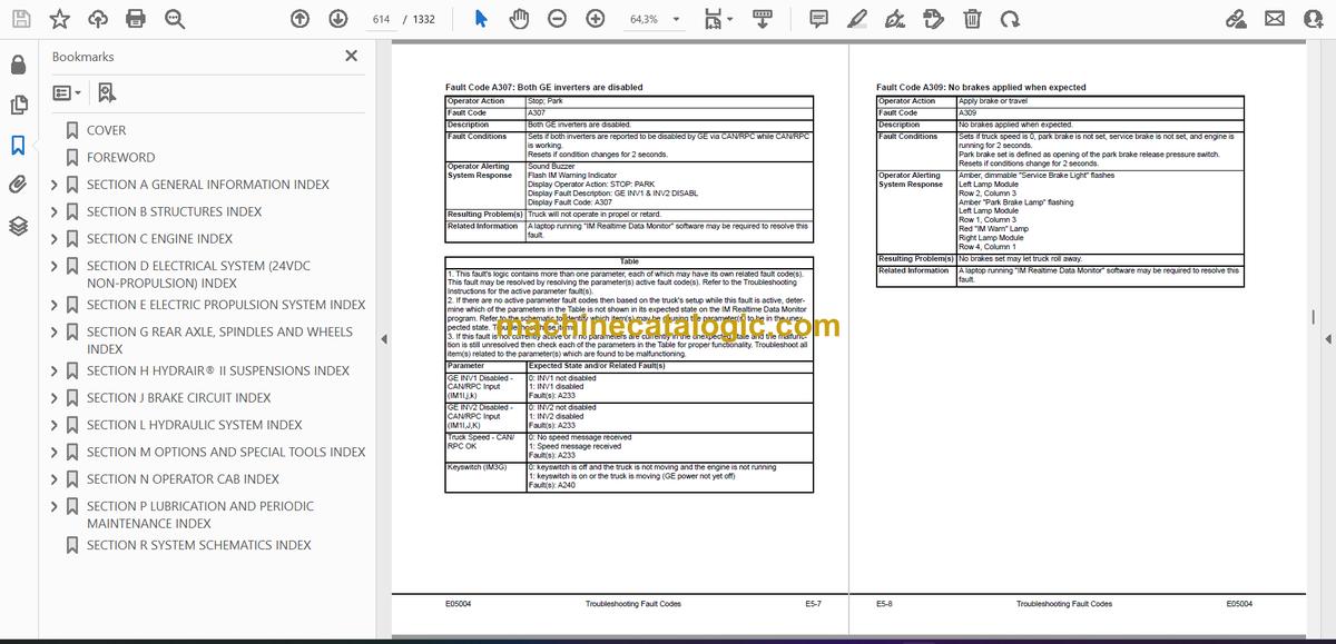
- Fault Code A307: Both GE inverters are disabled
- Fault Code A309: No brakes applied when expected
- Fault Code A311: Brake lock switch is on when it should not be
- Fault Code A312: DC-DC converter 12 volt circuit sensing is producing low readings
- Fault Code A313: DC-DC converter 12 volt circuit sensing is producing high readings
- Fault Code A315: DC-DC converter 12 volt circuit is low
- Fault Code A316: Starter engagement has been attempted with engine running
- Fault Code A317: Operation of brake auto apply valve without a detected response
- Fault Code A318: Unexpected power loss to interface module
- Fault Code A328: Drive system not powered up
- Fault Code A332: Seat belt not buckled
- Fault Code A333: The hydraulic ladder controller has declared a ladder fault
- Fault Code A334: Selector lever not in park when propel was either not ready or at rest.
- Fault Code A335: Manual/Auto Apply Pressure Fault.
- Fault Code A350: Overload on output 1B
- Fault Code A351: Overload on output 1E
- Fault Code A352: Overload on output 1H
- Fault Code A353: Overload on output 1J
- Fault Code A354: Overload on output 1K
- Fault Code A355: Overload on output 1L
- Fault Code A356: Overload on output 1M
- Fault Code A357: Overload on output 1N
- Fault Code A358: Overload on output 1P
- Fault Code A359: Overload on output 1R
- Fault Code A360: Overload on output 1S
- Fault Code A361: Overload on output 1T
- Fault Code A362: Overload on output 1U
- Fault Code A363: Overload on output 1X
- Fault Code A364: Overload on output 1Y
- Fault Code A365: Overload on output 1Z
- SECTION G REAR AXLE, SPINDLES AND WHEELS INDEX
- SECTION G2 TIRES AND RIMS INDEX
- TIRES AND RIMS
- GENERAL PRECAUTIONS
- WHEEL STUD MAINTENANCE
- WHEEL STUD INSTALLATION HEIGHT
- FRONT TIRES AND RIMS
- REAR TIRES AND RIMS
- RIM COMPONENTS
- Smart Rim Component Layout
- RIM AND TIRE SERVICE
- Lubricants
- Tire Inflation
- Lock Ring Retainer Installation
- Remove Smart Lock Ring from Inside Position of Outer Dual and Outside Position of Inner Dual
- Install Smart Lock Ring to Inside Position of Outer Dual and Outside Position of Inner Dual
- Removal (5-Piece Standard Rim)
- Removal (7-Piece Smart Rim)
- Removal (5-Piece Smart Rim)
- Preparation Before Assembly
- Installation (5-Piece Standard Rim)
- Installation – Horizontal Mount (Smart Rim)
- Installation – Vertical Mount (5-Piece Smart Rim)
- Installation – Vertical Mount (7-Piece Smart Rim)
- SECTION G3 FRONT WHEEL HUB AND SPINDLE INDEX
- FRONT WHEEL HUB AND SPINDLE
- WHEEL HUB AND SPINDLE ASSEMBLY
- Removal
- Spindle Removal Procedure (off of the truck)
- Installation
- Disassembly
- Cleaning and Inspection
- Assembly
- Wheel Bearing Adjustment
- Brake Installation
- Seal Assembly Gap Check
- WHEEL SPEED SENSOR TESTING
- STEERING CYLINDERS
- Spherical Bearing Wear Limits
- Removal
- Installation
- Bearing Replacement (Steering Cylinder and Tie Rod)
- TIE ROD
- Removal
- Installation
- Disassembly
- Assembly
- Toe-In Adjustment
- TIE ROD INSPECTION AND TORQUE PROCEDURE
- Old Style Tie Rod
- New Style Tie Rod
- SECTION G4 REAR AXLE MOUNTING INDEX
- REAR AXLE MOUNTING
- PIVOT PIN
- PIVOT EYE BEARING
- PIVOT EYE REPAIR
- Removal
- Disassembly
- Assembly
- Installation
- ANTI-SWAY BAR
- Removal
- Disassembly
- Cleaning and Inspection
- Assembly
- Installation
- SECTION G5 REAR AXLE AND WHEEL MOTOR INDEX
- REAR AXLE AND WHEEL MOTOR
- REAR AXLE HOUSING
- Preparation
- Removal
- Cleaning and Inspection
- Installation
- BLOWER PRESSURE SWITCH ADJUSTMENT
- WHEEL MOTOR
- Preparation
- Removal
- Cleaning and Inspection
- Installation
- WHEEL MOTOR GEAR OIL
- TEMPERATURE CONSTRAINTS – TRUCK OPERATION
- PROPER STORAGE AND HANDLING OF GEAR oil TO AVOID CONTAMINATION
- Filtering Requirements
- Particle Size Analysis
- Flushing
- Spectrographic Oil Sample Analysis
- ELEMENT SPECIFICATION CHARTS
- SECTION H HYDRAIR® II SUSPENSIONS INDEX
- SECTION H2 FRONT SUSPENSIONS INDEX
- FRONT SUSPENSION
- Removal
- Installation
- Inspection
- LOWER BEARING & SEALS
- MAJOR SUSPENSION REBUILD
- SUSPENSION PRESSURE TEST
- SECTION H3 REAR SUSPENSIONS INDEX
- REAR SUSPENSIONS
- SUSPENSION CYLINDER
- Removal
- Installation
- Disassembly
- Cleaning and Inspection
- Assembly
- SUSPENSION PRESSURE TEST
- SECTION H4 SUSPENSION OILING AND CHARGING PROCEDURES INDEX
- SUSPENSION OILING AND CHARGING PROCEDURES
- CHECKING FOR IMPROPER SUSPENSION CHARGE
- GENERAL
- REQUIRED EQUIPMENT
- HYDRAIR® CHARGING KIT
- Installation of Charging Kit
- Removal of Charging Kit
- SUPPORT BLOCKS FOR OILING AND CHARGING DIMENSIONS
- FRONT SUSPENSION
- REAR SUSPENSION
- OIL AND NITROGEN SPECIFICATIONS CHARTS
- SECTION J BRAKE CIRCUIT INDEX
- SECTION J2 BRAKE CIRCUIT INDEX
- BRAKE CIRCUIT
- SERVICE BRAKE CIRCUIT
- PARKING BRAKE CIRCUIT
- BRAKE LOCK CIRCUIT
- SECONDARY BRAKING AND AUTOMATIC APPLY
- WARNING CIRCUIT
- SECTION J3 BRAKE CIRCUIT COMPONENT SERVICE INDEX
- BRAKE CIRCUIT COMPONENT SERVICE
- BRAKE VALVE
- Rebuild Criteria
- Removal
- Installation
- BRAKE VALVE/PEDAL ASSEMBLY
- Disassembly
- Assembly
- Installation
- DUAL RELAY VALVE
- BRAKE MANIFOLD
- Removal
- Installation
- Disassembly
- Cleaning and Inspection
- Assembly
- BRAKE ACCUMULATORS
- Accumulator charging and storage
- Temperature during precharge
- BLADDER BRAKE ACCUMULATORS
- Brake Accumulator Bleed Down Procedure
- Removal
- Installation
- Disassembly
- Cleaning and Inspection
- Assembly
- Precharge Maintenance
- Accumulator Storage Procedures
- Installing A Bladder Accumulator From Storage
- PISTON BRAKE ACCUMULATORS
- Brake Accumulator bleed down Procedure
- Removal
- Installation
- Disassembly
- Cleaning and Inspection
- Assembly
- Piston accumulator charging procedure
- Testing
- RETARDER CONTROL LEVER (STEERING COLUMN-MOUNTED)
- Removal
- Installation
- Disassembly
- Lever Adjustments
- Potentiometer Check
- Assembly
- FRONT BRAKE COOLING HOSE INSTALLATION
- SECTION J4 BRAKE CIRCUIT CHECK-OUT PROCEDURE INDEX
- BRAKE CIRCUIT CHECK-OUT PROCEDURE
- REQUIRED EQUIPMENT
- INITIAL SYSTEM SETUP
- BRAKE LOCK / SECONDARY BRAKE CHECK-OUT
- PARKING BRAKE CHECK-OUT
- SERVICE BRAKE CHECK-OUT
- LOW ACCUMULATOR PRESSURE AND AUTO APPLY CHECK-OUT
- BRAKE CIRCUIT AND BRAKE VALVE TROUBLESHOOTING CHART
- HYDRAULIC BRAKE SYSTEM CHECK-OUT PROCEDURE DATA SHEET
- HYDRAULIC BRAKE SYSTEM CHECK-OUT PROCEDURE DATA SHEET
- SECTION J5 WET DISC BRAKE ASSEMBLY INDEX
- WET DISC BRAKE ASSEMBLY
- OPERATION
- BRAKE DISC WEAR INSPECTION
- BRAKE REBUILD
- Disassembly
- Cleaning and Inspection
- Assembly
- Brake floating ring seal assembly and installation
- Brake Floating Seal Assembly and Installation
- WET DISC BRAKE BLEEDING PROCEDURE
- SECTION J7 PARKING BRAKE INDEX
- PARKING BRAKE
- OPERATION
- MAINTENANCE
- Inspection
- Removal
- Installation
- Disassembly
- Cleaning and Inspection
- Assembly
- Cleaning and Inspecting New Discs
- PARKING BRAKE BLEEDING PROCEDURE
- SECTION L HYDRAULIC SYSTEM INDEX
- SECTION L2 HYDRAULIC SYSTEM INDEX
- HYDRAULIC SYSTEM
- HYDRAULIC PUMP MODULE
- HOIST CIRCUIT OPERATION
- STEERING CIRCUIT OPERATION
- DISC BRAKE COOLING SYSTEM
- SECTION L3 HYDRAULIC SYSTEM COMPONENT REPAIR INDEX
- HYDRAULIC SYSTEM COMPONENT REPAIR
- HOIST PUMP
- Removal
- Installation
- Inspection
- Assembly
- HYDRAULIC TANK
- HYDRAULIC TANK BREATHERS
- HYDRAULIC TANK STRAINERS
- Removal
- Inspect and Clean
- Installation
- SECTION L4 STEERING CIRCUIT INDEX
- STEERING CIRCUIT
- STEERING CIRCUIT OPERATION
- COMPONENT DESCRIPTION
- Steering Control Unit
- Bleed Down Manifold
- Steering Accumulator Bleed Down Solenoid
- Relief Valves
- Hoist Up Limit Solenoid
- Steering Accumulators
- Low Precharge Warning Switch
- High Pressure Filter
- Quick Disconnect Ports
- Flow Amplifier
- FLOW AMPLIFIER SYSTEM OPERATION
- No Steer
- Steering Left
- Steering Right
- No Steer, External Shock Load
- STEERING PUMP
- Normal Operation
- High Altitude Operation
- PRINCIPLE OF OPERATION
- Full Pump Volume
- Half Pump Volume
- Neutral Position
- Steering Pump
- SECTION L5 STEERING CONTROL UNIT INDEX
- STEERING CONTROL UNIT
- REMOVAL
- SPLINE INSPECTION
- INSTALLATION
- DISASSEMBLY
- CLEANING AND INSPECTION
- ASSEMBLY
- SECTION L6 STEERING CIRCUIT COMPONENT REPAIR INDEX
- STEERING CIRCUIT COMPONENT REPAIR
- BLEEDDOWN MANIFOLD VALVE
- FLOW AMPLIFIER
- Removal
- Installation
- Disassembly
- Assembly
- STEERING CYLINDERS
- Disassembly
- Piston Seal & Bearing Installation
- Assembly
- Testing
- STEERING AND BRAKE PUMP
- Removal
- Installation
- Disassembly
- Inspection
- Assembly
- Driveshaft Group
- Rotating Group
- Valve Plate Group
- STEERING ACCUMULATORS
- Removal
- Installation
- Disassembly
- Cleaning and Inspection
- Assembly
- Leak Testing
- Charging Procedure
- Precharge Maintenance
- Accumulator Storage Procedures
- Bladder Storage Procedures
- Installing A Bladder Accumulator From Storage
- TROUBLESHOOTING CHART
- SECTION L7 HOIST CIRCUIT INDEX
- HOIST CIRCUIT
- BASIC OPERATION
- COMPONENT DESCRIPTION
- Hydraulic Tank
- Hydraulic Pump
- High Pressure Filters
- Hoist Valve
- Inlet Sections
- Work Ports (Rear) Spool Section
- Tank Ports (Front) Spool Section
- Hoist Pilot Valve
- Bleeddown Manifold
- Hoist Up Limit Solenoid
- Pilot Operated Check Valve
- Overcenter Manifold
- HOIST CIRCUIT OPERATION
- Float Position Of Pilot Valve With Truck Body On Frame
- Power Up Operation
- Hold Operation
- Power Down Operation
- Float Operation
- SECTION L8 HOIST CIRCUIT COMPONENT REPAIR INDEX
- HOIST CIRCUIT COMPONENT REPAIR
- HOIST VALVE
- Removal
- Installation
- O-Ring Replacement
- INLET SECTION
- Cleaning and Inspection
- Assembly
- REAR SPOOL SECTION (Work Ports)
- Disassembly
- Cleaning and Inspection
- Assembly
- FRONT SPOOL SECTION (Tank Ports)
- Disassembly
- Cleaning and Inspection
- Assembly
- HOIST PILOT VALVE
- Removal
- Installation
- Disassembly
- Cleaning and Inspection
- Assembly
- HOIST CYLINDERS
- Removal
- Installation
- Disassembly
- Cleaning and Inspection
- Assembly – Quill
- Assembly – Cylinder
- Testing
- OVERCENTER VALVE MANIFOLD
- SECTION L9 HYDRAULIC SYSTEM FILTERS INDEX
- HYDRAULIC SYSTEM FILTERS
- HOIST CIRCUIT FILTER
- Filter Element Replacement
- Removal – Hoist Circuit Filter
- Installation – Hoist Circuit Filter
- Indicator Switch – Hoist Circuit Filter
- STEERING CIRCUIT FILTER
- Filter Element Replacement
- Removal – Steering Circuit Filter
- Installation – Steering Circuit Filter
- Indicator Switch – Steering Circuit Filter
- INDICATOR SWITCH
- SECTION L10 HYDRAULIC CHECKOUT PROCEDURE INDEX
- 930E CHECK-OUT PROCEDURE – BRAKE COOLING & HOIST SYSTEM DATA SHEET L10-22
- HYDRAULIC CHECKOUT PROCEDURE
- GENERAL INFORMATION
- STEERING CIRCUIT CHECK-OUT & ADJUSTMENT PROCEDURE
- STEERING/BRAKE PUMP STROKE ADJUSTMENT
- SHOCK AND SUCTION VALVES
- HOIST SYSTEM RELIEF VALVE AND BRAKE COOLING CIRCUIT PRESSURES
- 930E CHECK-OUT PROCEDURE – STEERING SYSTEM DATA SHEET
- 930E CHECK-OUT PROCEDURE – BRAKE COOLING & HOIST SYSTEM DATA SHEET
- SECTION M OPTIONS AND SPECIAL TOOLS INDEX
- SECTION M7 HOT START SYSTEM INDEX
- HOT START SYSTEM
- SYSTEM OPERATION
- HEATER INFORMATION
- TROUBLESHOOTING GUIDELINES
- SECTION M8 SPECIAL TOOLS
- HIGH VOLTAGE TOOLS
- 0-2000 VDC CUSTOM METER KIT (58B-06-00800)
- SECTION M19 RADIATOR SHUTTERS INDEX
- RADIATOR SHUTTERS
- OPERATION
- Hydraulic Circuit
- Electrical Circuit
- MAINTENANCE AND REPAIR
- TROUBLESHOOTING
- SECTION M20 PAYLOAD METER III ™ INDEX
- OPERATION SECTION
- Introduction
- Data Summary
- Data Gathering
- COMPONENT DESCRIPTION
- System Diagram
- Suspension Pressure Sensors
- Inclinometer
- Operator Display
- Operator Switch
- Speed Input
- Body-Up Switch
- Brake Lock Switch
- Payload Meter
- Communications Ports
- Key Switch Input
- Payload Meter Power
- Load Lights
- Wiring and Termination
- TCI Outputs
- OPERATOR’S DISPLAY AND SWITCH
- Reading the Speedometer/Digital Display
- Reading the Load Display
- Using the Operator ID
- Using the Load and Ton Counter
- Total Ton Counter
- Total Load Counter
- Clearing the Counters
- Viewing Live Sensor Data
- Other Display Messages
- PAYLOAD OPERATION & CALCULATION
- Description of Haul Cycle States
- Haul Cycle Description
- Load Calculation
- Carry Back
- Measurement Accuracy
- SOURCES FOR PAYLOAD ERROR
- Payload Error
- Loading Conditions
- Pressure Sensors
- Swingloads
- Speed and Distance
- HAUL CYCLE DATA
- Haul Cycle Warning Flags
- Frame Torque Data
- Sprung Weight Data
- Maximum Speed Data
- Alarm Records
- Fault Code Data
- PC SOFTWARE OVERVIEW
- System Configuration
- Installing the PLMIII Software
- DOWNLOADING DATA
- PLM III SYSTEM CONFIGURATION
- Starting Communications
- Displayed Payload Units
- Time Units
- Connection Menu
- Connecting to the Payload Meter
- Configure the Payload Meter
- Setting the Date and Time
- Setting the Truck Type
- Setting the Gauge Display Units
- Setting the Frame Serial Number
- Setting the Truck Number
- Setting the Komatsu Distributor
- Setting the Komatsu Customer
- Clean Truck Tare Calibration
- Inclinometer Calibration
- DATA ANALYSIS
- Creating a Query
- Sorting on Truck Unit Number
- Sorting on Truck Type
- Sorting on Date Range
- Sorting on Time Range
- Payload Detail Screen
- Creating Reports
- Summary – one page report
- Detailed – multi-page report
- Creating Graphs
- Exporting Data
- CSV Export
- Compressed
- Importing Data
- Deleting Haul Cycle Records
- Viewing Alarms
- Deleting Alarm Records
- TROUBLESHOOTING SECTION
- TROUBLESHOOTING
- Viewing Active Alarms
- Real-Time Data Display
- Testing the Payload Lights
- Creating Log Files of Inputs
- Daily Inspections
- Periodic Maintenance
- Abnormal Displays at Power-Up
- No Payload Display When Key Switch is Turned ON
- No Display on Speedometer
- No Display on Operator Display
- No Communications With PC
- Load Lights Don’t Light During Loading
- Load Lights Remain ON
- Load Lights Remain ON During Dumping
- Display Doesn't Clear When The Load Is Dumped
- Calibration Problems
- Alarm 1 – Left Front Pressure High
- Alarm 2 – Left Front Pressure Low
- Troubleshoot Wiring to Left Front Suspension
- Alarm 3 – Right Front Pressure High
- Alarm 4 – Right Front Pressure Low
- Troubleshoot Wiring to Right Front Suspension
- Alarm 5 -Left Rear Pressure High
- Alarm 6 – Left Rear Pressure Low
- Troubleshoot Wiring to Left Rear Suspension
- Alarm 7 – Right Rear Pressure High
- Alarm 8 – Right Rear Pressure Low
- Troubleshoot Wiring to Right Rear Suspension
- Alarm 9 – Inclinometer High
- Alarm 10 – Inclinometer Low
- Troubleshoot Inclinometer Wiring
- Alarm 13 – Body Up Input Failure
- Alarm 16 – Memory Write Failure
- Alarm 17 – Memory Read Failure
- Alarm 18
- Alarm 19
- Alarm 22
- Operator Switch Doesn't Work
- Alarm 26 – User Switch Fault – SELECT
- Alarm 27 – User Switch Fault – SET
- Connector Map
- Connectors
- PLMIII CHECK OUT PROCEDURE
- General Description
- Tools Required
- Checkout Procedure
- PLMIII CHECKOUT PROCEDURE CONFIRMATION
- Flashburn Programming
- Confirmation Checklist
- SECTION M31 RESERVE ENGINE OIL SYSTEM INDEX
- RESERVE ENGINE OIL SYSTEM
- Operation
- LED Monitor Light
- Tank Fill Control (Optional)
- Filling Procedure (Remote Fill Feature)
- SERVICE
- Every 10 Hours, or once each shift:
- Every 500 Hours
- Changing Oil
- TROUBLESHOOTING
- SYSTEM ELECTRICAL SCHEMATICS
- SECTION N OPERATOR CAB INDEX
- SECTION N2 TRUCK CAB AND COMPONENTS INDEX
- TRUCK CAB AND COMPONENTS
- TRUCK CAB
- Description
- Removal
- Installation
- CAB DOOR
- Removal
- Installation
- Door Jamb Bolt Adjustment
- Door Handle Plunger Adjustment
- Replacing the Door Glass
- Replacing the Door Handle or Latch Assembly
- Replacing the Door Window Regulator
- Replacing the Door and Door Hinge Seal
- Replacing the Door Opening Seal
- GLASS REPLACEMENT (Adhesive-Bonded Windows)
- Recommended Tools and Supplies
- Replacement Procedure
- WINDSHIELD AND REAR GLASS
- SECTION N3 CAB COMPONENTS INDEX
- CAB COMPONENTS
- WINDSHIELD WIPERS
- WIPER MOTOR
- WIPER ARM
- WIPER LINKAGE
- WINDSHIELD WASHER
- OPERATOR SEAT
- Seat Belts
- Adjustment
- Inspection
- Removal
- Installation
- PASSENGER SEAT
- Inspection
- Removal
- Installation
- SECTION N4 HEATER / AIR CONDITIONER INDEX
- HEATER/AIR CONDITIONER
- OPERATION
- Fan Speed Control Knob
- Temperature Control Knob
- Air Flow Directional Knob
- Heater/Air Conditioner Vents
- COMPONENTS
- Fuse and Circuit Breaker
- Relays
- Heater Core
- Fan Motor And Speed Control
- Actuators
- Cab Air Filter
- ENVIRONMENTAL IMPACT OF AIR CONDITIONING
- AIR CONDITIONING FOR OFF-HIGHWAY VEHICLES
- PRINCIPLES OF REFRIGERATION
- Air Conditioning
- Refrigeration – The Act Of Cooling
- The Refrigeration Cycle
- AIR CONDITIONER SYSTEM COMPONENTS
- Compressor (Refrigerant Pump)
- Service Valves
- Condenser
- Receiver-Drier
- Expansion Block Valve
- Accumulator
- Evaporator
- ELECTRICAL CIRCUIT
- Thermostat
- Compressor Clutch
- Trinary™ Switch
- AIR CONDITIONING SYSTEM SERVICING WARNINGS
- SERVICE TOOLS AND EQUIPMENT
- Recovery/Recycle Station
- Leak Detector
- Manifold Gauge Set
- Installing Manifold Gauge Set
- Purging Air From Service Hoses
- Service Valves
- Vacuum Pump
- SYSTEM PERFORMANCE TEST
- SYSTEM OIL
- Handling and Reusing PAG Oil
- Oil Quantity
- Checking System Oil
- REFRIGERANT
- Recycled Refrigerant
- Reclaimed Refrigerant
- Refrigerant Quantity
- R-134a Refrigerant Containers
- SYSTEM LEAK TESTING
- Electronic Leak Detector
- Tracer Dyes
- Soap and Water
- RECOVERING AND RECYCLING THE REFRIGERANT
- Draining Oil from the Previous Recovery Cycle
- Performing the Recovery Cycle
- Performing the Recycling Procedure
- Evacuating and Charging the A/C System
- SYSTEM REPAIR
- A/C DRIVE BELT CHECKOUT PROCEDURE
- Pulley Alignment
- Belt Tension Check
- COMPONENT REPLACEMENT
- Hoses and Fittings
- Lines
- Expansion Valve
- Receiver-Drier
- Thermostat
- Compressor
- Accumulator
- Clutch
- Servicing the Compressor Clutch
- Pulley Removal
- Clutch Coil Check
- Pulley Installation
- Clutch Assembly Installation
- EVACUATING THE SYSTEM
- CHARGING THE A/C SYSTEM
- TROUBLESHOOTING
- Preliminary Checks
- Diagnosis Of Gauge Readings And System Performance
- TROUBLESHOOTING BY MANIFOLD GAUGE SET READINGS
- PREVENTIVE MAINTENANCE SCHEDULE FOR A/C SYSTEM
- SECTION N5 OPERATOR CAB CONTROLS INDEX
- OPERATOR CAB CONTROLS
- STEERING COLUMN
- Removal
- Inspection
- Installation
- STEERING WHEEL
- STEERING WHEEL AND CONTROLS
- Horn Button
- Tilt / Telescope Lever
- Multi-Function Turn Signal Switch
- DYNAMIC RETARDING
- Retarder Lever
- Brake/Retarder Pedal
- Throttle/Accelerator Pedal
- GRADE/SPEED CHART
- OVERHEAD PANEL AND DISPLAYS
- Speakers
- Warning Alarm Buzzer
- Radio/CD Player
- Warning Indicator Light Dimmer Control
- Status/Warning Indicator Light Panel
- Air Cleaner Restriction Gauges
- CENTER CONSOLE
- Directional Control Lever
- Override/Fault Reset Switch
- Engine Shutdown Switch
- Window Control Switches
- Hoist Control Lever
- Retarder Speed Control (RSC) Adjustment Dial
- Retarder Speed Control (RSC) Switch
- Data Store Button
- KOMTRAX Plus Snapshot In Progress Light
- Link Energized Light
- Service Engine Light
- 12V Auxiliary Power Outlets
- DIAGNOSTIC PORTS
- KOMTRAX Plus Diagnostic Port
- Interface Module (IM) Diagnostic Port
- Payload Meter Diagnostic Port
- Truck Control Interface (TCI) Diagnostic Port
- Propulsion System Controller (PSC) Diagnostic Port
- Engine Diagnostic Port (CENSE)
- Engine Diagnostic Port (QUANTUM)
- INSTRUMENT PANEL
- Control Symbols
- Key Switch
- Rotating Beacon Switch (optional)
- Heated Mirrors Switch (optional)
- AC Drive System Rest Switch
- Wheel Brake Lock Switch
- Hazard Warning Lights
- Heater/Air Conditioner Vents
- Engine Oil Pressure Gauge
- Right Turn Signal Indicator
- Digital Tachometer
- High Beam Indicator
- Speedometer/Payload Meter Display
- Left Turn Signal Indicator
- Coolant Temperature Gauge
- Lamp Check Switch
- Light Switch (3-Way)
- Ladder Light Switch
- Backup Light Switch
- Fog Light Switch
- Payload Meter Switch
- Panel Illumination Light Dimmer Switch
- Hydraulic Oil Temperature Gauge
- Engine Hourmeter
- Fuel Gauge
- OVERHEAD STATUS / WARNING INDICATORS
- A1. High Hydraulic Oil Temperature
- B1. Low Steering Pressure
- C1. Low Accumulator Precharge Pressure
- D1. Not used
- E1. Low Brake Pressure
- A2. Low Hydraulic Tank Level
- B2. Low Automatic Lubrication System Pressure
- C2. Circuit Breaker Tripped
- D2. Hydraulic Oil Filter Monitor
- E2. Low Fuel
- A3. Parking Brake
- B3. Service Brake
- C3. Body Up
- D3. Dynamic Retarding
- E3. Stop Engine
- A4. Cranking Motor Failure
- B4. Backup Lights
- C4. Engine Shutdown Timer
- D4. Retard Speed Control (RSC) Indicator
- E4. Check Engine
- A5. No Power
- B5. Propulsion System Warning
- C5. Propulsion System Temperature
- D5. System/Component Failure
- E5. Battery Charging System Failure
- A6. No Propel
- B6. Propel System At Rest
- C6. Propel System Not Ready
- D6. Reduced Propulsion
- E6. Retard At Continuous Level
- REAR AXLE LIGHT BAR
- Backup Lights
- Retard Lights
- Brake Light
- Backup Alarm
- KOMTRAX PLUS
- Operation
- Interface Module
- Basic Precautions
- KOMATSU WIRELESS BRIDGE (Optional)
- General Information
- Communication Setup
- Switching to the KWB_SETUP Network
- Setting the Computer Subnet Mask and IP Address
- Properties
- Setting Up the KWB
- Adding Encryption
- Final Computer Settings
- Data Downloading
- Resetting the KWB
- KWB Lights
- SECTION P LUBRICATION AND PERIODIC MAINTENANCE INDEX
- SECTION P2 LUBRICATION AND SERVICE INDEX
- LUBRICATION AND SERVICE
- GENERAL
- SERVICE CAPACITIES
- HYDRAULIC TANK SERVICE
- COOLING SYSTEM SERVICE
- Radiator Filling Procedure
- Coolant Specifications
- Unacceptable Practices
- WHEEL MOTOR SERVICE
- RESERVE OIL TANK SERVICE
- Filling the Reserve Oil Tank (Remote Fill)
- Inline Screen
- QUICK FILL SERVICE CENTER
- LUBRICATION CHART
- 10 HOUR (DAILY) INSPECTIONS
- 50 HOUR LUBRICATION AND MAINTENANCE CHECKS
- 100 HOUR LUBRICATION AND MAINTENANCE CHECKS
- 250 HOUR LUBRICATION AND MAINTENANCE CHECKS
- 500 HOUR LUBRICATION AND MAINTENANCE CHECKS
- 1000 HOUR LUBRICATION AND MAINTENANCE CHECKS
- 5000 HOUR MAINTENANCE CHECKS
- SECTION P3 AUTOMATIC LUBRICATION SYSTEM INDEX
- AUTOMATIC LUBRICATION SYSTEM
- GENERAL DESCRIPTION
- SYSTEM COMPONENTS
- Filter
- Hydraulic Motor and Pump
- Grease Reservoir
- Pressure Reducing Valve
- Flow Control Valve
- Solenoid Valve
- Vent Valve
- Lubrication Cycle Timer
- Over Pressure Cut Off Switch
- Grease Pressure Failure Switch
- Injectors
- Relief Valve (unloader valve)
- SYSTEM OPERATION
- Normal Operation
- Lubricant Required For System
- System Priming
- Filter Assembly
- LUBRICANT PUMP
- Pump Housing Oil Level
- Pump Pressure Control
- INJECTORS (SL-1 Series “H”)
- Injector Specifications
- Injector Adjustment
- INJECTOR OPERATION
- PREVENTIVE MAINTENANCE PROCEDURES
- Daily Lubrication System Inspection
- 250 Hour Inspection
- 1000 Hour Inspection
- SYSTEM CHECKOUT
- Lubrication Controller Check
- Lubrication Controller Components
- Lubrication Controller Adjustment
- SYSTEM TROUBLESHOOTING CHART
- SECTION R SYSTEM SCHEMATICS INDEX
Komatsu


