The Komatsu 930E-4 Rigid Dump Truck is a mine-haul truck that spends its life moving huge loads on long haul roads, under hard braking and rough conditions. People who reach for the Komatsu 930E-4 Rigid Dump Truck Shop Manual (CEBM020207) are usually shop mechanics, field techs, or trainers trying to keep a fleet running or bring new techs up to speed. They’re not looking for sales fluff; they want the “how and why” behind teardown, testing, and putting it back together without repeat failures.
What this manual helps you do
- Trace hydraulic and electric drive faults step‑by‑step so you’re not just throwing parts at warning lights.
- Diagnose braking, retarder, and steering issues using the test procedures and expected system behaviors these manuals usually lay out.
- Follow disassembly and reassembly sequences for major components like the diesel engine, wheel groups, and suspension so students don’t skip critical order-of-operations steps.
- Check adjustment procedures for linkages, brakes, and system controls so the truck returns to service operating within design intent, not just “good enough.”
- Verify troubleshooting logic for fault codes and abnormal readings, which is where new technicians most often misinterpret symptoms.
Who this is for
This shop manual is aimed at workshop-level people: field technicians, mine-site shop mechanics, and technical trainers building lesson plans around real procedures. If you’re an operator or fleet manager just wanting daily checklists or basic maintenance intervals, you’d be better off with the operation and maintenance manual instead.
FAQ
Q: Is this a PDF I can search and print?
A: Yes, this is typically supplied as a searchable PDF that you can print sections from for use in the shop.
Q: Is it deep enough for full overhauls, or just basic service?
A: A Komatsu shop manual like CEBM020207 is written for full diagnostic work, teardown, inspection, and reassembly, not just oil changes.
Q: How do I know if it matches my exact 930E-4 truck?
A: You’ll want to match this CEBM020207 shop manual to your truck’s model designation and serial information from Komatsu or your dealer before you buy.
Bottom line: If you’re repairing or teaching others to repair the Komatsu 930E-4 Rigid Dump Truck at component level, this is more or less the right manual; if you only need operating tips or light service info, keep looking for the operation and maintenance book instead.
📘 Show Index
Table of Contents:
- COVER
- FOREWORD
- SECTION A GENERAL INFORMATION INDEX
- SECTION A2 MAJOR COMPONENTS & SPECIFICATIONS
- TRUCK AND ENGINE
- MAIN ALTERNATOR
- AC INDUCTION TRACTION MOTORIZED WHEELS
- SUSPENSION
- OPERATOR’S CAB
- POWER STEERING
- DYNAMIC RETARDING
- BRAKE SYSTEM
- ENGINE
- AC ELECTRIC DRIVE SYSTEM
- DYNAMIC RETARDING
- BATTERY ELECTRIC SYSTEM
- SERVICE CAPACITIES
- HYDRAULIC SYSTEMS
- SERVICE BRAKES
- STEERING
- TIRES
- STANDARD DUMP BODY CAPACITIES AND DIMENSIONS
- WEIGHT DISTRIBUTION
- SECTION A3 GENERAL SAFETY AND OPERATING INSTRUCTIONS
- GENERAL SAFETY
- GENERAL
- Safety Rules
- Safety Features
- Fire Extinguisher And First Aid Kit
- Clothing And Personal Items
- Leaving The Operator’s Seat
- Mounting And Dismounting
- Fire Prevention For Fuel And Oil
- Precautions With High Temperature Fluids
- Asbestos Dust Hazard Prevention
- Prevention Of Injury By Work Equipment
- Unauthorized Modification
- Precautions When Using ROPS
- Precautions For Attachments
- Precautions For Starting The Truck
- PRECAUTIONS BEFORE OPERATION
- Safety At The Worksite
- Fire Prevention
- Ventilation In Enclosed Areas
- Preparing For Operation
- Mirrors, Windows And Lights
- In The Operator Cab (Before Starting The Engine)
- Seat Belts
- OPERATING THE TRUCK
- When Starting The Engine
- General Truck Operation
- Ensuring Good Visibility
- Traveling
- Traveling In Reverse
- Traveling On Slopes
- Operating On Snow Or Ice
- Avoid Damage To Dump Body
- Driving Near High Voltage Cables
- Working On Loose Ground
- When Dumping
- When Loading
- Parking The Truck
- Towing
- WORKING NEAR BATTERIES
- Battery Hazard Prevention
- Jump Starting With Booster Cables
- Jump Starting With Receptacles
- BEFORE PERFORMING MAINTENANCE
- Stopping The Engine Before Service
- Warning Tag
- Proper Tools
- Use of Tie-Off Anchor During Maintenance and Repair
- Tie-off anchor installation
- Securing The Dump Body
- Jack Point Locations
- Precautions for Lifting Components
- WHILE PERFORMING MAINTENANCE
- Keep The Truck Clean
- Attachments
- Working Under The Truck
- Rotating Fan And Belts
- Waste Materials
- Adding Fuel Or Oil
- Radiator Coolant Level
- Use Of Lighting
- Precautions With The Battery
- Handling High Pressure Hoses
- Precautions With High Pressure Oil
- Performing Maintenance Near High Temperature Or High Pressure
- TIRES
- Handling Tires
- Tire Maintenance
- Storing Tires After Removal
- WHEN REPAIRS ARE NECESSARY
- SPECIAL PRECAUTIONS FOR WORKING ON AC DRIVE TRUCKS
- Preliminary Procedures Before Welding or Performing Maintenance
- Engine Shutdown Procedure Before Welding or Performing Maintenance
- CAPACITOR DISCHARGE SYSTEM
- Necessary Tools
- Warnings And Cautions
- Manual DC Link Capacitor Discharge Procedure
- Failure of the Discharge System
- Manual Discharge of Capacitors
- Short Isolated Capacitor Terminals
- OPERATING INSTRUCTIONS
- PREPARING FOR OPERATION
- WALK AROUND INSPECTION
- ENGINE START-UP
- AFTER ENGINE HAS STARTED
- PRE-SHIFT BRAKE CHECK (if equipped)
- OPERATION
- Description
- Brake Test Exit Criteria
- PERFORMING THE BRAKE TESTS
- Setup
- Service Brake Test
- Parking Brake Test
- Retard System Test
- EMERGENCY STEERING SYSTEM
- Operation
- Pre-Operation Testing
- MACHINE OPERATION SAFETY PRECAUTIONS
- OPERATING ON THE HAUL ROAD
- STARTING ON A GRADE WITH A LOADED TRUCK
- PASSING
- LOADING
- Overload Speed Limit Function
- DUMPING
- Raising The Dump Body
- Lowering The Dump Body (When dumping on flat ground):
- Lowering The Dump Body (When dumping over a berm or into a crusher):
- TOWING
- SAFE PARKING PROCEDURES
- NORMAL ENGINE SHUTDOWN PROCEDURE
- SUDDEN LOSS OF ENGINE POWER
- FUEL DEPLETION
- DISABLED TRUCK DUMPING PROCEDURE
- Hookup
- Raising the Body
- Lowering the Body
- SECTION A4 WARNINGS AND CAUTIONS
- GRADE/SPEED CHART
- KEY SWITCH
- ROPS/FOPS
- BATTERIES
- CAPACITORS
- CRUSHING HAZARD
- CYLINDER PRESSURE
- FILLING THE HYDRAULIC TANK
- HYDRAULIC OIL PRESSURE
- HOT OIL SPRAY
- WHEEL MOTOR OIL LEVEL
- HOT EXHAUST
- RADIATOR
- EMERGENCY LADDER
- ACCUMULATOR DRAIN VALVES
- EMERGENCY DUMP PROCEDURE
- EMERGENCY TOWING PROCEDURE
- WELDING
- EMERGENCY SHUTDOWN
- INFORMATION DISPLAY
- WIRELESS SIGNALS
- HIGH VOLTAGE
- LIFTING INSTRUCTIONS
- PRODUCT IDENTIFICATION PLATE
- LUBRICATION CHART
- SECTION A5 TORQUE TABLES AND CONVERSION CHARTS
- EFFECT OF SPECIAL LUBRICANTS On Fasteners and Standard Torque Values
- STANDARD TIGHTENING TORQUES For Class 10.9 Capscrews & Class 10 Nuts
- STANDARD TIGHTENING TORQUES For SAE Grade 5 and Grade 8 Capscrews
- STANDARD TIGHTENING TORQUES For SAE Grade 9 Capscrews
- SECTION A7 STORAGE PROCEDURES AND IDLE MACHINE PREPARATION
- SHORT TERM IDLE PERIODS
- PREPARATION FOR STORAGE
- REMOVAL FROM STORAGE
- RECONDITIONING AN IDLE VEHICLE
- ENGINE OPERATION
- After The Engine Has Started
- ENGINE STORAGE
- Temporary Storage (30 Days Or Less)
- Extended Storage (More Than 30 Days)
- RESTORING AN ENGINE AFTER EXTENDED STORAGE
- ELECTRIC DRIVE TRUCKS
- Storing A Truck That Is Operational
- Storing A Truck That Is Not Operational
- Storing A Major Component
- Periodic Inspections
- Placing Equipment Into Service After Storage
- SECTION B STRUCTURES INDEX
- SECTION B2 STRUCTURAL COMPONENTS INDEX
- STRUCTURAL COMPONENTS
- PREPARATION
- DIAGONAL LADDER, GRILLE AND HOOD ASSEMBLY
- RH DECK AND RETARDING GRID
- LH DECK
- CENTER DECK
- SECTION B3 DUMP BODY INDEX
- DUMP BODY
- DUMP BODY
- BODY PADS
- Body Pad Shimming Procedure
- BODY GUIDE
- HOIST LIMIT SWITCH
- BODY-UP SWITCH
- BODY RETENTION SLING
- ROCK EJECTORS
- SECTION B4 FUEL TANK INDEX
- FUEL TANK
- FUEL TANK
- Removal
- Repair
- Cleaning
- Installation
- FUEL TANK VENT ASSEMBLY
- FUEL GAUGE SENDER
- QUICK FILL FUEL RECEIVERS
- SECTION C ENGINE INDEX
- SECTION C2 POWER MODULE INDEX
- POWER MODULE
- PREPARATION FOR REMOVAL
- REMOVAL
- INSTALLATION
- HOOKUP
- EXHAUST TUBE INSTALLATION
- EXHAUST BLANKET INSTALLATION
- SECTION C3 COOLING SYSTEM INDEX
- COOLING SYSTEM
- RADIATOR
- Removal
- Installation
- Filling Procedure
- REPAIRING THE RADIATOR
- Internal Inspection
- External Cleaning
- Disassembly
- Cleaning and Inspection
- Assembly
- Pressure Testing
- COOLANT SYSTEM TROUBLESHOOTING
- SECTION C4 POWER TRAIN INDEX
- POWER TRAIN
- ALTERNATOR REMOVAL
- ALTERNATOR INSTALLATION
- Measuring Procedure
- Joining the Alternator and Engine
- ENGINE
- Removal
- Service
- Installation
- SECTION C5 AIR CLEANERS INDEX
- AIR CLEANERS
- OPERATION
- SERVICING THE AIR CLEANERS
- Replacing The Filter Element
- Cleaning The Main Filter Element
- Servicing The Precleaner Section
- EVACUATOR VALVES (if equipped)
- AIR INTAKE TROUBLESHOOTING
- SECTION C7 FAN CLUTCH INDEX
- FAN CLUTCH
- REMOVAL & INSTALLATION TOOLING
- DISASSEMBLY
- CLEANING AND INSPECTION
- ASSEMBLY
- TEST PROCEDURE
- SECTION D ELECTRICAL SYSTEM (24VDC NON-PROPULSION) INDEX
- SECTION D2 24VDC ELECTRIC SUPPLY SYSTEM INDEX
- 24VDC ELECTRICAL SUPPLY SYSTEM
- ELECTRICAL SYSTEM DESCRIPTION
- BATTERIES
- Maintenance and Service
- Troubleshooting
- BATTERY SUPPLY SYSTEM
- 24VDC Battery Charging Alternator
- Batteries
- 24VDC Auxiliary Battery Receptacles
- Battery Disconnect Switches
- Isolation Diode
- Engine Start Relay
- 24VDC to 12VDC Converter
- 24VDC ELECTRIC CRANKING MOTOR SYSTEM (WITH PRELUBE)
- Operation
- Pressure Switch
- Check Valve
- Timer Solenoid
- MAINTENANCE
- Prelube System Operation Checks
- Check Valve
- Timer Solenoid
- TROUBLESHOOTING PRELUBE CRANKING MOTOR CIRCUIT
- 24VDC ELECTRIC START SYSTEM
- CRANKING MOTORS
- Operation
- Removal
- Installation
- CRANKING MOTOR TROUBLESHOOTING
- Preliminary Inspection
- No-Load Test
- Interpreting Results of Tests
- Disassembly
- Cleaning and Inspection
- Armature Servicing
- Field Coil Checks
- Field Coil Removal
- SOLENOID CHECKS
- Test
- Assembly
- Bearing Replacement:
- Motor Assembly:
- Pinion Clearance
- MAGNETIC SWITCH
- Removal
- Installation
- Coil Test
- SECTION D3 24VDC ELECTRICAL SYSTEM COMPONENTS INDEX
- 24 VDC ELECTRICAL SYSTEM COMPONENTS
- BRAKE WARNING BUZZER
- AUXILIARY CONTROL CABINET COMPONENTS
- Power Distribution Terminals
- Pulse Voltage Modulator (PMV)
- Control Power Relay
- Auto Lube Timer
- Ground Level Power Relay
- Diode Board – DB1
- Fuse Blocks
- Alarm Indicating Device (AID) System
- RELAY BOARDS
- Relay Boards RB1, RB3, RB4, RB5
- Relay Board RB6, RB7, RB8, RB9
- Relay Board Functions
- BODY-UP SWITCH
- Operation
- Adjustment
- Service
- HOIST LIMIT SWITCH
- Operation
- Adjustment
- Service
- FUSE BLOCKS AND CIRCUIT BREAKERS
- SECTION D11 KOMTRAX PLUS INDEX
- KOMTRAX PLUS
- KOMTRAX PLUS BASIC FEATURES
- Gather Data
- Convert and Record Data
- Communicate Data to Off-Board Systems
- USING KOMTRAX PLUS
- Turning KOMTRAX Plus ON
- Normal KOMTRAX Plus Operation
- Turning KOMTRAX Plus OFF
- Downloading from the KOMTRAX Plus Controller
- KOMTRAX PLUS DATA ITEMS
- Fault Codes
- Machine History
- KOMTRAX Plus History
- Snapshots
- Manual Snapshots
- Trends
- Histogram (Load Map) Data
- Haul Cycle Data
- Alarm and Snapshot Triggers
- Satellite Features
- KOMTRAX PLUS DIAGNOSTIC FEATURES
- KOMTRAX PLUS CONTROLLER
- KOMTRAX PLUS SOFTWARE
- VHMS Tool Box Installation
- VHMS Setting Tool Installation
- PDM Software Installation
- KOMTRAX PLUS INITIALIZATION PROCEDURE
- CONTROLLER SETUP PROCEDURE
- SNAPSHOT PROCEDURE
- DOWNLOAD PROCEDURE
- FTP UPLOAD PROCEDURE
- INITIALIZATION FORMS
- WHEN REPLACING A KOMTRAX PLUS CONTROLLER
- KOMTRAX PLUS CONTROLLER CHECKOUT
- Necessary Equipment
- Preliminary
- KOMTRAX Plus Controller Checkout Procedure
- ORBCOMM CONTROLLER (if equipped)
- Removal
- Installation
- Troubleshooting
- SECTION D12 INTERFACE MODULE INDEX
- INTERFACE MODULE
- INTERFACE MODULE
- SENSORS
- Temperature Sensors
- Pressure Sensors
- INTERFACE MODULE SOFTWARE
- Flashburn Program Installation
- Interface Module Application Code Installation
- Interface Module Realtime Data Monitor Software
- INTERFACE MODULE CHECKOUT
- Necessary Equipment
- Preliminary
- Check Digital Inputs To The Interface Module
- Check Analog Inputs To The Interface Module
- Check Serial Interfaces To The Interface Module
- Check Outputs From The Interface Module
- SECTION D13 INTERFACE MODULE AND KOMTRAX PLUS TROUBLESHOOTING INDEX
- KOMTRAX Plus AND INTERFACE MODULE ERROR CODES AND TROUBLESHOOTING
- GENERAL
- TROUBLESHOOTING
- Communications Networks
- Coaxial Cable
- FAULT CODES
- Fault History
- KOMTRAX Plus LED Display Fault Codes
- Chassis Fault Codes
- Engine Fault Codes
- FAULT TREE ANALYSIS
- Unable to connect to KOMTRAX Plus from laptop PC
- Flashing Error Code N4-23 (PLM Communications Fault)
- Flashing Error Code N4-22 (Engine Communications Fault)
- No Data Received By WebCARE
- Coaxial Cable Troubleshooting
- SECTION E ELECTRIC PROPULSION SYSTEM INDEX
- SECTION E2 ELECTRIC PROPULSION SYSTEM COMPONENTS INDEX
- ELECTRICAL PROPULSION SYSTEM COMPONENTS
- GENERAL SYSTEM DESCRIPTION
- SYSTEM COMPONENTS
- Propulsion System Controller (PSC)
- Truck Control Interface (TCI)
- Diagnostic Information Display (DID) Panel
- DID Panel Event Codes
- PSC SOFTWARE FUNCTIONS
- Input Processing
- State Machine
- DC Link State
- Engine Control
- ALTERNATOR FIELD CONTROL
- Desired Three-Phase Voltage
- Desired DC Link Voltage
- Self-Load
- Propel Torque Control
- Retard Torque Control
- Wheel Slide Control
- Resistor Grid Control
- Chopper Voltage Control
- EVENT DETECTION AND PROCESSING
- Power-On Tests
- Initiated Tests
- Periodic Tests
- EVENT RESTRICTIONS
- EVENT LOGGING AND STORAGE
- Event History Buffer
- Data Packs
- To Record and Save a Data Pack to a Disk
- Event Reset
- SERIAL DATA COMMUNICATIONS
- PSC – TCI Communications Processing
- PSC – PTU Communications Processing
- Inverter Communications Processing
- OUTPUT PROCESSING
- ABNORMAL CONDITIONS/OVERRIDING FUNCTIONS
- Fast Start
- Engine Shutdown/Engine Not Running
- Limp Home Mode
- PROPULSION SYSTEM COMPONENT ABBREVIATIONS & LOCATIONS
- ELECTRONIC ACCELERATOR AND RETARD PEDALS
- Removal
- Installation
- Disassembly
- Assembly
- SECTION E3 AC DRIVE SYSTEM ELECTRICAL CHECKOUT PROCEDURE INDEX
- AC DRIVE SYSTEM ELECTRICAL CHECKOUT PROCEDURE
- AC DRIVE SYSTEM MAINTENANCE
- NORMAL TRUCK SHUTDOWN PROCEDURE
- SHUTDOWN AFTER SYSTEM FAILURE
- SYSTEM CHECKOUT
- Battery and Control Circuit Checks – Battery Power OFF
- Battery and Control Circuit Checks – Battery Power ON
- Checks with Key Switch OFF
- Checks with Key Switch ON
- CPU Battery Checks
- MEMORY BACKUP BATTERY REPLACEMENT
- TCI PROGRAMMING
- PSC PROGRAMMING
- INVERTER PROGRAMMING
- CPU RESET
- PSC CHECKOUT
- PSC Digital Input Checks
- PSC Digital Output Checks
- TCI CHECKOUT
- Modular Mining Communication Port Check
- TCI Digital Input Checks
- TCI Digital Output Tests
- CALIBRATIONS
- Speedometer
- Accelerator Pedal, Retarder Pedal/Lever and RSC Dial
- ERASING EVENTS
- GATE DRIVER POWER CONVERTER TEST
- LOAD TESTING
- Preparation
- Alternator Speed Sensor Checks
- Battery Boost Check
- Brake Circuit Switch Checks
- Hoist & Steering Circuit Switch Checks
- Link Energized Checks
- Loadbox Test
- TROUBLESHOOTING
- PVM Optimum Load Curve Handshaking Troubleshooting
- Phase Module and Chopper Module Troubleshooting
- PHASE MODULE REPLACEMENT
- Phase Module Removal
- Phase Module Installation
- SECTION E5 TROUBLESHOOTING FAULT CODES (A001-A146) INDEX
- Fault Code A001: Left front suspension pressure sensor signal is high
- Fault Code A002: Left front suspension pressure sensor signal is low
- Fault Code A003: Right front suspension pressure sensor signal is high
- Fault Code A004: Right front suspension pressure sensor signal is low
- Fault Code A005: Left rear suspension pressure sensor signal is high
- Fault Code A006: Left rear suspension pressure sensor signal is low
- Fault Code A007: Right rear suspension pressure sensor signal is high
- Fault Code A008: Right rear suspension pressure sensor signal is low
- Fault Code A009: Incline sensor signal is high
- Fault Code A010: Incline sensor signal is low
- Fault Code A011: Payload meter speed sensor signal has failed
- Fault Code A013: Body up switch has failed
- Fault Code A014: Payload meter checksum computation has failed
- Fault Code A016: Payload meter write to flash memory has failed
- Fault Code A017: Payload meter flash memory read has failed
- Fault Code A018: Right rear flat suspension cylinder warning
- Fault Code A019: Left rear flat suspension cylinder warning
- Fault Code A022: Carryback load is excessive
- Fault Code A026: Payload meter user select switch has failed
- Fault Code A027: Payload meter user clear switch has failed
- Fault Code A101: High pressure detected across a hydraulic pump filter
- Fault Code A105: Fuel level sensor is shorted to ground, indicating a false high fuel level
- Fault Code A109: GE has generated a propel system reduced level signal
- Fault Code A111: Low steering pressure warning
- Fault Code A115: Low steering precharge pressure is detected
- Fault Code A117: Low brake accumulator pressure warning
- Fault Code A118: Brake pressure is low while brake lock is activated
- Fault Code A123: GE has generated a reduced retarding caution
- Fault Code A124: GE has generated a no propel / no retard warning
- Fault Code A125: GE has generated a no propel warning
- Fault Code A126: Oil level in the hydraulic tank is low
- Fault Code A127: IM furnished +5 volt output for sensors is low
- Fault Code A128: IM furnished +5 volt output for sensors is high
- Fault Code A139, A310: Low fuel level warning
- Fault Code A145: Hydraulic temperature sensors cause advance of engine rpm to advance level 2 for cooling of hydraulic oil
- Fault Code A146: Hydraulic temperature sensors cause posting of this fault
- SECTION E5 TROUBLESHOOTING FAULT CODES (A152-A216) INDEX
- Fault Code A152: Starter failure
- Fault Code A153: Battery voltage is low with truck in operation
- Fault Code A154: Battery charging voltage is excessive
- Fault Code A155: Battery charging voltage is low
- Fault Code A158: Fuel level sensor is open or shorted high, indicating a false low fuel level
- Fault Code A166: Left rear hydraulic oil temperature sensor is low
- Fault Code A167: Right rear hydraulic oil temperature sensor is low
- Fault Code A168: Left front hydraulic oil temperature sensor is low
- Fault Code A169: Right front hydraulic oil temperature sensor is low
- Fault Code A170: Left rear hydraulic oil temperature sensor is high
- Fault Code A171: Right rear hydraulic oil temperature sensor is high
- Fault Code A172: Left front hydraulic oil temperature sensor is high
- Fault Code A173: Right front hydraulic oil temperature sensor is high
- Fault Code A184: J1939 data link is not connected
- Fault Code A190: Auto lube control has detected an incomplete lube cycle
- Fault Code A194: Left front hydraulic oil temperature is high
- Fault Code A195: Right front hydraulic oil temperature is high
- Fault Code A196: Left rear hydraulic oil temperature is high
- Fault Code A197: Right rear hydraulic oil temperature is high
- Fault Code A198: Hoist pressure 1 sensor is high
- Fault Code A199: Hoist pressure 2 sensor is high
- Fault Code A200: Steering pressure sensor is high
- Fault Code A201: Brake pressure sensor is high
- Fault Code A202: Hoist pressure 1 sensor is low
- Fault Code A203: Hoist pressure 2 sensor is low
- Fault Code A204: Steering pressure sensor is low
- Fault Code A205: Brake pressure sensor is low
- Fault Code A206: Ambient temperature sensor is high
- Fault Code A207: Ambient temperature sensor is low
- Fault Code A212: Bad truck speed signal
- Fault Code A213: Parking brake should have applied but is detected as not having applied
- Fault Code A214: Parking brake should have released but is detected as not having released
- Fault Code A215: Brake auto apply relay circuit is defective
- Fault Code A216: An open or short to ground has been detected in the parking brake command valve circuit
- SECTION E5 TROUBLESHOOTING FAULT CODES (A223-A292) INDEX
- Fault Code A223: Excessive engine cranking has occurred or a jump start has been attempted
- Fault Code A230: Parking brake has been requested while truck still moving
- Fault Code A231: Dump body is up while traveling or intending to travel
- Fault Code A233: Drive system CAN/RPC Control Link not connected
- Fault Code A235: Steering accumulator is in the process of being bled down
- Fault Code A236: Steering accumulator has not properly bled down after 90 seconds
- Fault Code A237: The CAN/RPC connection to the display is open
- Fault Code A240: The keyswitch input to the interface module is open
- Fault Code A246: Payload meter reports truck overload
- Fault Code A247: Low steering pressure warning
- Fault Code A248: The status indicator module within the display panel is defective
- Fault Code A249: Red warning lamp output used to drive the steering bleed fault lamp is shorted
- Fault Code A250: Battery voltage is low with the truck parked
- Fault Code A251: The sonalert used with the display panel (driven by IM) is open or shorted to ground.
- Fault Code A252: Start enable output circuit is either open or shorted to ground
- Fault Code A253: Steering bleed circuit is not open while running
- Fault Code A256: Red warning lamp output used to drive the steering bleed fault lamp is open
- Fault Code A257: Payload CAN/RPC is not connected
- Fault Code A258: Steering accumulator bleed pressure switch circuit is defective
- Fault Code A260: Parking brake failure
- Fault Code A261: Low brake accumulator pressure warning
- Fault Code A262: Steering bleed valve circuit open during shutdown
- Fault Code A263: Steering bleed circuit is shorted to ground
- Fault Code A264: Parking brake relay circuit is defective
- Fault Code A265: Service brake failure
- Fault Code A266: Selector lever was not in park while attempting to crank engine
- Fault Code A267: Parking brake was not set while attempting to crank engine
- Fault Code A268: Secondary engine shutdown while cranking
- Fault Code A270: Brake lock switch power supply is not on when required
- Fault Code A271: Shifter not in gear
- Fault Code A272: Brake lock switch power supply is not off when required
- Fault Code A273: A fault has been detected in the hoist or steering pump filter pressure switch circuit
- Fault Code A274: A brake setting fault has been detected
- Fault Code A275: A starter has been detected as engaged without a cranking attempt
- Fault Code A277: Parking brake applied while loading
- Fault Code A278: Service brake applied while loading
- Fault Code A279: Low steering pressure switch is defective
- Fault Code A280: Steering accumulator Bleed Down switch is defective
- Fault Code A281: Brake lock degradation switch is defective
- Fault Code A282: The number of excessive cranking counts and jump starts without the engine running has reached 7
- Fault Code A283: An engine shutdown delay was aborted because the parking brake was not set
- Fault Code A284: An engine shutdown delay was aborted because the secondary shutdown switch was operated
- Fault Code A285: The parking brake was not set when the key switch was turned off
- Fault Code A286: A fault was detected in the shutdown delay relay circuit
- Fault Code A292: The shutdown delay relay has remained on after the latched key switch circuit is off
- SECTION E5 TROUBLESHOOTING FAULT CODES (A303-A365) INDEX
- Fault Code A303: Shifter is defective
- Fault Code A304: Auto lube grease level is low
- Fault Code A306: Red warning lamp output used to drive the steering bleed fault lamp is not open when it should be
- Fault Code A307: Both GE inverters are disabled
- Fault Code A309: No brakes applied when expected
- Fault Code A311: Brake lock switch is on when it should not be
- Fault Code A312: DC-DC converter 12 volt circuit sensing is producing low readings
- Fault Code A313: DC-DC converter 12 volt circuit sensing is producing high readings
- Fault Code A315: DC-DC converter 12 volt circuit is low
- Fault Code A316: Starter engagement has been attempted with engine running
- Fault Code A317: Operation of brake auto apply valve without a detected response
- Fault Code A318: Unexpected power loss to interface module
- Fault Code A328: Drive system not powered up
- Fault Code A332: Seat belt not buckled
- Fault Code A333: The hydraulic ladder controller has declared a ladder fault
- Fault Code A334: Selector lever not in park when propel was either not ready or at rest.
- Fault Code A335: Manual/Auto Apply Pressure Fault.
- Fault Code A350: Overload on output 1B
- Fault Code A351: Overload on output 1E
- Fault Code A352: Overload on output 1H
- Fault Code A353: Overload on output 1J
- Fault Code A354: Overload on output 1K
- Fault Code A355: Overload on output 1L
- Fault Code A356: Overload on output 1M
- Fault Code A357: Overload on output 1N
- Fault Code A358: Overload on output 1P
- Fault Code A359: Overload on output 1R
- Fault Code A360: Overload on output 1S
- Fault Code A361: Overload on output 1T
- Fault Code A362: Overload on output 1U
- Fault Code A363: Overload on output 1X
- Fault Code A364: Overload on output 1Y
- Fault Code A365: Overload on output 1Z
- SECTION G REAR AXLE, SPINDLES AND WHEELS INDEX
- SECTION G2 TIRES AND RIMS INDEX
- TIRES AND RIMS
- GENERAL PRECAUTIONS
- WHEEL STUD MAINTENANCE
- WHEEL STUD INSTALLATION HEIGHT
- FRONT TIRES AND RIMS
- REAR TIRES AND RIMS
- RIM COMPONENTS
- Smart Rim Component Layout
- RIM AND TIRE SERVICE
- Lubricants
- Tire Inflation
- Lock Ring Retainer Installation
- Remove Smart Lock Ring from Inside Position of Outer Dual and Outside Position of Inner Dual
- Install Smart Lock Ring to Inside Position of Outer Dual and Outside Position of Inner Dual
- Removal (5-Piece Standard Rim)
- Removal (7-Piece Smart Rim)
- Removal (5-Piece Smart Rim)
- Preparation Before Assembly
- Installation (5-Piece Standard Rim)
- Installation – Horizontal Mount (Smart Rim)
- Installation – Vertical Mount (5-Piece Smart Rim)
- Installation – Vertical Mount (7-Piece Smart Rim)
- SECTION G3 FRONT WHEEL HUB AND SPINDLE INDEX
- FRONT WHEEL HUB AND SPINDLE
- WHEEL HUB AND SPINDLE ASSEMBLY
- Removal
- Spindle Removal Procedure (off of the truck)
- Installation
- Disassembly
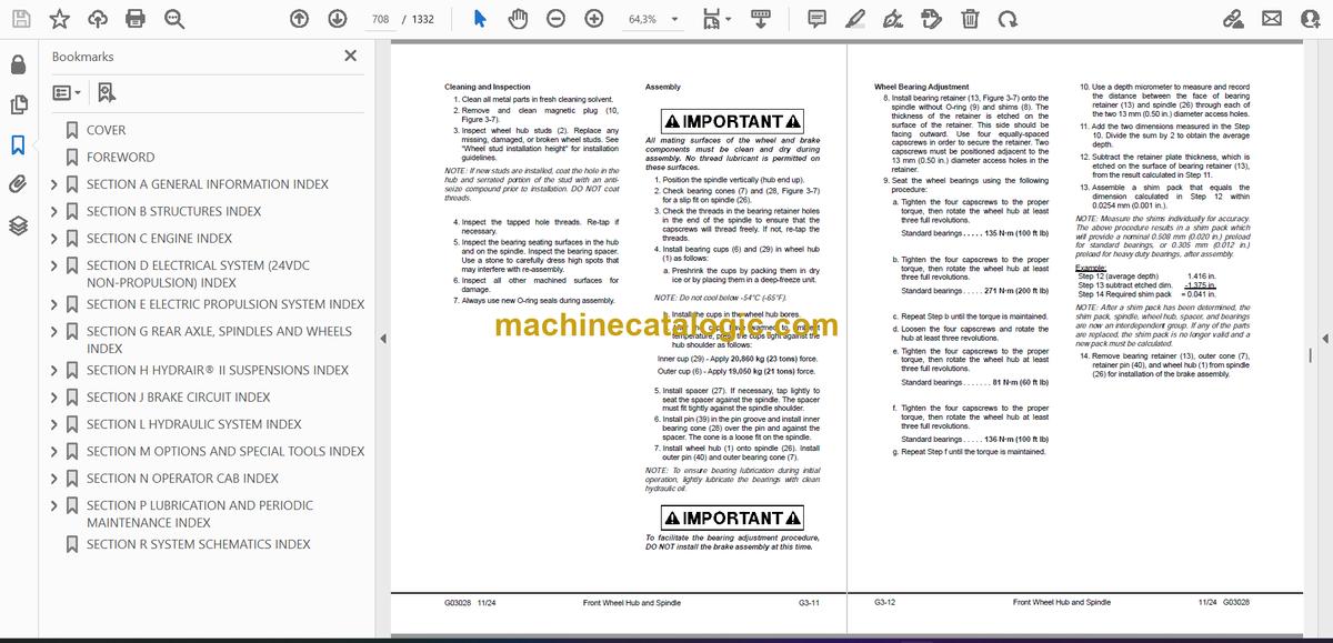
- Cleaning and Inspection
- Assembly
- Wheel Bearing Adjustment
- Brake Installation
- Seal Assembly Gap Check
- WHEEL SPEED SENSOR TESTING
- STEERING CYLINDERS
- Spherical Bearing Wear Limits
- Removal
- Installation
- Bearing Replacement (Steering Cylinder and Tie Rod)
- TIE ROD
- Removal
- Installation
- Disassembly
- Assembly
- Toe-In Adjustment
- TIE ROD INSPECTION AND TORQUE PROCEDURE
- Old Style Tie Rod
- New Style Tie Rod
- SECTION G4 REAR AXLE MOUNTING INDEX
- REAR AXLE MOUNTING
- PIVOT PIN
- PIVOT EYE BEARING
- PIVOT EYE REPAIR
- Removal
- Disassembly
- Assembly
- Installation
- ANTI-SWAY BAR
- Removal
- Disassembly
- Cleaning and Inspection
- Assembly
- Installation
- SECTION G5 REAR AXLE AND WHEEL MOTOR INDEX
- REAR AXLE AND WHEEL MOTOR
- REAR AXLE HOUSING
- Preparation
- Removal
- Cleaning and Inspection
- Installation
- BLOWER PRESSURE SWITCH ADJUSTMENT
- WHEEL MOTOR
- Preparation
- Removal
- Cleaning and Inspection
- Installation
- WHEEL MOTOR GEAR OIL
- TEMPERATURE CONSTRAINTS – TRUCK OPERATION
- PROPER STORAGE AND HANDLING OF GEAR oil TO AVOID CONTAMINATION
- Filtering Requirements
- Particle Size Analysis
- Flushing
- Spectrographic Oil Sample Analysis
- ELEMENT SPECIFICATION CHARTS
- SECTION H HYDRAIR® II SUSPENSIONS INDEX
- SECTION H2 FRONT SUSPENSIONS INDEX
- FRONT SUSPENSION
- Removal
- Installation
- Inspection
- LOWER BEARING & SEALS
- MAJOR SUSPENSION REBUILD
- SUSPENSION PRESSURE TEST
- SECTION H3 REAR SUSPENSIONS INDEX
- REAR SUSPENSIONS
- SUSPENSION CYLINDER
- Removal
- Installation
- Disassembly
- Cleaning and Inspection
- Assembly
- SUSPENSION PRESSURE TEST
- SECTION H4 SUSPENSION OILING AND CHARGING PROCEDURES INDEX
- SUSPENSION OILING AND CHARGING PROCEDURES
- CHECKING FOR IMPROPER SUSPENSION CHARGE
- GENERAL
- REQUIRED EQUIPMENT
- HYDRAIR® CHARGING KIT
- Installation of Charging Kit
- Removal of Charging Kit
- SUPPORT BLOCKS FOR OILING AND CHARGING DIMENSIONS
- FRONT SUSPENSION
- REAR SUSPENSION
- OIL AND NITROGEN SPECIFICATIONS CHARTS
- SECTION J BRAKE CIRCUIT INDEX
- SECTION J2 BRAKE CIRCUIT INDEX
- BRAKE CIRCUIT
- SERVICE BRAKE CIRCUIT
- PARKING BRAKE CIRCUIT
- BRAKE LOCK CIRCUIT
- SECONDARY BRAKING AND AUTOMATIC APPLY
- WARNING CIRCUIT
- SECTION J3 BRAKE CIRCUIT COMPONENT SERVICE INDEX
- BRAKE CIRCUIT COMPONENT SERVICE
- BRAKE VALVE
- Rebuild Criteria
- Removal
- Installation
- BRAKE VALVE/PEDAL ASSEMBLY
- Disassembly
- Assembly
- Installation
- DUAL RELAY VALVE
- BRAKE MANIFOLD
- Removal
- Installation
- Disassembly
- Cleaning and Inspection
- Assembly
- BRAKE ACCUMULATORS
- Accumulator charging and storage
- Temperature during precharge
- BLADDER BRAKE ACCUMULATORS
- Brake Accumulator Bleed Down Procedure
- Removal
- Installation
- Disassembly
- Cleaning and Inspection
- Assembly
- Precharge Maintenance
- Accumulator Storage Procedures
- Installing A Bladder Accumulator From Storage
- PISTON BRAKE ACCUMULATORS
- Brake Accumulator bleed down Procedure
- Removal
- Installation
- Disassembly
- Cleaning and Inspection
- Assembly
- Piston accumulator charging procedure
- Testing
- RETARDER CONTROL LEVER (STEERING COLUMN-MOUNTED)
- Removal
- Installation
- Disassembly
- Lever Adjustments
- Potentiometer Check
- Assembly
- FRONT BRAKE COOLING HOSE INSTALLATION
- SECTION J4 BRAKE CIRCUIT CHECK-OUT PROCEDURE INDEX
- BRAKE CIRCUIT CHECK-OUT PROCEDURE
- REQUIRED EQUIPMENT
- INITIAL SYSTEM SETUP
- BRAKE LOCK / SECONDARY BRAKE CHECK-OUT
- PARKING BRAKE CHECK-OUT
- SERVICE BRAKE CHECK-OUT
- LOW ACCUMULATOR PRESSURE AND AUTO APPLY CHECK-OUT
- BRAKE CIRCUIT AND BRAKE VALVE TROUBLESHOOTING CHART
- HYDRAULIC BRAKE SYSTEM CHECK-OUT PROCEDURE DATA SHEET
- HYDRAULIC BRAKE SYSTEM CHECK-OUT PROCEDURE DATA SHEET
- SECTION J5 WET DISC BRAKE ASSEMBLY INDEX
- WET DISC BRAKE ASSEMBLY
- OPERATION
- BRAKE DISC WEAR INSPECTION
- BRAKE REBUILD
- Disassembly
- Cleaning and Inspection
- Assembly
- Brake floating ring seal assembly and installation
- Brake Floating Seal Assembly and Installation
- WET DISC BRAKE BLEEDING PROCEDURE
- SECTION J7 PARKING BRAKE INDEX
- PARKING BRAKE
- OPERATION
- MAINTENANCE
- Inspection
- Removal
- Installation
- Disassembly
- Cleaning and Inspection
- Assembly
- Cleaning and Inspecting New Discs
- PARKING BRAKE BLEEDING PROCEDURE
- SECTION L HYDRAULIC SYSTEM INDEX
- SECTION L2 HYDRAULIC SYSTEM INDEX
- HYDRAULIC SYSTEM
- HYDRAULIC PUMP MODULE
- HOIST CIRCUIT OPERATION
- STEERING CIRCUIT OPERATION
- DISC BRAKE COOLING SYSTEM
- SECTION L3 HYDRAULIC SYSTEM COMPONENT REPAIR INDEX
- HYDRAULIC SYSTEM COMPONENT REPAIR
- HOIST PUMP
- Removal
- Installation
- Inspection
- Assembly
- HYDRAULIC TANK
- HYDRAULIC TANK BREATHERS
- HYDRAULIC TANK STRAINERS
- Removal
- Inspect and Clean
- Installation
- SECTION L4 STEERING CIRCUIT INDEX
- STEERING CIRCUIT
- STEERING CIRCUIT OPERATION
- COMPONENT DESCRIPTION
- Steering Control Unit
- Bleed Down Manifold
- Steering Accumulator Bleed Down Solenoid
- Relief Valves
- Hoist Up Limit Solenoid
- Steering Accumulators
- Low Precharge Warning Switch
- High Pressure Filter
- Quick Disconnect Ports
- Flow Amplifier
- FLOW AMPLIFIER SYSTEM OPERATION
- No Steer
- Steering Left
- Steering Right
- No Steer, External Shock Load
- STEERING PUMP
- Normal Operation
- High Altitude Operation
- PRINCIPLE OF OPERATION
- Full Pump Volume
- Half Pump Volume
- Neutral Position
- Steering Pump
- SECTION L5 STEERING CONTROL UNIT INDEX
- STEERING CONTROL UNIT
- REMOVAL
- SPLINE INSPECTION
- INSTALLATION
- DISASSEMBLY
- CLEANING AND INSPECTION
- ASSEMBLY
- SECTION L6 STEERING CIRCUIT COMPONENT REPAIR INDEX
- STEERING CIRCUIT COMPONENT REPAIR
- BLEEDDOWN MANIFOLD VALVE
- FLOW AMPLIFIER
- Removal
- Installation
- Disassembly
- Assembly
- STEERING CYLINDERS
- Disassembly
- Piston Seal & Bearing Installation
- Assembly
- Testing
- STEERING AND BRAKE PUMP
- Removal
- Installation
- Disassembly
- Inspection
- Assembly
- Driveshaft Group
- Rotating Group
- Valve Plate Group
- STEERING ACCUMULATORS
- Removal
- Installation
- Disassembly
- Cleaning and Inspection
- Assembly
- Leak Testing
- Charging Procedure
- Precharge Maintenance
- Accumulator Storage Procedures
- Bladder Storage Procedures
- Installing A Bladder Accumulator From Storage
- TROUBLESHOOTING CHART
- SECTION L7 HOIST CIRCUIT INDEX
- HOIST CIRCUIT
- BASIC OPERATION
- COMPONENT DESCRIPTION
- Hydraulic Tank
- Hydraulic Pump
- High Pressure Filters
- Hoist Valve
- Inlet Sections
- Work Ports (Rear) Spool Section
- Tank Ports (Front) Spool Section
- Hoist Pilot Valve
- Bleeddown Manifold
- Hoist Up Limit Solenoid
- Pilot Operated Check Valve
- Overcenter Manifold
- HOIST CIRCUIT OPERATION
- Float Position Of Pilot Valve With Truck Body On Frame
- Power Up Operation
- Hold Operation
- Power Down Operation
- Float Operation
- SECTION L8 HOIST CIRCUIT COMPONENT REPAIR INDEX
- HOIST CIRCUIT COMPONENT REPAIR
- HOIST VALVE
- Removal
- Installation
- O-Ring Replacement
- INLET SECTION
- Cleaning and Inspection
- Assembly
- REAR SPOOL SECTION (Work Ports)
- Disassembly
- Cleaning and Inspection
- Assembly
- FRONT SPOOL SECTION (Tank Ports)
- Disassembly
- Cleaning and Inspection
- Assembly
- HOIST PILOT VALVE
- Removal
- Installation
- Disassembly
- Cleaning and Inspection
- Assembly
- HOIST CYLINDERS
- Removal
- Installation
- Disassembly
- Cleaning and Inspection
- Assembly – Quill
- Assembly – Cylinder
- Testing
- OVERCENTER VALVE MANIFOLD
- SECTION L9 HYDRAULIC SYSTEM FILTERS INDEX
- HYDRAULIC SYSTEM FILTERS
- HOIST CIRCUIT FILTER
- Filter Element Replacement
- Removal – Hoist Circuit Filter
- Installation – Hoist Circuit Filter
- Indicator Switch – Hoist Circuit Filter
- STEERING CIRCUIT FILTER
- Filter Element Replacement
- Removal – Steering Circuit Filter
- Installation – Steering Circuit Filter
- Indicator Switch – Steering Circuit Filter
- INDICATOR SWITCH
- SECTION L10 HYDRAULIC CHECKOUT PROCEDURE INDEX
- HYDRAULIC CHECKOUT PROCEDURE
- GENERAL INFORMATION
- STEERING CIRCUIT CHECK-OUT & ADJUSTMENT PROCEDURE
- Equipment Requirements
- Pump Pressure Control Adjustments
- Steering Control Valve and Flow Amplifier Leakage Test
- Bleed Down Manifold Leakage Test
- STEERING/BRAKE PUMP STROKE ADJUSTMENT
- SHOCK AND SUCTION VALVES
- Equipment Requirements
- Pressure Tests
- HOIST SYSTEM RELIEF VALVE AND BRAKE COOLING CIRCUIT PRESSURES
- Equipment Requirements
- Pressure Gauge Locations
- Brake Cooling Circuit Test
- Power Up Relief Pressure Test
- Power Down Relief Pressure Test
- Counterbalance Valve Pressure Check
- Counterbalance Valve Adjustment
- 930E CHECK-OUT PROCEDURE – STEERING SYSTEM DATA SHEET
- 930E CHECK-OUT PROCEDURE – BRAKE COOLING & HOIST SYSTEM DATA SHEET
- SECTION M OPTIONS AND SPECIAL TOOLS INDEX
- SECTION M7 HOT START SYSTEM INDEX
- HOT START SYSTEM
- SYSTEM OPERATION
- HEATER INFORMATION
- TROUBLESHOOTING GUIDELINES
- SECTION M8 SPECIAL TOOLS
- HIGH VOLTAGE TOOLS
- 0-2000 VDC CUSTOM METER KIT (58B-06-00800)
- SECTION M19 RADIATOR SHUTTERS INDEX
- RADIATOR SHUTTERS
- OPERATION
- Hydraulic Circuit
- Electrical Circuit
- MAINTENANCE AND REPAIR
- TROUBLESHOOTING
- SECTION M20 PAYLOAD METER III ™ INDEX
- OPERATION SECTION
- Introduction
- Data Summary
- Data Gathering
- COMPONENT DESCRIPTION
- System Diagram
- Suspension Pressure Sensors
- Inclinometer
- Operator Display
- Operator Switch
- Speed Input
- Body-Up Switch
- Brake Lock Switch
- Payload Meter
- Communications Ports
- Key Switch Input
- Payload Meter Power
- Load Lights
- Wiring and Termination
- TCI Outputs
- OPERATOR’S DISPLAY AND SWITCH
- Reading the Speedometer/Digital Display
- Reading the Load Display
- Using the Operator ID
- Using the Load and Ton Counter
- Total Ton Counter
- Total Load Counter
- Clearing the Counters
- Viewing Live Sensor Data
- Other Display Messages
- PAYLOAD OPERATION & CALCULATION
- Description of Haul Cycle States
- Haul Cycle Description
- Load Calculation
- Carry Back
- Measurement Accuracy
- SOURCES FOR PAYLOAD ERROR
- Payload Error
- Loading Conditions
- Pressure Sensors
- Swingloads
- Speed and Distance
- HAUL CYCLE DATA
- Haul Cycle Warning Flags
- Frame Torque Data
- Sprung Weight Data
- Maximum Speed Data
- Alarm Records
- Fault Code Data
- PC SOFTWARE OVERVIEW
- System Configuration
- Installing the PLMIII Software
- DOWNLOADING DATA
- PLM III SYSTEM CONFIGURATION
- Starting Communications
- Displayed Payload Units
- Time Units
- Connection Menu
- Connecting to the Payload Meter
- Configure the Payload Meter
- Setting the Date and Time
- Setting the Truck Type
- Setting the Gauge Display Units
- Setting the Frame Serial Number
- Setting the Truck Number
- Setting the Komatsu Distributor
- Setting the Komatsu Customer
- Clean Truck Tare Calibration
- Inclinometer Calibration
- DATA ANALYSIS
- Creating a Query
- Sorting on Truck Unit Number
- Sorting on Truck Type
- Sorting on Date Range
- Sorting on Time Range
- Payload Detail Screen
- Creating Reports
- Summary – one page report
- Detailed – multi-page report
- Creating Graphs
- Exporting Data
- CSV Export
- Compressed
- Importing Data
- Deleting Haul Cycle Records
- Viewing Alarms
- Deleting Alarm Records
- TROUBLESHOOTING SECTION
- TROUBLESHOOTING
- Viewing Active Alarms
- Real-Time Data Display
- Testing the Payload Lights
- Creating Log Files of Inputs
- Daily Inspections
- Periodic Maintenance
- Abnormal Displays at Power-Up
- No Payload Display When Key Switch is Turned ON
- No Display on Speedometer
- No Display on Operator Display
- No Communications With PC
- Load Lights Don’t Light During Loading
- Load Lights Remain ON
- Load Lights Remain ON During Dumping
- Display Doesn't Clear When The Load Is Dumped
- Calibration Problems
- Alarm 1 – Left Front Pressure High
- Alarm 2 – Left Front Pressure Low
- Troubleshoot Wiring to Left Front Suspension
- Alarm 3 – Right Front Pressure High
- Alarm 4 – Right Front Pressure Low
- Troubleshoot Wiring to Right Front Suspension
- Alarm 5 -Left Rear Pressure High
- Alarm 6 – Left Rear Pressure Low
- Troubleshoot Wiring to Left Rear Suspension
- Alarm 7 – Right Rear Pressure High
- Alarm 8 – Right Rear Pressure Low
- Troubleshoot Wiring to Right Rear Suspension
- Alarm 9 – Inclinometer High
- Alarm 10 – Inclinometer Low
- Troubleshoot Inclinometer Wiring
- Alarm 13 – Body Up Input Failure
- Alarm 16 – Memory Write Failure
- Alarm 17 – Memory Read Failure
- Alarm 18
- Alarm 19
- Alarm 22
- Operator Switch Doesn't Work
- Alarm 26 – User Switch Fault – SELECT
- Alarm 27 – User Switch Fault – SET
- Connector Map
- Connectors
- PLMIII CHECK OUT PROCEDURE
- General Description
- Tools Required
- Checkout Procedure
- PLMIII CHECKOUT PROCEDURE CONFIRMATION
- Flashburn Programming
- Confirmation Checklist
- SECTION M31 RESERVE ENGINE OIL SYSTEM INDEX
- RESERVE ENGINE OIL SYSTEM
- Operation
- LED Monitor Light
- Tank Fill Control (Optional)
- Filling Procedure (Remote Fill Feature)
- SERVICE
- Every 10 Hours, or once each shift:
- Every 500 Hours
- Changing Oil
- TROUBLESHOOTING
- SYSTEM ELECTRICAL SCHEMATICS
- SECTION N OPERATOR CAB INDEX
- SECTION N2 TRUCK CAB AND COMPONENTS INDEX
- TRUCK CAB AND COMPONENTS
- TRUCK CAB
- Description
- Removal
- Installation
- CAB DOOR
- Removal
- Installation
- Door Jamb Bolt Adjustment
- Door Handle Plunger Adjustment
- Replacing the Door Glass
- Replacing the Door Handle or Latch Assembly
- Replacing the Door Window Regulator
- Replacing the Door and Door Hinge Seal
- Replacing the Door Opening Seal
- GLASS REPLACEMENT (Adhesive-Bonded Windows)
- Recommended Tools and Supplies
- Replacement Procedure
- WINDSHIELD AND REAR GLASS
- SECTION N3 CAB COMPONENTS INDEX
- CAB COMPONENTS
- WINDSHIELD WIPERS
- WIPER MOTOR
- WIPER ARM
- WIPER LINKAGE
- WINDSHIELD WASHER
- OPERATOR SEAT
- Seat Belts
- Adjustment
- Inspection
- Removal
- Installation
- PASSENGER SEAT
- Inspection
- Removal
- Installation
- SECTION N4 HEATER / AIR CONDITIONER (EK7945) INDEX
- HEATER/AIR CONDITIONER
- OPERATION
- Fan Control Knob
- Temperature Control Knob
- Directional Control Knob
- Heater Vents
- COMPONENTS
- Fuse and Circuit Breaker
- Relays
- Heater Core
- Fan Motor And Speed Control
- Actuators
- Cab Air Filter
- ENVIRONMENTAL IMPACT OF AIR CONDITIONING
- AIR CONDITIONING FOR OFF-HIGHWAY VEHICLES
- PRINCIPLES OF REFRIGERATION
- Air Conditioning
- Refrigeration – The Act Of Cooling
- The Refrigeration Cycle
- AIR CONDITIONER SYSTEM COMPONENTS
- Compressor (Refrigerant Pump)
- Service Valves
- Condenser
- Receiver-Drier
- Expansion Block Valve
- Accumulator
- Evaporator
- ELECTRICAL CIRCUIT
- Thermostat
- Compressor Clutch
- Trinary™ Switch
- AIR CONDITIONING SYSTEM SERVICING WARNINGS
- SERVICE TOOLS AND EQUIPMENT
- Recovery/Recycle Station
- Leak Detector
- Manifold Gauge Set
- Installing Manifold Gauge Set
- Purging Air From Service Hoses
- Service Valves
- Vacuum Pump
- SYSTEM PERFORMANCE TEST
- SYSTEM OIL
- Handling and Reusing PAG Oil
- Oil Quantity
- Checking System Oil
- REFRIGERANT
- Recycled Refrigerant
- Reclaimed Refrigerant
- Refrigerant Quantity
- R-134a Refrigerant Containers
- SYSTEM LEAK TESTING
- Electronic Leak Detector
- Tracer Dyes
- Soap and Water
- RECOVERING AND RECYCLING THE REFRIGERANT
- Draining Oil from the Previous Recovery Cycle
- Performing the Recovery Cycle
- Performing the Recycling Procedure
- Evacuating and Charging the A/C System
- SYSTEM REPAIR
- A/C DRIVE BELT CHECKOUT PROCEDURE
- Pulley Alignment
- Belt Tension Check
- COMPONENT REPLACEMENT
- Hoses and Fittings
- Lines
- Expansion Valve
- Receiver-Drier
- Thermostat
- Compressor
- Accumulator
- Clutch
- Servicing the Compressor Clutch
- Pulley Removal
- Clutch Coil Check
- Pulley Installation
- Clutch Assembly Installation
- EVACUATING THE SYSTEM
- CHARGING THE A/C SYSTEM
- TROUBLESHOOTING
- Preliminary Checks
- Diagnosis Of Gauge Readings And System Performance
- TROUBLESHOOTING BY MANIFOLD GAUGE SET READINGS
- PREVENTIVE MAINTENANCE SCHEDULE FOR A/C SYSTEM
- SECTION N5 OPERATOR CAB CONTROLS INDEX
- OPERATOR CAB CONTROLS
- STEERING COLUMN
- Removal
- Inspection
- Installation
- STEERING WHEEL
- STEERING WHEEL AND CONTROLS
- Horn Button
- Tilt / Telescope Lever
- Multi-Function Turn Signal Switch
- DYNAMIC RETARDING
- Retarder Lever
- Brake/Retarder Pedal
- Throttle/Accelerator Pedal
- GRADE/SPEED CHART
- OVERHEAD PANEL AND DISPLAYS
- Speakers
- Warning Alarm Buzzer
- Radio/CD Player
- Warning Indicator Light Dimmer Control
- Status/Warning Indicator Light Panel
- Air Cleaner Restriction Gauges
- CENTER CONSOLE
- Directional Control Lever
- Override/Fault Reset Switch
- Engine Shutdown Switch
- Window Control Switches
- Hoist Control Lever
- Retarder Speed Control (RSC) Adjustment Dial
- Retarder Speed Control (RSC) Switch
- Data Store Button
- KOMTRAX Plus Snapshot In Progress Light
- Link Energized Light
- Service Engine Light
- 12V Auxiliary Power Outlets
- DIAGNOSTIC PORTS
- KOMTRAX Plus Diagnostic Port
- Interface Module (IM) Diagnostic Port
- Payload Meter Diagnostic Port
- Truck Control Interface (TCI) Diagnostic Port
- Propulsion System Controller (PSC) Diagnostic Port
- Engine Diagnostic Port (CENSE)
- Engine Diagnostic Port (QUANTUM)
- INSTRUMENT PANEL
- Control Symbols
- Key Switch
- Air Conditioner Compressor Switch
- Rotating Beacon Switch (optional)
- Heated Mirrors Switch (optional)
- AC Drive System Rest Switch
- Wheel Brake Lock Switch
- Hazard Warning Lights
- Heater/Air Conditioner Vents
- Engine Oil Pressure Gauge
- Right Turn Signal Indicator
- Digital Tachometer
- High Beam Indicator
- Speedometer/Payload Meter Display
- Left Turn Signal Indicator
- Coolant Temperature Gauge
- Lamp Check Switch
- Light Switch (3-Way)
- Ladder Light Switch
- Backup Light Switch
- Fog Light Switch
- Payload Meter Switch
- Panel Illumination Light Dimmer Switch
- Hydraulic Oil Temperature Gauge
- Engine Hourmeter
- Fuel Gauge
- OVERHEAD STATUS / WARNING INDICATORS
- A1. High Hydraulic Oil Temperature
- B1. Low Steering Pressure
- C1. Low Accumulator Precharge Pressure
- D1. Not used
- E1. Low Brake Pressure
- A2. Low Hydraulic Tank Level
- B2. Low Automatic Lubrication System Pressure
- C2. Circuit Breaker Tripped
- D2. Hydraulic Oil Filter Monitor
- E2. Low Fuel
- A3. Parking Brake
- B3. Service Brake
- C3. Body Up
- D3. Dynamic Retarding
- E3. Stop Engine
- A4. Cranking Motor Failure
- B4. Backup Lights
- C4. Engine Shutdown Timer
- D4. Retard Speed Control (RSC) Indicator
- E4. Check Engine
- A5. No Power
- B5. Propulsion System Warning
- C5. Propulsion System Temperature
- D5. System/Component Failure
- E5. Battery Charging System Failure
- A6. No Propel
- B6. Propel System At Rest
- C6. Propel System Not Ready
- D6. Reduced Propulsion
- E6. Retard At Continuous Level
- REAR AXLE LIGHT BAR
- Backup Lights
- Retard Lights
- Brake Light
- Backup Alarm
- KOMTRAX PLUS
- Operation
- Interface Module
- Basic Precautions
- KOMATSU WIRELESS BRIDGE (Optional)
- General Information
- Communication Setup
- Switching to the KWB_SETUP Network
- Setting the Computer Subnet Mask and IP Address
- Properties
- Setting Up the KWB
- Adding Encryption
- Final Computer Settings
- Data Downloading
- Resetting the KWB
- KWB Lights
- SECTION P LUBRICATION AND PERIODIC MAINTENANCE INDEX
- SECTION P2 LUBRICATION AND SERVICE INDEX
- LUBRICATION AND SERVICE
- GENERAL
- SERVICE CAPACITIES
- HYDRAULIC TANK SERVICE
- COOLING SYSTEM SERVICE
- Radiator Filling Procedure
- Coolant Specifications
- Unacceptable Practices
- WHEEL MOTOR SERVICE
- RESERVE OIL TANK SERVICE
- Filling the Reserve Oil Tank (Remote Fill)
- Inline Screen
- QUICK FILL SERVICE CENTER
- LUBRICATION CHART
- 10 HOUR (DAILY) INSPECTIONS
- 50 HOUR LUBRICATION AND MAINTENANCE CHECKS
- 100 HOUR LUBRICATION AND MAINTENANCE CHECKS
- 250 HOUR LUBRICATION AND MAINTENANCE CHECKS
- 500 HOUR LUBRICATION AND MAINTENANCE CHECKS
- 1000 HOUR LUBRICATION AND MAINTENANCE CHECKS
- 5000 HOUR MAINTENANCE CHECKS
- SECTION P3 AUTOMATIC LUBRICATION SYSTEM INDEX
- AUTOMATIC LUBRICATION SYSTEM
- GENERAL DESCRIPTION
- SYSTEM COMPONENTS
- Filter
- Hydraulic Motor and Pump
- Grease Reservoir
- Pressure Reducing Valve
- Flow Control Valve
- Solenoid Valve
- Vent Valve
- Lubrication Cycle Timer
- Over Pressure Cut Off Switch
- Grease Pressure Failure Switch
- Injectors
- Relief Valve (unloader valve)
- SYSTEM OPERATION
- Normal Operation
- Lubricant Required For System
- System Priming
- Filter Assembly
- LUBRICANT PUMP
- Pump Housing Oil Level
- Pump Pressure Control
- INJECTORS (SL-1 Series “H”)
- Injector Specifications
- Injector Adjustment
- INJECTOR OPERATION
- PREVENTIVE MAINTENANCE PROCEDURES
- Daily Lubrication System Inspection
- 250 Hour Inspection
- 1000 Hour Inspection
- SYSTEM CHECKOUT
- Lubrication Controller Check
- Lubrication Controller Components
- Lubrication Controller Adjustment
- SYSTEM TROUBLESHOOTING CHART
- SECTION R SYSTEM SCHEMATICS INDEX
Komatsu


