This Komatsu 107E-3 Series Engine Shop Manual (SEN06655-05) is aimed at the engine itself, not the whole machine it’s bolted into. It’s what shops and field techs grab when an engine won’t start, runs rough, smokes, or needs teardown and rebuild work. If you’re trying to keep downtime down and make the right call on repair vs. swap, this is the kind of book you want in your truck or on the laptop.
What this manual helps you do
- Trace fuel, air, and lubrication system issues step by step so you’re not just throwing parts at a no-start or low-power complaint.
- Check wear patterns and failure points during disassembly so you can decide what’s reusable and what really needs replacing.
- Follow correct engine teardown and reassembly sequences so you don’t crack housings, pinch seals, or miss hidden fasteners.
- Diagnose abnormal noise, smoke, or temperature problems using the kind of tests most shops can do with standard tools.
- Handle timing, adjustments, and basic setup checks after repair so the 107E-3 engine starts clean and runs the way it should.
Who this is for
This manual fits field technicians, shop mechanics, and fleet managers who are actually repairing or overhauling Komatsu 107E-3 Series Engines. If you just need daily checks or operating tips, you’re better off with the operation and maintenance manual instead of this shop manual.
FAQ
Q: Is this a PDF I can search and print?
A: Yes, it’s a digital PDF that you can search by keyword and print pages or sections you need in the field.
Q: Does it go deep enough for full rebuild work?
A: These shop manuals usually cover diagnostic procedures, disassembly/assembly sequences, and adjustment guidance for workshop-level repairs on the 107E-3 engine.
Q: How do I know it matches my exact engine variant?
A: Check your engine’s ID plate and confirm it’s a Komatsu 107E-3 Series Engine, then match that to the book reference SEN06655-05 before you buy.
Bottom line: If you’re tearing into or troubleshooting a Komatsu 107E-3 Series Engine, this shop manual is what you want; if you’re only doing basic operator service, keep looking for the O&M book.
📘 Show Index
Table of Contents:
- 00 Index and Foreword
- Index
- Abbreviation List
- Foreword, Safety, Basic Information
- How to Read the Engine Shop Manual
- Safety Notice for Operation
- Precautions to Prevent Fire
- Procedures If Fire Occurs
- Precautions for Disposing of Waste Materials
- Engine Technology to Conform Exhaust Gas Emission
- Precautions for DEF
- General Character and Precautions for Handling
- Precautions for Adding
- Precautions for Storage
- Precautions for Fire Hazard and Leakage
- Other Precautions
- Store DEF
- Precautions When You Handle Hydraulic Equipment
- Precautions When You Disconnect and Connect Pipings
- Precautions When You Handle Electrical Equipment
- Precautions When You Handle Fuel System Equipment
- Precautions When You Handle Intake System Equipment
- Disconnect and Connect Push-Pull Type Coupler
- How to Disconnect and Connect Type 1 Push-Pull Type Coupler
- How to Disconnect and Connect Type 2 Push-Pull Type Coupler
- How to Disconnect and Connect Type 3 Push-Pull Type Coupler
- Precautions for Disconnection and Connection of Connectors
- How to Disconnect and Connect Deutsch Connector
- How to Disconnect and Connect Slide Lock Type Connector
- How to Disconnect and Connect Connector with Lock to Pull
- How to Disconnect and Connect Connector with Lock to Push
- How to Disconnect and Connect Connector with Housing to Rotate
- How to Read the Codes for Electric Cable
- Explanation of Terms for Maintenance Standard
- Standard Tightening Torque Table
- Conversion Table
- 01 Specifications
- Table of Contents
- Abbreviation List
- Specifications
- Outline of Exhaust Gas Regulation
- System Diagram of Engine Conformed to Tier4 Regulation
- Improvement of Engine Conformed to Tier4 Regulation
- List of Applicable Machines: 107E-3
- Specifications
- Specifications: SAA4D107E-3 (FH100-1, FH120-1, FH135-1, FH160-1)
- Engine General View
- Engine General View: SAA4D107E-3 (FH100-1, FH120-1, FH135-1, FH160-1)
- Engine Performance Curve
- Engine Performance Curve: SAA4D107E-3 (FH100-1, FH120-1, FH135-1, FH160-1)
- 10 Structure and Function
- Table of Contents
- Abbreviation List
- Urea SCR System
- Layout Drawing of Urea SCR System
- Urea SCR System Diagram
- Function of Urea SCR System
- Function of DEF System
- Inducement Strategy
- Component Parts of Urea SCR System
- DEF Mixing Tube
- SCR Assembly
- DEF Tank
- DEF Pump
- DEF Injector
- DEF Hose
- DEF Tank Heating Valve
- Engine System
- Layout of Engine Components
- Layout Drawing of Engine Components
- Intake and Exhaust System Parts
- Layout Drawing of Intake and Exhaust System
- Intake and Exhaust System Circuit Diagram
- Function of Intake and Exhaust System
- Air Cleaner
- Intake Air Heater
- Engine Main Body Parts
- Cylinder Head
- Cylinder Block
- Main Drive Parts
- Timing Gear
- Front Cover
- Valve System
- Flywheel and Flywheel Housing
- Turbocharger System
- Circuit Diagram of VGT System
- Function of VGT System
- VGT
- EGR System
- EGR Valve
- EGR Cooler
- KCCV System
- KCCV Ventilator
- KDOC
- Lubrication System
- Layout Drawing of Lubrication System Parts
- Lubrication System Circuit Diagram
- Engine Oil Pump
- Engine Oil Filter
- Engine Oil Cooler
- Engine Oil Regulator Valve
- Safety Valve of Engine Oil
- Engine Oil Pan
- Fuel System
- Layout Drawing of Fuel System Parts
- Fuel System Circuit Diagram
- Function of Fuel System
- Supply Pump
- Fuel Prefilter
- Fuel Main Filter
- Cooling System
- Layout Drawing of Cooling System Parts
- Cooling System Circuit Diagram
- Drive Pulley
- Water Pump
- Thermostat
- Electrical System
- Component Parts of Electrical System
- Alternator
- Starting Motor
- Engine Wiring Harness
- Engine Controller
- Sensor
- Layout Drawing of Engine Sensor
- Structure of Ambient Pressure Sensor
- Function of Ambient Pressure Sensor
- Structure of Engine Oil Pressure Switch
- Function of Engine Oil Pressure Switch
- Structure of Charge (Boost) Pressure and Temperature Sensor
- Function of Charge (Boost) Pressure and Temperature Sensor
- Structure of Coolant Temperature Sensor
- Function of Coolant Temperature Sensor
- Structure of NE (Crankshaft) Speed Sensor
- Function of NE (Crankshaft) Speed Sensor
- Structure of Bkup (Camshaft) Speed Sensor
- Function of Bkup (Camshaft) Speed Sensor
- Structure of Common Rail Pressure Sensor
- Function of Common Rail Pressure Sensor
- Structure of VGT Speed Sensor
- Function of VGT Speed Sensor
- Structure of Mass Air Flow and Temperature Sensor
- Function of Mass Air Flow and Temperature Sensor
- Structure of Crankcase Pressure Sensor
- Function of Crankcase Pressure Sensor
- Structure of Air Cleaner Clogging Sensor
- Function of Air Cleaner Clogging Sensor
- Structure of Water-in-Fuel Sensor
- Function of Water-in-Fuel Sensor
- Structure of EGR Valve (with Built-in Position Sensor)
- Function of EGR Valve (with Built-in Position Sensor)
- Structure of Exhaust Manifold Pressure Sensor
- Function of Exhaust Manifold Pressure Sensor
- Structure of EGR Orifice Temperature Sensor
- Function of EGR Orifice Temperature Sensor
- Structure of VGT Actuator (with Built-in Position Sensor)
- Function of VGT Actuator (with Built-in Position Sensor)
- 20 Standard Value Table
- Table of Contents
- Abbreviation List
- Standard Value Table for Engine
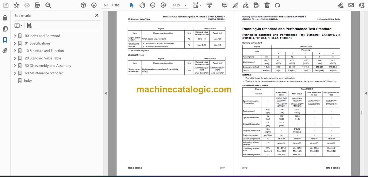
- Standard Value Table for Engine: SAA4D107E-3 (FH100-1, FH120-1, FH135-1, FH160-1)
- Running-in Standard and Performance Test Standard
- Running-in Standard and Performance Test Standard: SAA4D107E-3 (FH100-1, FH120-1, FH135-1, FH160-1)
- 50 Disassembly and Assembly
- Table of Contents
- Precautions Before Work
- Abbreviation List
- Related Information on Disassembly and Assembly
- How to Read This Manual
- Coating Materials List
- Special Tool List
- Sketches of Special Tools
- Engine System
- Disassemble and Assemble Engine Generally (4D107E-3)
- How to Disassemble Engine Generally (4D107E-3)
- How to Assemble Engine Generally (4D107E-3)
- Remove and Install Supply Pump Assembly (4D107E-3)
- How to Remove Supply Pump Assembly (4D107E-3)
- How to Install Supply Pump Assembly (4D107E-3)
- Remove and Install Engine Front Oil Seal (4D107E-3)
- How to Remove Engine Front Oil Seal (4D107E-3)
- How to Install Engine Front Oil Seal (4D107E-3)
- Remove and Install Engine Rear Oil Seal (4D107E-3)
- How to Remove Engine Rear Oil Seal (4D107E-3)
- How to Install Engine Rear Oil Seal (4D107E-3)
- 60 Maintenance Standard
- Table of Contents
- Abbreviation List
- Engine System
- Intake and Exhaust System Parts
- Maintenance Standard for VGT
- Engine Main Body Parts
- Maintenance Standard for Cylinder Head
- Maintenance Standard for Cylinder Block
- Maintenance Standard for Crankshaft
- Maintenance Standard for Piston
- Maintenance Standard for Connecting Rod
- Maintenance Standard for Timing Gear
- Maintenance Standard for Camshaft
- Maintenance Standard for Valve and Valve Guide
- Maintenance Standard for Rocker Arm
- Maintenance Standard for Tappet
- Maintenance Standard for Flywheel
- Lubrication System
- Maintenance Standard for Engine Oil Pump
- Index
Komatsu


