This Komatsu 95E-7 Series, SAA4D95LE-7 Engine Shop Manual (SEN06590-10) is aimed at the engine that sits in mid-size construction and industrial machines, doing daily hard work on sites and in yards. The folks who reach for this kind of book are usually shop mechanics, field techs, and rebuilders, not casual operators. They’re trying to chase down hard faults, do in-frame and out-of-frame rebuilds, and put engines back together so they actually last.
What this manual helps you do
- Trace engine faults using the kind of step-by-step diagnostic routines most shops follow for no-start, smoke, power loss, and overheating issues.
- Check and set engine timing, fuel system components, and control linkages during repair or overhaul.
- Follow teardown and reassembly sequences for the Komatsu 95E-7 Series, SAA4D95LE-7 engine so parts come off and go back on in the right order.
- Diagnose lubrication and cooling system problems with the usual tests, inspections, and decision trees you’d expect in a factory shop manual.
- Handle cylinder head, block, and rotating assembly work with the guidance you’d normally use during a full workshop-level rebuild.
Who this is for
This is a shop-level manual for mechanics, field technicians, and serious DIY owners who actually pull engines apart. If you just want daily checks, warning light meanings, or basic service intervals, you’re really looking for the operation and maintenance manual instead.
FAQ
Q: Is this a PDF I can download and search?
A: Yes, it’s a PDF you can download, search by keyword, and print pages for use in the shop.
Q: Does it go deep enough for a full rebuild?
A: The Komatsu 95E-7 Series, SAA4D95LE-7 Engine Shop Manual walks through diagnostic procedures, disassembly sequences, and reference torque tables used during workshop-level repairs.
Q: How do I know it matches my engine version?
A: You’ll want to match your engine’s identification plate to the 95E-7 Series, SAA4D95LE-7 designation and the SEN06590-10 reference before buying.
Bottom line: if you’re tearing into this Komatsu engine beyond basic maintenance, this is the right book; if you just run the machine and change filters, keep looking for the operator/maintenance manual instead.
📘 Show Index
Table of Contents:
- 00 Index and Foreword
- Index
- Abbreviation List
- Foreword, Safety, Basic Information
- How to Read the Engine Shop Manual
- Safety Notice for Operation
- Precautions to Prevent Fire
- Procedures If Fire Occurs
- Precautions for Disposing of Waste Materials
- Engine Technology to Conform Exhaust Gas Emission
- Precautions for DEF
- General Character and Precautions for Handling
- Precautions for Adding
- Precautions for Storage
- Precautions for Fire Hazard and Leakage
- Other Precautions
- Store DEF
- Precautions When You Handle Hydraulic Equipment
- Precautions When You Disconnect and Connect Pipings
- Precautions When You Handle Electrical Equipment
- Precautions When You Handle Fuel System Equipment
- Precautions When You Handle Intake System Equipment
- Disconnect and Connect Push-Pull Type Coupler
- How to Disconnect and Connect Type 1 Push-Pull Type Coupler
- How to Disconnect and Connect Type 2 Push-Pull Type Coupler
- How to Disconnect and Connect Type 3 Push-Pull Type Coupler
- Precautions for Disconnection and Connection of Connectors
- How to Disconnect and Connect Deutsch Connector
- How to Disconnect and Connect Slide Lock Type Connector
- How to Disconnect and Connect Connector with Lock to Pull
- How to Disconnect and Connect Connector with Lock to Push
- How to Disconnect and Connect Connector with Housing to Rotate
- How to Read the Codes for Electric Cable
- Explanation of Terms for Maintenance Standard
- Standard Tightening Torque Table
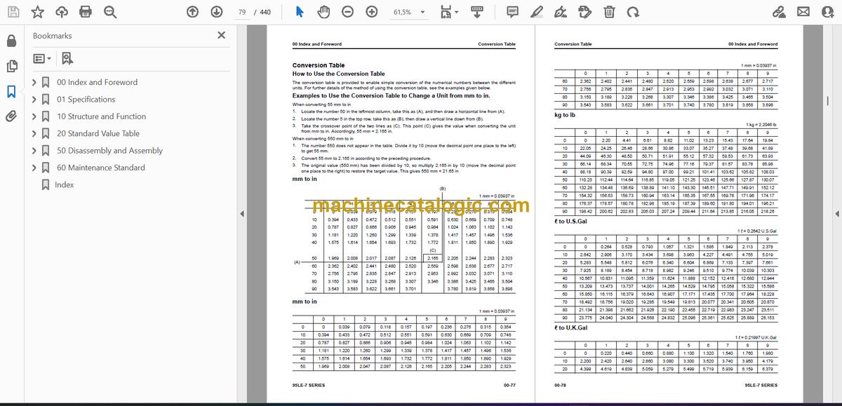
- Conversion Table
- 01 Specifications
- Table of Contents
- Abbreviation List
- Specifications
- Outline of Exhaust Gas Regulation
- System Diagram of Engine Conformed to Tier4 Regulation
- Improvement of Engine Conformed to Tier4 Regulation
- List of Applicable Machines: 95LE-7
- Specifications
- Specifications: SAA4D95LE-7 (D37EX-24, D37EXI-24, D37PX-24, D37PXI-24)
- Specifications: SAA4D95LE-7 (D39EX-24, D39EXI-24, D39PX-24, D39PXI-24)
- Specifications: SAA4D95LE-7 (PC130-11, PC130LC-11)
- Specifications: SAA4D95LE-7 (PC138US-11, PC138USLC-11, PC138US-11E0)
- Specifications: SAA4D95LE-7 (PC158USLC-12, PC158USLCI-12)
- Engine General View
- Engine General View: SAA4D95LE-7 (D37EX-24, D37EXI-24, D37PX-24, D37PXI-24, D39EX-24, D39EXI-24, D39PX-24, D39PXI-24)
- Engine General View: SAA4D95LE-7 (PC130-11, PC130LC-11)
- Engine General View: SAA4D95LE-7 (PC138US-11, PC138USLC-11, PC138US-11E0)
- Engine General View: SAA4D95LE-7 (PC158USLC-12, PC158USLCI-12)
- Weight Table
- Engine Performance Curve
- Engine Performance Curve: SAA4D95LE-7 (D37EX-24, D37EXI-24, D37PX-24, D37PXI-24)
- Engine Performance Curve: SAA4D95LE-7 (D39EX-24, D39EXI-24, D39PX-24, D39PXI-24)
- Engine Performance Curve: SAA4D95LE-7 (PC130-11, PC130LC-11)
- Engine Performance Curve: SAA4D95LE-7 (PC138US-11, PC138USLC-11, PC138US-11E0)
- Engine Performance Curve: SAA4D95LE-7 (PC158USLC-12, PC158USLCI-12)
- 10 Structure and Function
- Table of Contents
- Abbreviation List
- Urea SCR System
- Layout Drawing of Urea SCR System
- System Diagram of Urea SCR System (For the Engines Complied with Tier 4 Final Regulation)
- System Diagram of Urea SCR System (For the Engines Complied with EU Stage V Regulation)
- Function of Urea SCR System
- Function of DEF System
- Inducement Strategy
- Component Parts of Urea SCR System
- DEF Mixing Tube
- SCR Assembly
- DEF Tank
- DEF Pump
- DEF Injector
- DEF Hose
- DEF Tank Heating Valve
- Engine System
- Layout of Engine Components
- Layout Drawing of Engine Components
- Intake and Exhaust System Parts
- Layout Drawing of Intake and Exhaust System
- Intake and Exhaust System Circuit Diagram
- Function of Intake and Exhaust System
- Air Cleaner
- Intake Air Heater
- Engine Main Body Parts
- Cylinder Head
- Cylinder Block
- Main Drive Parts
- Timing Gear
- Front Cover
- Valve System
- Flywheel and Flywheel Housing
- Turbocharger System
- Variable Flow Turbocharger
- EGR System
- EGR Valve
- EGR Cooler
- KCCV System
- KCCV Ventilator
- Exhaust Throttle Valve
- KDOC
- KDPF
- Lubrication System
- Layout Drawing of Lubrication System Parts
- Lubrication System Circuit Diagram
- Engine Oil Pump
- Engine Oil Filter
- Engine Oil Cooler
- Engine Oil Pan
- Fuel System
- Layout Drawing of Fuel System Parts
- Fuel System Circuit Diagram
- Function of Fuel System
- Supply Pump
- Common Rail
- Injector
- Fuel Prefilter
- Fuel Main Filter
- Cooling System
- Layout Drawing of Cooling System Parts
- Cooling System Circuit Diagram
- Drive Pulley
- Water Pump
- Thermostat
- Jiggle Valve
- Electrical System
- Component Parts of Electrical System
- Alternator
- Starting Motor
- Engine Wiring Harness
- Engine Controller
- Sensor
- Layout Drawing of Engine Sensor (For the Engines Complied with Tier 4 Final Regulation)
- Layout Drawing of Engine Sensor (For the Engines Complied with EU Stage V Regulation)
- Structure of Ambient Pressure Sensor
- Function of Ambient Pressure Sensor
- Structure of Engine Oil Pressure Switch
- Function of Engine Oil Pressure Switch
- Structure of Charge (Boost) Pressure and Temperature Sensor
- Function of Charge (Boost) Pressure and Temperature Sensor
- Structure of Coolant Temperature Sensor
- Function of Coolant Temperature Sensor
- Structure of NE (Crankshaft) Speed Sensor
- Function of NE (Crankshaft) Speed Sensor
- Structure of Bkup (Camshaft) Speed Sensor
- Function of Bkup (Camshaft) Speed Sensor
- Structure of Common Rail Pressure Sensor
- Function of Common Rail Pressure Sensor
- Structure of Mass Air Flow and Temperature Sensor
- Function of Mass Air Flow and Temperature Sensor
- Structure of KDPF Differential Pressure and Outlet Pressure Sensor
- Function of KDPF Differential Pressure and Outlet Pressure Sensor
- Structure of Crankcase Pressure Sensor
- Function of Crankcase Pressure Sensor
- Structure of Engine Oil Level Sensor
- Function of Engine Oil Level Sensor
- Structure of Air Cleaner Clogging Sensor
- Function of Air Cleaner Clogging Sensor
- Structure of EGR Valve (with Built-in Position Sensor)
- Function of EGR Valve (with Built-in Position Sensor)
- Structure of Variable Flow Turbocharger Motor (with Built-in Position Sensor)
- Function of Variable Flow Turbocharger Motor (with Built-in Position Sensor)
- Structure of Exhaust Throttle Valve (with Built-in Position Sensor)
- Function of Exhaust Throttle Valve (with Built-in Position Sensor)
- 20 Standard Value Table
- Table of Contents
- Abbreviation List
- Standard Value Table for Engine
- Standard Value Table for Engine: SAA4D95LE-7 (D37EX-24, D37EXI-24, D37PX-24, D37PXI-24, D39EX-24, D39EXI-24, D39PX-24, D39PXI-24)
- Standard Value Table for Engine: SAA4D95LE-7 (PC130-11, PC130LC-11)
- Standard Value Table for Engine: SAA4D95LE-7 (PC138US-11, PC138USLC-11, PC138US-11E0)
- Standard Value Table for Engine: SAA4D95LE-7 (PC158USLC-12, PC158USLCI-12)
- Running-in Standard and Performance Test Standard
- Running-in Standard and Performance Test Standard: SAA4D95LE-7 (D37EX-24, D37EXI-24, D37PX-24, D37PXI-24)
- Running-in Standard and Performance Test Standard: SAA4D95LE-7 (D39EX-24, D39EXI-24, D39PX-24, D39PXI-24)
- Running-in Standard and Performance Test Standard: SAA4D95LE-7 (PC130-11, PC130LC-11)
- Running-in Standard and Performance Test Standard: SAA4D95LE-7 (PC138US-11, PC138USLC-11, PC138US-11E0)
- Running-in Standard and Performance Test Standard: SAA4D95LE-7 (PC158USLC-12, PC158USLCI-12)
- 50 Disassembly and Assembly
- Table of Contents
- Precautions Before Work
- Abbreviation List
- Related Information on Disassembly and Assembly
- How to Read This Manual
- Coating Materials List
- Special Tool List
- Sketches of Special Tools
- Engine System
- Disassemble and Assemble Engine Generally
- How to Disassemble Engine Generally
- How to Assemble Engine Generally
- Remove and Install Supply Pump Assembly
- How to Remove Supply Pump Assembly
- How to Install Supply Pump Assembly
- Remove and Install Engine Front Oil Seal
- How to Remove Engine Front Oil Seal
- How to Install Engine Front Oil Seal
- Remove and Install Engine Rear Oil Seal
- How to Remove Engine Rear Oil Seal
- How to Install Engine Rear Oil Seal
- 60 Maintenance Standard
- Table of Contents
- Abbreviation List
- Engine System
- Intake and Exhaust System Parts
- Maintenance Standard for Variable Flow Turbocharger
- Engine Main Body Parts
- Maintenance Standard for Cylinder Head
- Maintenance Standard for Cylinder Block
- Maintenance Standard for Crankshaft
- Maintenance Standard for Piston
- Maintenance Standard for Connecting Rod
- Maintenance Standard for Timing Gear
- Maintenance Standard for Camshaft
- Maintenance Standard for Valve and Valve Guide
- Maintenance Standard for Rocker Arm
- Maintenance Standard for Tappet
- Maintenance Standard for Flywheel
- Lubrication System
- Maintenance Standard for Engine Oil Pump
- Cooling System
- Maintenance Standard for Water Pump
- Index
Komatsu


