Format: PDF (Printable Document)
File Language: English
File Pages: 160
File Size: 32.23 MB (Speed Download Link)
Brand: Liebherr
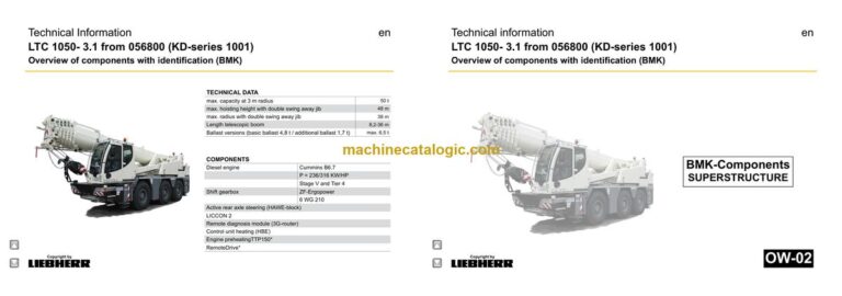
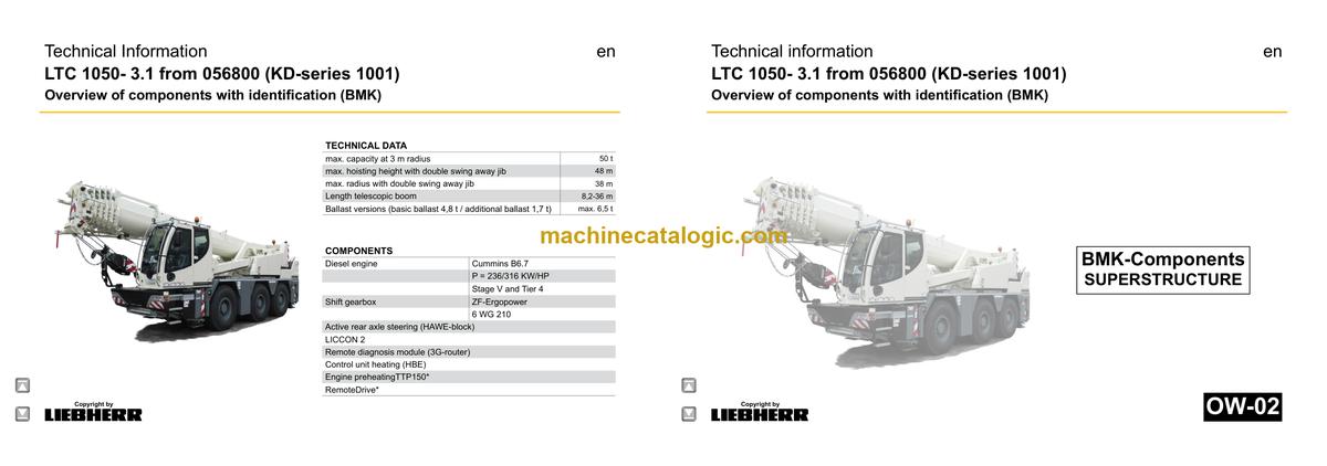
Model: LTC 1050-3.1 Compact Crane
Components: Carrier + Superstructure
Serial No: SN 056849
Date: 2023
Type of Document: Technical Information & BMK Components Manual
$ 80
The Liebherr LTC 1050-3.1 Compact Crane spends its life threading into tight sites, doing lifts where you don’t have room for a full-size all-terrain. When something faults or a sensor goes flaky, the first people reaching for the BMK are your workshop and field techs trying to match an error or wiring symbol to a real box on the machine. Component identification matters because every extra hour hunting for “where the hell is K15?” is an hour the crane isn’t earning and your schedule is slipping. This Technical Information & BMK Components Manual for SN 056849 is about layout and naming, not how to fix things.
What this manual helps you do
Who this is for
This suits workshop technicians, field service techs, electrical diagnostic engineers, fleet mechanics and training instructors planning jobs and training time. If you need repair procedures, fault trees, or part numbers to order spares, you want the service manual and parts catalogue instead.
FAQ
Q: Are the diagrams clear and searchable?
A: Yes, this kind of BMK manual is typically supplied as a readable PDF where you can zoom diagrams and search for component IDs.
Q: Does it cover both carrier and superstructure?
A: Yes, this product combines BMK information for the carrier and the superstructure into one manual.
Q: Does it tie into other Liebherr manuals?
A: Yes, the BMK component identification is meant to be used alongside Liebherr wiring diagrams, hydraulic schematics, service manuals and parts catalogues.
Bottom line: If your main pain is “where is this component on the crane?” this is exactly what you need; if you’re after how to repair or which part to order, it’s not.
Chassis:…………………………………………………………………………………. 5
View from front, lighting and mirror……………………………………………… 5
View rear, lighting……………………………………………………………………… 6
Side view left, illumination………………………………………………………….. 7
Side view right, illumination……………………………………………………….. 8
Warning signal sensors, external start point, plug combination-box…. 9
Electric:………………………………………………………………………………… 10
Battery, main fuse box…………………………………………………………….. 10
CAN – Terminal resistor……………………………………………………………..11
Switch cabinet chassis:………………………………………………………… 12
Fuses……………………………………………………………………………………. 12
I/O- modules, BTB, control unit…………………………………………………. 13
Relays…………………………………………………………………………………… 14
Resistors, clamp strip……………………………………………………………… 15
Emergency operation- and diagnosis plug, telemetry…………………… 16
Plug connections……………………………………………………………………. 17
► Pneumatic system:……………………………………………………………….. 18
Compressor and dryer…………………………………………………………….. 18
Pressure sensors and valves brake system……………………………….. 19
ABV activation valve……………………………………………………………….. 20
Relay- and overload protection valve………………………………………… 21
Adjustment- and relay valve…………………………………………………….. 21
Air reservoir mounting……………………………………………………………… 22
Valve block aux. consumers…………………………………………………….. 23
Driving with radio remote control* (RemoteDrive)……………………….. 24
► Brake system:………………………………………………………………………. 25
Overview – monitoring brake pad………………………………………………. 25
Brake pad monitoring indicator…………………………………………………. 26
► Drive train:……………………………………………………………………………. 27
Overview, shifting conditions……………………………………………………. 27
► Diesel engine Cummins B6.7 , 236 kW (316 HP):…………………….. 28
Installation overview……………………………………………………………….. 28
Type plate on engine………………………………………………………………. 29
Overview fan side…………………………………………………………………… 30
Overview injection side……………………………………………………………. 31
Overview exhaust side…………………………………………………………….. 32
Top view………………………………………………………………………………… 33
Overview fly-wheel side…………………………………………………………… 34
Heating flange………………………………………………………………………… 34
Engine Control Module ECM …………………………………………………… 35
Fuel scheme ( high- and low pressure)……………………………………… 36
Common-Rail-System …………………………………………………………….. 37
Injectors………………………………………………………………………………… 38
Air-sensors…………………………………………………………………………….. 39
Copyright by
liebherr
LWE – Customer Service – Documentation
Author: lweegm0 / Issue: 17.08.2023
LTC 1050-3.1 from 056800 (KD-series 1001) UW-02 • BMK – Component overview 2 of 90
Speed sensors……………………………………………………………………….. 40
Cooling agent…………………………………………………………………………. 41
Oil circuit……………………………………………………………………………….. 42
Exhaust gas turbo charger……………………………………………………….. 43
Exhaust aftertreatment system:…………………………………………….. 44
Overview……………………………………………………………………………….. 44
Exhaust gas system – module overview…………………………………….. 45
Exhaust gas system – sensor technology…………………………………… 46
AdBlue-pump module……………………………………………………………… 47
AdBlue tank and fuel tank gauge unit ……………………………………….. 48
AdBlue tank and hose heating………………………………………………….. 49
Dosing unit AdBlue…………………………………………………………………. 50
Fuel system:…………………………………………………………………………. 51
Fuel tank and fuel filter……………………………………………………………. 51
Cooling system:……………………………………………………………………. 52
Installation overview cooler………………………………………………………. 52
Air filter system:…………………………………………………………………… 53
Air filter, pressure sensor…………………………………………………………. 53
► Power shift gearbox:…………………………………………………………….. 54
ZF 6 WG 210- Overview………………………………………………………….. 54
ZF 6 WG 210 – Transmitters and sensors…………………………………… 55
► Hydraulic:…………………………………………………………………………….. 57
Hydraulic pumps steering, fan………………………………………………….. 57
Hydraulic pumps crane hydraulic, emergency steering………………… 58
Hydraulic pump on axle 3………………………………………………………… 59
Crane hydraulic “ON”………………………………………………………………. 60
Oil tank………………………………………………………………………………….. 61
► Axles with components:……………………………………………………….. 62
ABV – inductive sensors…………………………………………………………… 62
Transversal differential locks……………………………………………………. 63
► Steering:………………………………………………………………………………. 64
Steering gear, steering circuit control………………………………………… 64
Steering decoupling………………………………………………………………… 65
Steering- and centering cylinder ………………………………………………. 66
► Active rear axle steering……………………………………………………….. 67
Centering cylinder, emergency supply……………………………………….. 67
CAN-Valve (HAWE)………………………………………………………………… 68
Control block and pressure filter……………………………………………….. 69
Control block, flow rate indicator, check valve…………………………….. 70
Monitoring centering circuit………………………………………………………. 71
Angle sensor………………………………………………………………………….. 72
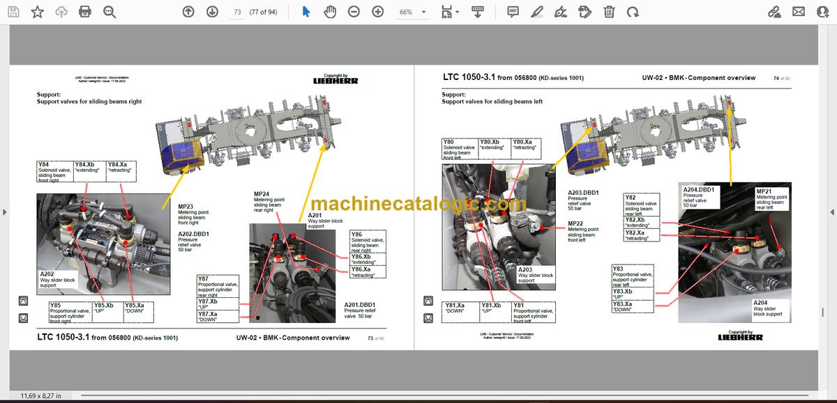
Support valves for sliding beams right……………………………………….. 73
Support valves for sliding beams left…………………………………………. 74
► Support:……………………………………………………………………………….. 75
Inclination sensor …………………………………………………………………… 75
Sliding beam- hydraulic…………………………………………………………… 75
Sliding beam monitoring with rope length sensor………………………… 76
Monitoring support pressure with pressure sensor………………………. 77
► Axle suspension:………………………………………………………………….. 78
Axle suspensions valve, oil supply……………………………………………. 78
Valve block axle suspension right……………………………………………… 79
Valve block axle suspension left……………………………………………….. 80
Axle compensation axle 2………………………………………………………… 81
Level sensor axle suspension…………………………………………………… 82
► Special equipment:……………………………………………………………….. 83
Eddy current brake*………………………………………………………………… 83
Back-up camera*……………………………………………………………………. 84
Air-conditioner………………………………………………………………………… 85
Engine preheatingTTP150*……………………………………………………… 86
► Index……………………………………………………………………………………. 87
► Haftungsbegrenzung / Disclaimer………………………………………….. 90
Superstructure general:………………………………………………………..3
Lighting slewing platform…………………………………………………………3
Lighting boom………………………………………………………………………..4
LMB – warning device (EN 13000)…………………………………………….5
Immobiliser*…………………………………………………………………………..6
Central greasing device…………………………………………………………..7
Ballast – overview……………………………………………………………………8
Ballast – electrically ballast monitoring……………………………………….9
Boom direction……………………………………………………………………..10
► Crane cabin:……………………………………………………………………….11
Heating – additional heating Thermo Pro 90…………………………….. 11
Heating – heating air conditioning……………………………………………12
Heating – activation, temperature sensors………………………………..13
Screen washer unit, platform cab, steering angle………………………14
Interior furnishing………………………………………………………………….15
Electric………………………………………………………………………………..16
Door contact switch………………………………………………………………17
Pneumatic – brake valve………………………………………………………..17
Controls crane cab:…………………………………………………………….18
Control elements (chassis operation)………………………………………18
Tachograph (chassis operation)………………………………………………19
Liccon – monitor, pedals, ethernet……………………………………………20
Joystick, LSB-TE1 right ………………………………………………………..21
Joystick, LSB-TE2 left……………………………………………………………22
Operation- and control unit…………………………………………………….23
BTB, remote control module – BTT………………………………………….24
Switch cabinet crane cabin:………………………………………………..25
Basis assembly – fuses, remote diagnosis………………………………..25
Basis assembly – relay, data logger…………………………………………26
► Switch cabinet slewing platform:…………………………………………27
Tilting frame – fuses………………………………………………………………27
Relay, resistor modules………………………………………………………….28
LSB-board, UEA / EA-module, resistors emergency operation……29
EMERGENCY OPERATION – XNOT-plug………………………………..30
► Pneumatic system:……………………………………………………………..31
Locking slewing platform……………………………………………………….31
► Cab arm:…………………………………………………………………………….32
Cab arm lock………………………………………………………………………..32
Monitoring cab arm locking – sensor………………………………………..33
Cab arm locking – sensors……………………………………………………..34
Cab arm luffing – sensors……………………………………………………….35
Hydraulic – activation, telescoping cylinder……………………………….36
Hydraulic – telescoping cylinder………………………………………………37
Hydraulic – luffing cylinder……………………………………………………..38
Copyright by
liebherr
LWE – Customer Service – Documentation
Author: lweegm0 / Issue: 16.06.2020
LTC 1050-3.1 from 056800 (KD-series 1001) OW-02 • BMK – Component overview 2 of 62
* = Customer‘s spec.
Note:
All stated pressures meet the values values of July 2016!
Cab arm height adjustable*:………………………………………………..39
Cab – electric………………………………………………………………………..39
Telescope arm – electric…………………………………………………………39
Cab arm – activation – hydraulic………………………………………………40
Cab arm luffing – hydraulic and sensors…………………………………..41
Emergency lowering cab – hydraulic………………………………………..42
► Crane hydraulic (chassis):…………………………………………………..43
Hydraulic pumps crane hydraulic, emergency steering………………43
Crane hydraulic “ON” ……………………………………………………………44
Crane hydraulic:…………………………………………………………………45
Overview hydraulic components……………………………………………..45
Main control block…………………………………………………………………46
Main control block – hydraulic, pressure sensor………………………..47
Slewing gear – activation, brake………………………………………………48
Temperature sensor, pretension valve……………………………………..49
Luffing cylinder, “boom steep”…………………………………………………50
Main hoist gear…………………………………………………………………….51
Auxiliary hoist gear*………………………………………………………………52
► Telescoping boom:……………………………………………………………..53
Base section………………………………………………………………………..53
Boom head………………………………………………………………………….54
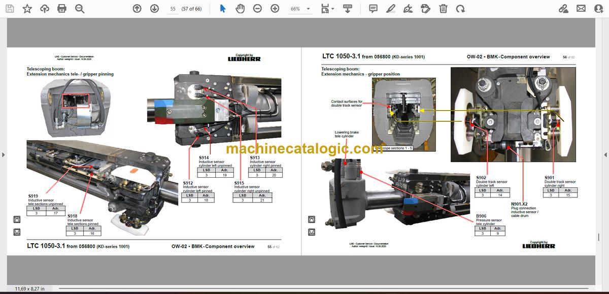
Extension mechanics tele- / gripper pinning……………………………..55
Extension mechanics – gripper position……………………………………56
Tele- / gripper pinning, emergency operation……………………………57
► Special equipment:……………………………………………………………..58
Swing-away jib*……………………………………………………………………58
Back-up camera*, camera winches*………………………………………..59
Emergency control crane hydraulic*………………………………………..60
► Index………………………………………………………………………………….61


