Format: PDF (Printable Document)
File Language: English
File Pages: 274
File Size: 65.67 MB (Speed Download Link)
Brand: Liebherr
Model: LTM 1350-6.1 Mobile Crane
Components: Carrier + Superstructure
Serial No: SN 072466
Date: 2023
Type of Document: Technical Information & BMK Components Manual
$ 80
The Liebherr LTM 1350-6.1 is the kind of crane that earns its keep on big lifts where downtime gets expensive fast. When you’re fault-finding on site with limited tools and time, the BMK (Bauteilkennzeichnung) is what techs grab to turn a schematic ID into a real-world component they can actually touch. The Technical Information & BMK Components Manual for Liebherr LTM 1350-6.1 Mobile Crane provides component identification diagrams, reference designators, and visual outlines used by technicians cross‑referencing wiring or hydraulic schematics to physical parts on the crane. This specific BMK for SN 072466 is about knowing where everything is on both carrier and superstructure, not how to repair it.
What this manual helps you do
Who this is for
This is aimed at workshop technicians, field service techs, electrical diagnostic engineers, fleet mechanics, and training instructors who already have or use other Liebherr manuals. If you need repair procedures, torque values, or part numbers, you want the service manual and parts catalogue instead, not this BMK.
FAQ
Q: Is the PDF clear and searchable?
A: Yes, this kind of BMK manual is normally provided as a readable PDF with clear diagrams you can zoom on a laptop or tablet.
Q: Does it cover both carrier and superstructure?
A: Yes, it combines BMK component identification for the carrier (chassis/undercarriage) and the superstructure (upper crane).
Q: Does it work with my other Liebherr manuals?
A: Yes, it’s meant to be used alongside wiring diagrams, hydraulic schematics, service manuals, and parts catalogues by matching reference designators.
Bottom line: If your main problem is “I see K15 on the diagram, but where is it on this LTM 1350-6.1?”, this is exactly the document you need. If you’re after how-to repair steps or parts ordering, this is the wrong book.
Table of contents
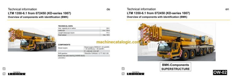
Technical information
LTM 1350-6.1 from 072450 (KD-series 1007)
Overview of components with identification (BMK)
de
► Chassis:……………………………………………………………………………….7
Lighting front and mirrors…………………………………………………………7
Lighting rear…………………………………………………………………………..8
Side marker lights right……………………………………………………………9
Side marker lights left……………………………………………………………10
Sockets, warning signal sensor……………………………………………… 11
Doors and windows, interior lighting………………………………………..12
Driver cab……………………………………………………………………………13
Ventilation and heat exchanger screen wiper and washer………….13
Ventilation and heat exchanger………………………………………………14
Control elements…………………………………………………………………..15
Bluetooth basic unit – BTB……………………………………………………..16
Bluetooth terminal – BTT………………………………………………………..16
Control elements centre console…………………………………………….17
Centre console – I/O- modules, BTB………………………………………..18
Centre console – batteries, battery main switch,
Fuses battery box…………………………………………………………………19
Centre console – fuses…………………………………………………………..20
Centre console – relay……………………………………………………………21
Centre console – voltage converter, heating flange –
control, component carrier……………………………………………………..22
Centre console – components…………………………………………………23
Cntrol unit converter shift clutch/Intarder/ABV…………………………..23
Centre console – fan, EMERGENCY STOP………………………………24
Centre console – diagnosis plug……………………………………………..25
► Pneumatic system:……………………………………………………………..26
Pressure reservoir,………………………………………………………………..27
Trailer control valve*……………………………………………………………..27
Pneumatic valves in the driver cab………………………………………….28
Brake relay valves / overload protection valve………………………….29
Filter and overflow valve in circuit IV A…………………………………….30
Measuring points compressed air circuits…………………………………30
Pressure sensor and pressure switch for axle suspension
and brake system…………………………………………………………………31
Solenoid valve for auxiliary users……………………………………………32
Overview disk brake system…………………………………………………..33
Overview brake pad monitoring………………………………………………34
Brake pad monitoring indicator……………………………………………….35
ABV – regulating valves…………………………………………………………36
ABV – wheel speed sensors……………………………………………………37
► Drive assembly:………………………………………………………………….38
Installation overview complete unit …………………………………………38
View from right……………………………………………………………………..39
View from left……………………………………………………………………….40
Copyright by
liebherr
LWE – Customer Service – Documentation
Author: lweeng1 / Issue: 7/4/2019
LTM 1350-6.1 from 072450 (KD-series 1007) UW-02 • BMK – Component overview 4 of 126
► Diesel engine D9508 A7 -03 (eAGR) / -04 (SCRonly) / -05 (SCRF)…41
Overview V-area…………………………………………………………………..41
Engine control unit………………………………………………………………..42
Fuel-system-overview……………………………………………………………43
Injectors LCR-I S2………………………………………………………………..44
Fuel low pressure sensors……………………………………………………..45
Fuel-pumps………………………………………………………………………….46
Charge air preheating and -sensors………………………………………..47
Exhaust gas turbo charger and wastegate……………………………….48
Coolant- temperature sensor………………………………………………….49
Overview fly-wheel side…………………………………………………………50
Speed-and camshaft sensor…………………………………………………..51
Starter and generator…………………………………………………………….52
Overview fan side…………………………………………………………………53
LIEBHERR-oil module with oil pressure sensor………………………..54
Oil level and oil temperature sensor,
sensor ambient temperature…………………………………………………..55
Exhaust gas flap…………………………………………………………………..56
► Only Powerband H-engines………………………………………………..57
External exhaust gas return eAGR………………………………………….57
Intercooler temperature sensor……………………………………………….58
► Exhaust gas system……………………………………………………………59
Exhaust after treatment “SCRonly”………………………………………….59
Overview……………………………………………………………………………..59
AdBlue-injector and upstream-sensors…………………………………….60
Downstream sensors…………………………………………………………….61
Exhaust after treatment “SCRF”……………………………………………..62
Overview……………………………………………………………………………..62
AdBlue-injector and upstream-sensors…………………………………….63
Downstream sensors…………………………………………………………….64
Exhaust after treatment SCRonly / SCRF ……………………………….65
Urea tank and tank sensor……………………………………………………..65
Pump module and AdBlue-lines………………………………………………66
► Air filter unit at diesel engine D9508 A7-05 and
Power Band H engine………………………………………………………….67
► Diesel fuel device, prefilter unit and tank……………………………..68
► Cooling system…………………………………………………………………..69
Overview……………………………………………………………………………..69
Fan drive,…………………………………………………………………………….70
Pretension centering cylinder…………………………………………………70
► TRAXON TORQUE 12 TT 3021 SO………………………………………..71
Overview of components……………………………………………………….71
Intarder……………………………………………………………………………….74
► Hydraulic supply…………………………………………………………………75
Overview hydraulic pumps……………………………………………………..75
Support and axle suspension…………………………………………………76
Pressure stages……………………………………………………………………77
Temperature sensor hydraulic oil, hydraulic oil tank…………………..78
► Drive train…………………………………………………………………………..79
Overview shifting conditions…………………………………………………..79
Distribution gearbox Kessler W3751 PTO (one stage)……………….80
Transverse differential lock axle 1, axle 3…………………………………81
Transversal differential lock axle 4, axle 5………………………………..82
Longitudinal differential lock distribution gearbox and axle 3,
activation* axle 5…………………………………………………………………..83
► Steering:…………………………………………………………………………….84
Steering ZF-SERVOCOM, deficiency monitoring………………………84
Oil supply steering circuit 1, deficiency monitoring…………………….85
Oil supply steering circuit 2…………………………………………………….86
► Active rear axle steering……………………………………………………..87
Flow and pressure monitoring………………………………………………..87
CAN-valves axle 3 and 4 (HAWE)…………………………………………..88
Control block axle 3 and 4……………………………………………………..89
CAN-valve axle 5 and 6 (HAWE)…………………………………………….90
Control block axle 5 and 6……………………………………………………..91
Angle sensor………………………………………………………………………..92
Steering- and centering cylinder, safety valves…………………………93
► Support:……………………………………………………………………………..94
Level sensor………………………………………………………………………..94
Support valves – right…………………………………………………………….95
Support valves – left………………………………………………………………96
Sliding beam sliding beam……………………………………………………..97
Support cylinder……………………………………………………………………99
Vario Base………………………………………………………………………….100
Sliding beam monitoring………………………………………………………101
► Axle suspension:………………………………………………………………102
Level sensor- axle suspension……………………………………………..102
Control valve – blocked / sprung……………………………………………103
Valve block – axle suspension right………………………………………..104
Valve block – axle suspension left………………………………………….105
Axle suspensions cylinder……………………………………………………106
► Special equipment:……………………………………………………………107
Eddy currant brake Telma Focal 2200*…………………………………..107
Air-conditioner…………………………………………………………………….108
External power supply, 24 V…………………………………………………109
Socket 110 / 230 V………………………………………………………………109
Back-up camera………………………………………………………………….109
Additional heating Thermo Pro 90………………………………………… 110
Engine preheating Airtop EVO 5500 D………………………………….. 111
Thermo S 230……………………………………………………………………. 111
Cooling water preheating…………………………………………………….. 112
External power supply………………………………………………………… 113
Battery charger………………………………………………………………….. 114
Switch over bladder accumulator right…………………………………… 115
Switch over bladder accumulator left…………………………………….. 116
Brake force reduction axle 1 and 2……………………………………….. 117
Brake force reduction axles 3 to 6………………………………………… 118
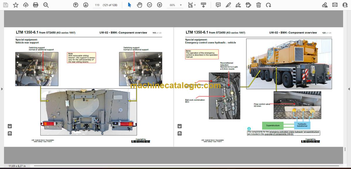
Vehicle rear support……………………………………………………………. 119
Emergency control crane hydraulic – vehicle…………………………..120
► Index………………………………………………………………………………..121
► Haftungsbegrenzung / Disclaimer………………………………………125
Table of contents
Technical information
LTM 1350-6.1 from 072450 (KD-series 1007)
Overview of components with identification (BMK)
en
► Crane cabin:…………………………………………………………………………………….. 5
Control stand…………………………………………………………………………………… 5
LICCON-monitor, pedals……………………………………………………………………..5
Active joystick (AMS1), keyboard unit (LSB TE1) right……………………………. 6
Active joystick (AMS2), keyboard unit (LSB TE2) left……………………………… 7
BKE (operation and control unit)…………………………………………………………..8
Control elements side console……………………………………………………………..9
Camera monitoring (basic set up)……………………………………………………….10
Cab installation………………………………………………………………………………. 11
Radio, interior illumination, driver seat………………………………………………… 11
Wiper motor, washer pump………………………………………………………………..12
Heating – activation, temperature sensors…………………………………………….13
Heating…………………………………………………………………………………………… 14
Heating/additional heating………………………………………………………………….15
Additional heating Thermo Pro 90……………………………………………………….16
Air condition*…………………………………………………………………………………… 17
► Superstructure general:…………………………………………………………………..19
Lights and sensor……………………………………………………………………………..19
Superstructure general:……………………………………………………………………..20
Lights………………………………………………………………………………………………20
LMB – warning device EN 13000…………………………………………………………21
Platform cab……………………………………………………………………………………. 22
Switch cabinet crane cabin:…………………………………………………………….23
Fuses and plug connections……………………………………………………………….23
Data logger 2, remote diagnostics……………………………………………………….24
Diagnosis plug…………………………………………………………………………………. 25
Ethernet switch / diagnosis plug diesel engine………………………………………26
Relays, resistor modules……………………………………………………………………27
► Crane electric:………………………………………………………………………………..28
Battery box……………………………………………………………………………………… 28
Switch cabinet slewing platform:…………………………………………………….29
Overview UEA modules……………………………………………………………………..29
Overview BTB…………………………………………………………………………………. 30
Fuses……………………………………………………………………………………………… 31
Current sources, plug connection………………………………………………………..32
Relay – left side…………………………………………………………………………………33
Fan, relay – right side, earth distribution……………………………………………….34
Emergency operation XNOT-plug……………………………………………………….35
Central greasing device……………………………………………………………………..36
► Drive assembly:………………………………………………………………………………38
Diesel engine D944 A7 -03 (eAGR) / -04 (SCRonly) / -05 (SCRF)………… 38
Overview drive assembly…………………………………………………………………..38
Engine control unit…………………………………………………………………………….39
Overview injection side………………………………………………………………………40
Fuel pumps……………………………………………………………………………………… 41
Fuel low pressure sensors…………………………………………………………………42
Liebherr Daisy-Chain diesel injection system………………………………………..43
Injectors LCR-I S2…………………………………………………………………………….44
Type plates:…………………………………………………………………………………….. 44
Overview exhaust side………………………………………………………………………45
Charge air sensors and -preheating…………………………………………………….46
Copyright by
Liebherr
LWE – Customer Service – Documentation
Author: lweeng1 / Issue: 7/4/2019
LTM 1350-6.1 from 072450 (KD-series 1007) OW-02 • BMK – Component overview 2 of 141
Exhaust gas flap……………………………………………………………………………….47
Exhaust gas turbo charger with wastegate…………………………………………..48
Overview flywheel side and generator…………………………………………………49
Speed sensors…………………………………………………………………………………50
Overview fan side……………………………………………………………………………..51
Coolant, temperature sensor coolant…………………………………………………..52
Oil circuit…………………………………………………………………………………………. 53
Terminal resistor CAN-LIDEC (ECU-CAN2)………………………………………….54
Terminal resistor engine-CAN (ECU-CAN2)………………………………………….55
Diesel engine D944 A7 – 04 (SCRonly) Power Band H-engine…………… 56
Exhaust after treatment ambient air…………………………………………………….56
Diesel engine D944 A7 – 03 / – 05………………………………………………………56
Air filter system – air filter-vacuum……………………………………………………….56
Diesel engine D944 A7 -03 (eAGR) /- 04 (SCRonly) Power Band H-engine..57
External exhaust gas return eAGR………………………………………………………57
Intercooler temperature sensor…………………………………………………………..58
Diesel engine D944 A7 – 03 / – 05………………………………………………………59
Air filter system, air flap in suction air *………………………………………………..59
► Exhaust after treatment SCR:………………………………………………………….60
Urea tank and tank sensor…………………………………………………………………60
Pump module and AdBlue-lines………………………………………………………….61
► Exhaust gas system………………………………………………………………………..62
Exhaust after treatment -04 (SCRonly)……………………………………………..62
Overview exhaust gas system…………………………………………………………….62
Control unit NOx-sensor, upstream-sensors / downstream sensors /
NH3 sensor, AdBlue-injector………………………………………………………………63
Exhaust after treatment -05 (SCRF)………………………………………………….64
Overview exhaust gas system…………………………………………………………….64
Exhaust after treatment -05 (SCRF)…………………………………………………….65
Control unit NOx-sensor, upstream-sensors / downstream sensors /
NH3 sensor, AdBlue-injector………………………………………………………………65
► Cooling system:……………………………………………………………………………..66
Cooler – fan drive………………………………………………………………………………66
Coolant level sensor………………………………………………………………………….67
Fuel delivery……………………………………………………………………………………. 68
Fuel prefilter unit……………………………………………………………………………….69
Fuel tank and tank sensor………………………………………………………………….70
► Pneumatic system:………………………………………………………………………….71
Compressor, compressed air reservoir………………………………………………..71
Air dryer heating……………………………………………………………………………….72
► Crane hydraulic:……………………………………………………………………………..73
pump distributor gear………………………………………………………………………..73
Hydraulic oil tank………………………………………………………………………………74
Overview hydraulic pumps…………………………………………………………………75
Pressure sensors, metering points………………………………………………………76
Supply pressure……………………………………………………………………………….77
Oil cooler and temperature sensor hydraulic oil …………………………………… 78
Pressure stages……………………………………………………………………………….79
Pressure stages………………………………………………………………………………80
Hydraulic connection for emergency operation……………………………………..80
Slewing gear………………………………………………………………………………….. 81
Oil supply, actuation………………………………………………………………………….81
Incremental sensor……………………………………………………………………………82
Boom direction…………………………………………………………………………………83
Hoist gear………………………………………………………………………………………. 84
Supply and activation………………………………………………………………………..84
Winch 1………………………………………………………………………………………….. 85
Winch 2………………………………………………………………………………………….. 86
Needle adjusting winch (TN adjustment pulley)…………………………………….87
Winch 2* – connections………………………………………………………………………88
Assembly winch………………………………………………………………………………..89
Luffing and telescoping…………………………………………………………………..90
Supply and activation………………………………………………………………………..90
Control block…………………………………………………………………………………… 91
Luffing…………………………………………………………………………………………… 92
Way valve for luffing down and
actuation of first lowering brake (ring area)…………………………………………..92
Lowering brakes, pressure sensor………………………………………………………93
Ballasting………………………………………………………………………………………. 94
Supply and activation………………………………………………………………………..94
Way seat valves……………………………………………………………………………….95
Ballasting cylinder…………………………………………………………………………….96
Ballasting cylinder…………………………………………………………………………….97
Electric ballasting……………………………………………………………………………..98
Hydraulic supply for mounting ballast frame…………………………………………99
Ballst pick-up…………………………………………………………………………………. 100
Auxiliary consumer……………………………………………………………………….101
Valves……………………………………………………………………………………………101
Locking slewing platform………………………………………………………………….102
tilting cab………………………………………………………………………………………. 102
► Telescoping boom:………………………………………………………………………..103
Telematic……………………………………………………………………………………… 103
Position sensor……………………………………………………………………………….103
Tele section pinning, toggle valve………………………………………………………104
Gripper pinning, position sensor………………………………………………………..105
Pressure supply unpinning……………………………………………………………….106
Electric………………………………………………………………………………………… 107
Cable drums and length sensors……………………………………………………….107
Boom head, boom nose…………………………………………………………………..108
Working floodlight, wind gauge…………………………………………………………109
► Additional equipment:………………………………………………………………….. 110
Engine preheating DBW 2016………………………………………………………….. 110
Removable boom – connections……………………………………………………….. 112
Removable boom – pin puller device…………………………………………………. 113
Emergency control crane hydraulic…………………………………………………… 114
Dolly (trailer for boom transport USA)……………………………………………….. 115
Dolly (trailer for boom transport USA)……………………………………………….. 116
Fixed jib TF – overview……………………………………………………………………. 117
TYVEN – Overview…………………………………………………………………………. 118
N-Head section………………………………………………………………………………. 119
H-auxiliary jib…………………………………………………………………………………. 120
Luffing lattice jib TN………………………………………………………………………121
N-assembly unit………………………………………………………………………………121
NA-frame 1……………………………………………………………………………………. 122
NA-Frame 3…………………………………………………………………………………… 123
N-pivot section – flap………………………………………………………………………..124
Fall back protection…………………………………………………………………………125
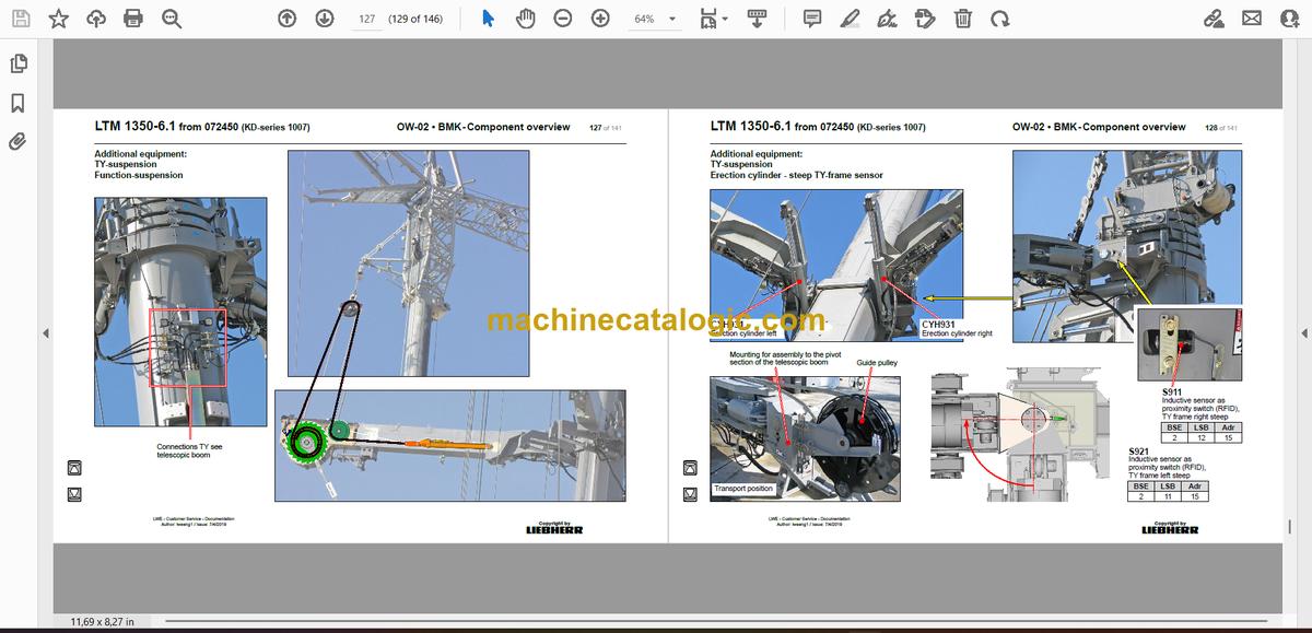
TY-suspension………………………………………………………………………………126
Overview………………………………………………………………………………………. 126
Function-suspension……………………………………………………………………….127
Erection cylinder – steep TY-frame sensor………………………………………….128
Adjustment cylinder – turn sensor………………………………………………………129
Valve block erection- and adjustment cylinder…………………………………….130
Valve block suspension functions………………………………………………………131
Valve block suspension functions………………………………………………………132
suspension winch left and right…………………………………………………………133
Suspension winch – tooth detection……………………………………………………134
Spooling aid – actuation……………………………………………………………………135
Spooling aid – turn sensor………………………………………………………………..136
Tension cylinder………………………………………………………………………………137
► Index……………………………………………………………………………………………. 138


