10% OFF on all manuals and programs. Use code: MCAT10
$ 0
0
$ 0
0

Liebherr MK 140 Mobile Construction Crane Technical Information and BMK Components Manual (Carrier + Superstructure) (SN 077592)

Format: PDF (Printable Document)

File Language: English

File Pages: 241

File Size: 57.51 MB (Speed Download Link)

Brand: Liebherr

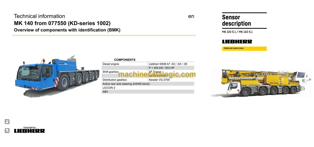
Model: MK 140 Mobile Construction Crane

Components: Carrier + Superstructure

Serial No: SN 077592

Date: 2026

Type of Document: Technical Information & BMK Components Manual

Excellent Rating (4.8) on Trustpilot · Trusted Worldwide
Categories: ,

$ 80

Share:

Liebherr MK 140 Mobile Construction Crane Technical Information and BMK Components Manual (Carrier + Superstructure) (SN 077592)

The Liebherr MK 140 Mobile Construction Crane works hard on tight urban sites, so when it stops, you need to find the faulty bit fast. The Technical Information & BMK Components Manual is what technicians grab when they’ve got a code, a wiring reference, or “that relay behind the cab” and need to know exactly where it lives. Component identification is what saves you hours of guessing, panel pulling, and unnecessary parts swapping. That’s how I keep customer bills down and cranes back on hire.

What this manual helps you do

  • Identify which physical component matches a reference like E1, K15, V12 or X45 in your wiring or hydraulic diagrams.
  • Locate components on the MK 140 carrier and superstructure using visual outlines and layout views.
  • Trace a fault code or schematic symbol to the exact box, sensor, valve, or plug on the machine.
  • Cross-reference Liebherr’s internal component IDs with other factory documents you already have.
  • Pinpoint what Liebherr actually calls a component so you can ask for the right info or order from the correct parts list.

Who this is for

This suits a workshop technician, field service tech, electrical diagnostic engineer, fleet mechanic, or trainer who already has or plans to use wiring diagrams and service info. If you’re after repair procedures, torque specs, or parts numbers, you need a service manual or parts catalogue instead, not this BMK.

FAQ

Q: Is the PDF clear and searchable?

A: Yes, it’s a readable PDF, suitable for zooming in on diagrams and searching text like component IDs.

Q: Does it cover both carrier and superstructure?

A: Yes, this BMK manual covers component identification for both the MK 140 carrier and superstructure in one document.

Q: Does it work with other Liebherr manuals?

A: Yes, the BMK is meant to be used alongside Liebherr wiring diagrams, parts catalogues, and service manuals to tie references to real components.

Bottom line: If your main problem is “Where is Kxx or Vxx on this MK 140, SN 077592?”, this is exactly what you need. If you want how-to-repair steps or part numbers, this isn’t the right book.

📘 Show Index

Table of Contents:

Superstructure — Table of Contents

  • 1 Setting the sensors
    • 1.1 Setting the roller limit switch
    • 1.2 Setting the plunger limit switch to be tamper-proof
    • 1.3 Setting the solenoid switch
  • 2 Checking the sensors
    • 2.1 Checking the roller limit switch
    • 2.2 Checking the plunger limit switch
    • 2.3 Checking the proximity switch
    • 2.4 Checking the solenoid switch
    • 2.5 Checking the connector plug with bayonet lock
  • 3 Switch conditions
  • 4 Overview of sensors
    • 4.1 Sensors on turntable and tower
    • 4.2 Sensors on boom pivot section and boom centre section
    • 4.3 Sensors on boom section 3 and boom section 4
    • 4.4 Sensors on boom extension 1 and boom extension 2
    • 4.5 Sensors according to BMK code (BXXX ascending)
    • 4.6 B4 =S1 Temperature monitor
    • 4.7 B4 =S12 Temperature monitor
    • 4.8 B4 =S13 Temperature monitor
    • 4.9 B101 Wind sensor
    • 4.10 B103 Angle inclination sensor boom centre section
    • 4.11 B105 Wind 2 sensor
    • 4.12 B107 Steel construction temperature sensor
    • 4.13 B108 Load sensor
    • 4.14 B112 Basic ballast present
    • 4.15 B113_1 and 113_2 Additional ballast 1 present
    • 4.16 B114_1 and 114_2 Additional ballast 2 present
    • 4.17 B115_1 and B115_2 Left additional ballast 3 present
    • 4.18 B116_1 and B116_2 Right additional ballast 3 present
    • 4.19 B117_1 Right ballasting equipment extended
    • 4.20 B117_2 Left ballasting equipment extended
    • 4.21 B118_1 Right ballasting equipment retracted
    • 4.22 B118_2 Left ballasting equipment retracted
    • 4.23 B120 Boom lower belt locked
    • 4.24 B121 Boom lower belt unlocked
    • 4.25 B122 Rope safety catch for boom centre section in operating position
    • 4.26 B123 Rope safety catch for boom centre section in assembly position
    • 4.27 B124 Boom section 4 operating position
    • 4.28 B125 Boom section 4 advance shutdown operating position
    • 4.29 B126 Boom section 4 transport position
    • 4.30 B127 Boom section 4 advance shutdown transport position
    • 4.31 B128 Rope safety catch boom section 4 operating position lower belt locked
    • 4.32 B129 Rope safety catch boom section 4 assembly position lower belt unlocked
    • 4.33 B130 Hoist rope pulley in trolley boom operating position
    • 4.34 B131 Hoist rope pulley in jib boom operating position
    • 4.35 B132 Boom tip detection 643
    • 4.36 B133 Hoist rope pulley 643 in jib boom operating position
    • 4.37 B134 Boom tip detection 645
    • 4.38 B135 Hoist rope fixed point monitoring
    • 4.39 B138 Hoist rope pulley 645 in jib boom operating position
    • 4.40 B193 Cab disassembly position
    • 4.41 B200 Slewing gear sensor
    • 4.42 M201 Slewing gear brake 1/2 open
    • 4.43 B211 Chassis turntable locked
    • 4.44 B230 Wind release not active
    • 4.45 B250 Trolley travel gear boom radii sensor
    • 4.46 B251 Trolley travel gear disassembly position
    • 4.47 M251 Trolley travel gear brake open
    • 4.48 B255 Trolley rope tensioning device extended
    • 4.49 B300 Lowering depth sensor
    • 4.50 B307 Load hook disassembly position
    • 4.51 B331 Hoist gear gear shift
    • 4.52 B332 Assembly plant gear shift
    • 4.53 B400 Assembly sensor
    • 4.54 B412 Vertical tower
    • 4.55 B413 Left tower turntable locked
    • 4.56 B414 Left tower turntable unlocked
    • 4.57 B415 Right tower turntable locked
    • 4.58 B416 Right tower turntable unlocked
    • 4.59 B417 Assembly winch slack rope
    • 4.60 B418 Tower is on transport receptacle
    • 4.61 B419 Left tower centre section / lower section locked
    • 4.62 B420 Left tower centre section / lower section unlocked
    • 4.63 B421 Right tower centre section / lower section locked
    • 4.64 B422 Right tower centre section / lower section unlocked
    • 4.65 B424 Tower centre section extended too far
    • 4.66 B423 Tower centre section retracted
    • 4.67 B425 Left tower upper section / centre section locked
    • 4.68 B426 Left tower upper section / centre section unlocked
    • 4.69 B427 Right tower upper section / centre section locked
    • 4.70 B428 Right tower upper section / centre section unlocked
    • 4.71 B429 Tower upper section retracted
    • 4.72 B430 Tower upper section extended too far
    • 4.73 B431 Neck guying caught
    • 4.74 B432 Left boom press extended
    • 4.75 B433 Left boom press retracted
    • 4.76 B434 Right boom press extended
    • 4.77 B435 Right boom press retracted
    • 4.78 B436 Bipod in locking position
    • 4.79 B437 Bipod locked
    • 4.80 B438 Bipod unlocked
    • 4.81 B439 Boom swung in to transport position
    • 4.82 B440 Pre-centring boom upper belt locked
    • 4.83 B441 Boom in transport position
    • 4.84 B445 A-frame in disassembly position
    • 4.85 B450 Auxiliary hoist gear sensor
    • 4.86 M451 Auxiliary hoist gear brake open
    • 4.87 B453 Boom pivot / centre section operating position overrun
    • 4.88 B454 Boom pivot / centre section operating position
    • 4.89 B500 Guy winch sensor
    • 4.90 B501 Transmission temperature sensor
    • 4.91 B504 Guy winch additional brake open
    • 4.92 B507 Boom inclination emergency shutdown
    • 4.93 B600 Overall pressure switch
    • 4.94 B604 Pressure switch for tank line dynamic pressure
    • 4.95 B605 Pressure switch for guy winch additional brake
    • 4.96 B617 Left ballasting pressure switch
    • 4.97 B618 Right ballasting pressure switch
    • 4.98 B620 Pressure switch for tower turntable locking mechanism
    • 4.99 B625 Pressure switch for tower centre section / lower section
    • 4.100 B630 Pressure switch for tower centre section / upper section
    • 4.101 B645 Pressure switch for swivelling boom section 4
    • 4.102 B653 Pressure sensor for tensioning trolley travel rope
    • 4.103 B700 Cab winch value sensor
    • 4.104 M711 / M712 Cab additional brake open
    • 4.105 B731 Cab slack rope at the bottom
    • 4.106 B732 Cab overload
    • 4.107 B733 Cab rope break monitoring

Liebherr Crane

Latest Product

0
    0
    Your Cart
    Your cart is emptyReturn to Shop