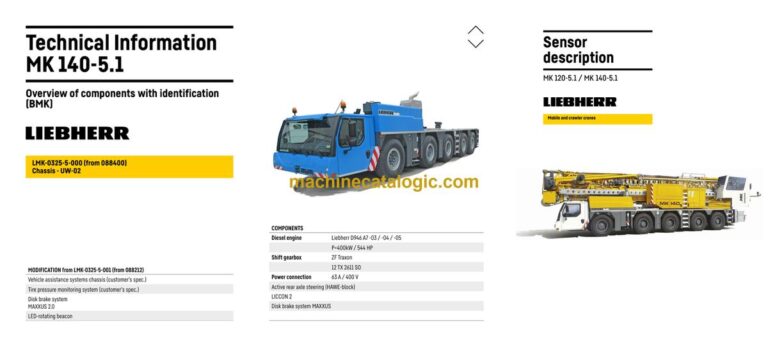
The Liebherr MK 140 Mobile Construction Crane spends its life on tight urban jobs, setting prefab, roofing, and steel where space is ugly and access is worse. When something stops behaving, the first person reaching for a Liebherr BMK component identification manual is usually the tech with a multimeter or laptop in hand. Knowing exactly where “K15” or “X203” sits on the real crane is what lets you fix it fast instead of wasting hours hunting. That’s where this Technical Information & BMK Components Manual for SN 088405 earns its keep and saves you labor time.
What this manual helps you do
- Identify each Liebherr reference designator (E-, K-, V-, X- numbers) and see what physical component it actually is on the MK 140.
- Locate electrical boxes, valves, sensors, control units, and junctions on both the carrier and the superstructure using outline and layout views.
- Trace a fault from a wiring or hydraulic schematic on screen to the exact spot you need to put your hands on the crane.
- Cross-reference component IDs against other Liebherr documents so you know which box or sensor a fault code is really talking about.
- Pinpoint components during training, so new techs learn the MK 140 layout without climbing around blind.
Who this is for
This suits a workshop technician, field service tech, electrical diagnostic engineer, fleet mechanic, or training instructor who already has or plans to use wiring diagrams and service info. If you’re after repair procedures, torque specs, or parts ordering numbers, you’ll want a service manual and parts catalogue instead.
FAQ
Q: Are the diagrams clear and searchable?
A: Yes, this kind of BMK manual is normally supplied as a readable PDF with zoomable, line-drawn component layouts that work well on a laptop in the shop.
Q: Does it cover both the carrier and the crane upper?
A: Yes, this BMK combines carrier and superstructure component identification for the Liebherr MK 140 Mobile Construction Crane in one document.
Q: Does it tie in with other Liebherr manuals?
A: Yes, the BMK is meant to be used alongside wiring diagrams, hydraulic schematics, service manuals, and parts catalogues by matching the same reference designators.
Bottom line: If your main goal is to find and name components on an MK 140 by their Liebherr IDs, this is exactly what you need; if you want how-to repair steps or parts numbers, this isn’t the right book.
📘 Show Index
Table of Contents:
Carrier — Table of Contents
- Table of contents
- Chassis:
- View from front, lighting and mirror
- View from rear
- View from left
- View from right
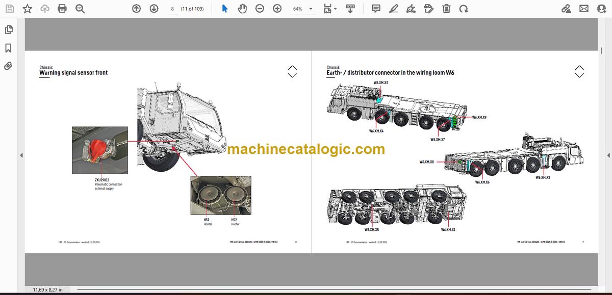
- Warning signal sensor front
- Earth- / distributor connector in the wiring loom W6
- Driver cab:
- Doors and windows, interior lighting
- Ventilation and heat exchanger screen , wiper and – washer
- Ventilation and heat exchanger
- Control elements, seats
- BTB- remote control module BTT
- Control elements centre console up to project number 088211
- Control elements centre console from project number 088212
- Telemetry FMS-interface
- Driver cab – centre console:
- Battery box
- Fuses
- I/O-modules, ECUs
- Relays
- Fan, resistor module
- Voltage converter relay heating flange
- Diagnosis plug, EMERGENCY STOP
- Air-conditioner:
- Overview electrical components
- Pneumatic system:
- Air compressor and air dryer
- Compressed air reservoir
- Pneumatic valves in the driver cab
- Brake relay- / overload protection valve
- Overflow valve, metering points compressed air circuits
- Pressure sensors and pressure switches
- Solenoid valve for auxiliary consumer
- Overview disk brake system
- Disk brake system wear sensor
- Brake pad monitoring display
- ABV – Regulating valves, hill start assist
- ABV wheel speed sensors
- Drive assembly engine D946 A7 -03 (eAGR) / -04 (SCRonly) / -05 (SCRF):
- Drive assembly:
- Engine control unit
- Overview injection side
- Overview exhaust gas side
- Overview flywheel side and generator
- Overview fan side
- Fuel low pressure sensors
- Diesel injection system Daisy-Chain from Liebherr
- Injectors LCR-I S2
- Type plates
- Fuel pumps
- Speed sensors
- Oil circuit
- Ambient temperature diesel engine
- Terminal resistor CAN-LIDEC (ECU-CAN2)
- Terminal resistor engine-CAN (ECU-CAN2)
- Charge air sensors and -preheating
- Exhaust gas flap
- Exhaust gas turbo charger with wastegate
- External exhaust gas return eAGR
- Intercooler temperature sensor
- Exhaust gas aftertreatment
- Urea tank and tank sensor
- Pump module and diesel exhaust fluid-lines
- New pump module from project number 088467
- Exhaust after treatment -04 (SCRonly)
- Overview exhaust gas system
- Diesel exhaust fluid-injector and upstream-sensors
- Downstream sensors
- Exhaust after treatment -05 (SCRF)
- Overview exhaust gas system
- Diesel exhaust fluid-injector and upstream-sensors
- Downstream sensors
- Components diesel engine
- Air filter system
- Diesel fuel system
- Cooling system
- ZF – shift gearbox TraXon 12 TX 2611 SO:
- Gearbox control
- Intarder 3, clutch actuation unit (ConAct)
- Hydraulic
- Overview pressure of the hydraulic pumps
- Temperature sensor hydraulic oil, hydraulic oil tank
- Drive train
- Distribution gearbox Kessler VG 2700 (two stage)
- Road/off-road switchover
- Transversal differential lock axle 2
- Long. and transv. differential lock axle 4 and 5
- Steering
- Steering gear ZF-Servocom, oil supply
- Oil supply
- Active rear axle steering
- Control block
- CAN-valves HAWE
- Pretension centering
- Angle sensor
- Steering- and centering cylinder, safety valves
- Shelf
- Support
- Inclination sensor
- Support valves – right
- Support valves – left
- Extension cylinder sliding beam
- Support cylinder
- Sensors on the support cylinder
- Sliding beam monitoring
- Axle suspension
- Level sensor
- Valve block – right
- Valve block – left
- Control valve – blocked / sprung
- Special equipment
- Additional heating Thermo Pro 90*
- Battery charger*
- Tire pressure monitoring system*
- Assistance system – blind spot – information system (BSIS)*
- Assistance system – moving off information system (MOIS)*
- Assistance system – access for calibration
- Attachment:
- Index
- Technical terms and abbreviations
- Limitation of liability / Disclaimer
Superstructure — Table of Contents
- 1 Setting the sensors
- 1.1 Setting the roller limit switch
- 1.2 Setting the plunger limit switch to be tamper-proof
- 1.3 Setting the solenoid switch
- 2 Checking the sensors
- 2.1 Checking the roller limit switch
- 2.2 Checking the plunger limit switch
- 2.3 Checking the proximity switch
- 2.4 Checking the solenoid switch
- 2.5 Checking the connector plug with bayonet lock
- 3 Switch conditions
- 4 Overview of sensors
- 4.1 Sensors on turntable and tower
- 4.2 Sensors on boom pivot section and boom centre section
- 4.3 Sensors on boom section 3 and boom section 4
- 4.4 Sensors on boom extension 1 and boom extension 2
- 4.5 Sensors according to BMK code (BXXX ascending)
- 4.6 B4 =S1 Temperature monitor
- 4.7 B4 =S12 Temperature monitor
- 4.8 B4 =S13 Temperature monitor
- 4.9 B101 Wind sensor
- 4.10 B103 Angle inclination sensor boom centre section
- 4.11 B105 Wind 2 sensor
- 4.12 B107 Steel construction temperature sensor
- 4.13 B108 Load sensor
- 4.14 B112 Basic ballast present
- 4.15 B113_1 and 113_2 Additional ballast 1 present
- 4.16 B114_1 and 114_2 Additional ballast 2 present
- 4.17 B115_1 and B115_2 Left additional ballast 3 present
- 4.18 B116_1 and B116_2 Right additional ballast 3 present
- 4.19 B117_1 Right ballasting equipment extended
- 4.20 B117_2 Left ballasting equipment extended
- 4.21 B118_1 Right ballasting equipment retracted
- 4.22 B118_2 Left ballasting equipment retracted
- 4.23 B120 Boom lower belt locked
- 4.24 B121 Boom lower belt unlocked
- 4.25 B122 Rope safety catch for boom centre section in operating position
- 4.26 B123 Rope safety catch for boom centre section in assembly position
- 4.27 B124 Boom section 4 operating position
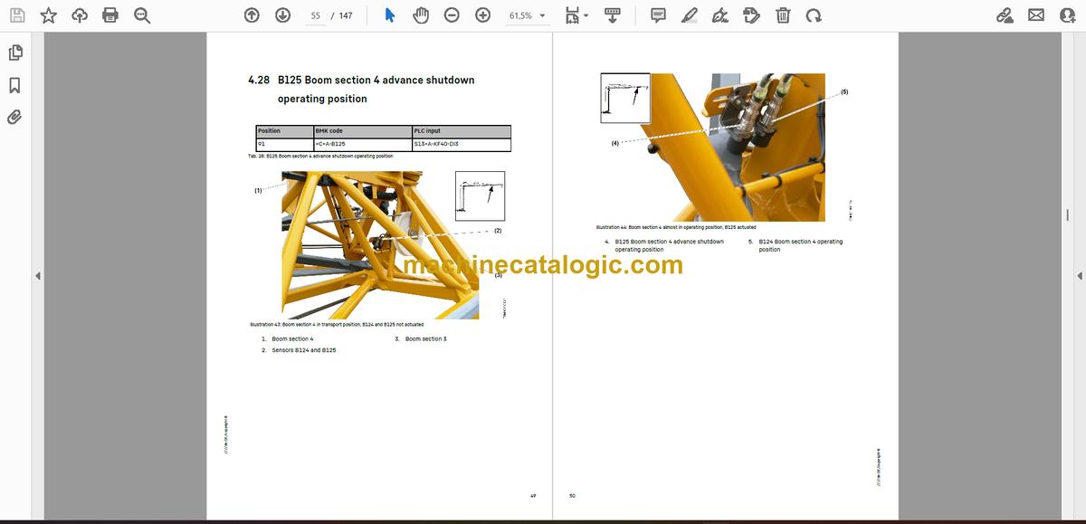
- 4.28 B125 Boom section 4 advance shutdown operating position
- 4.29 B126 Boom section 4 transport position
- 4.30 B127 Boom section 4 advance shutdown transport position
- 4.31 B128 Rope safety catch boom section 4 operating position lower belt locked
- 4.32 B129 Rope safety catch boom section 4 assembly position lower belt unlocked
- 4.33 B130 Hoist rope pulley in trolley boom operating position
- 4.34 B131 Hoist rope pulley in jib boom operating position
- 4.35 B132 Boom tip detection 643
- 4.36 B133 Hoist rope pulley 643 in jib boom operating position
- 4.37 B134 Boom tip detection 645
- 4.38 B135 Hoist rope fixed point monitoring
- 4.39 B138 Hoist rope pulley 645 in jib boom operating position
- 4.40 B193 Cab disassembly position
- 4.41 B200 Slewing gear sensor
- 4.42 M201 Slewing gear brake 1/2 open
- 4.43 B211 Chassis turntable locked
- 4.44 B230 Wind release not active
- 4.45 B250 Trolley travel gear boom radii sensor
- 4.46 B251 Trolley travel gear disassembly position
- 4.47 M251 Trolley travel gear brake open
- 4.48 B255 Trolley rope tensioning device extended
- 4.49 B300 Lowering depth sensor
- 4.50 B307 Load hook disassembly position
- 4.51 B331 Hoist gear gear shift
- 4.52 B332 Assembly plant gear shift
- 4.53 B400 Assembly sensor
- 4.54 B412 Vertical tower
- 4.55 B413 Left tower turntable locked
- 4.56 B414 Left tower turntable unlocked
- 4.57 B415 Right tower turntable locked
- 4.58 B416 Right tower turntable unlocked
- 4.59 B417 Assembly winch slack rope
- 4.60 B418 Tower is on transport receptacle
- 4.61 B419 Left tower centre section / lower section locked
- 4.62 B420 Left tower centre section / lower section unlocked
- 4.63 B421 Right tower centre section / lower section locked
- 4.64 B422 Right tower centre section / lower section unlocked
- 4.65 B424 Tower centre section extended too far
- 4.66 B423 Tower centre section retracted
- 4.67 B425 Left tower upper section / centre section locked
- 4.68 B426 Left tower upper section / centre section unlocked
- 4.69 B427 Right tower upper section / centre section locked
- 4.70 B428 Right tower upper section / centre section unlocked
- 4.71 B429 Tower upper section retracted
- 4.72 B430 Tower upper section extended too far
- 4.73 B431 Neck guying caught
- 4.74 B432 Left boom press extended
- 4.75 B433 Left boom press retracted
- 4.76 B434 Right boom press extended
- 4.77 B435 Right boom press retracted
- 4.78 B436 Bipod in locking position
- 4.79 B437 Bipod locked
- 4.80 B438 Bipod unlocked
- 4.81 B439 Boom swung in to transport position
- 4.82 B440 Pre-centring boom upper belt locked
- 4.83 B441 Boom in transport position
- 4.84 B445 A-frame in disassembly position
- 4.85 B450 Auxiliary hoist gear sensor
- 4.86 M451 Auxiliary hoist gear brake open
- 4.87 B453 Boom pivot / centre section operating position overrun
- 4.88 B454 Boom pivot / centre section operating position
- 4.89 B500 Guy winch sensor
- 4.90 B501 Transmission temperature sensor
- 4.91 B504 Guy winch additional brake open
- 4.92 B507 Boom inclination emergency shutdown
- 4.93 B600 Overall pressure switch
- 4.94 B604 Pressure switch for tank line dynamic pressure
- 4.95 B605 Pressure switch for guy winch additional brake
- 4.96 B617 Left ballasting pressure switch
- 4.97 B618 Right ballasting pressure switch
- 4.98 B620 Pressure switch for tower turntable locking mechanism
- 4.99 B625 Pressure switch for tower centre section / lower section
- 4.100 B630 Pressure switch for tower centre section / upper section
- 4.101 B645 Pressure switch for swivelling boom section 4
- 4.102 B653 Pressure sensor for tensioning trolley travel rope
- 4.103 B700 Cab winch value sensor
- 4.104 M711 / M712 Cab additional brake open
- 4.105 B731 Cab slack rope at the bottom
- 4.106 B732 Cab overload
- 4.107 B733 Cab rope break monitoring
Liebherr Crane


