Format: PDF (Printable Document)
File Language: English
File Pages: 162
File Size: 37.41 MB (Speed Download Link)
Brand: Liebherr
Model: LTM 1500-8.1 Mobile Crane
Components: Carrier + Superstructure
Serial No: SN 073305
Date: 2023
Type of Document: Technical Information & BMK Components Manual
$ 80
Out on a job, the Liebherr LTM 1500-8.1 Mobile Crane earns its keep lifting big, awkward loads where you don’t get a second chance. When something electrical or hydraulic acts up, the techs and electricians reach for the BMK / component identification info, not the operator’s book. Knowing exactly where “K15” or “V23” sits on the machine saves hours of guessing and parts-darts. This Technical Information & BMK Components Manual for SN 073305 is built for that kind of work.
What this manual helps you do
Who this is for
This is for workshop technicians, field service techs, electrical diagnostic engineers, fleet mechanics, and training instructors who already have or plan to use wiring, hydraulic, or service information. If you need step‑by‑step repair procedures, torque specs, or parts ordering numbers, you want the service manual and parts catalogue instead.
FAQ
Q: Are the diagrams clear and searchable in PDF?
A: Yes, this kind of BMK manual is normally supplied as a readable, zoomable PDF with clear component outlines and labels.
Q: Does it cover both the carrier and the superstructure?
A: Yes, it combines BMK information for the carrier and the superstructure of the LTM 1500-8.1 into one product.
Q: Does it work together with other Liebherr documentation?
A: Yes, the BMK reference designators are meant to tie directly into Liebherr wiring diagrams, hydraulic schematics, service manuals, and parts catalogues.
Bottom line: If your goal is to find and identify components on a Liebherr LTM 1500-8.1 by their schematic IDs, this is exactly the manual you need; if you’re after repair steps or part numbers, it isn’t.
Overview of the components with identification (BMK)
Circuit diagram overview:……………………………………………….. 1
Vehicle:………………………………………………………………………….. 4
View from front, lighting and mirrors …………………………………. 4
View from rear, lighting …………………………………………………… 5
Side marker lights, left ……………………………………………………. 6
Side marker lights, right ………………………………………………….. 7
Cab:……………………………………………………………………………….. 8
Doors and windows, interior illumination……………………………. 8
Ventilation and heat exchangers………………………………………. 9
Batteries and main fuse box ………………………………………….. 10
Operator controls …………………………………………………………..11
Digital tachograph ………………………………………………………… 12
Center console:…………………………………………………………… 13
Operator controls …………………………………………………………. 13
I/O modules…………………………………………………………………. 14
Relay………………………………………………………………………….. 15
Fuses …………………………………………………………………………. 16
Instrumentation module, control units ……………………………… 17
Heating flange relay ……………………………………………………… 18
Diagnostic connector ……………………………………………………. 19
Pressurised air system:………………………………………………… 20
Pressure sensors and valves in brake system………………….. 20
Compressor and dryer ………………………………………………….. 21
Auxiliary load valve block………………………………………………. 22
Kundendienst-Technische Dokumentation LWE • lweend2
LTM 1500 – 8.1 from 073 130 UW-02 • BMK- Component overview – –
Drive unit:…………………………………………………………………….. 23
Complete unit……………………………………………………………… 23
Installation view……………………………………………………………. 23
View from right …………………………………………………………….. 24
View from left ………………………………………………………………. 25
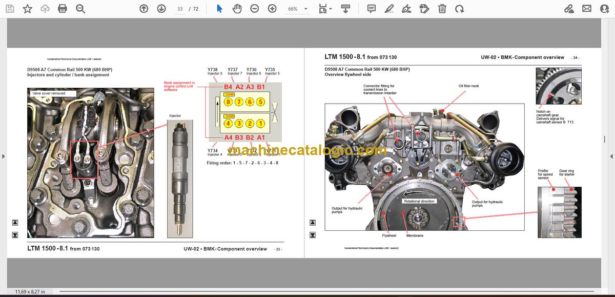
D9508 A7 Common Rail 500 KW (680 BHP)…………………… 26
Overview V area ………………………………………………………….. 26
Engine control unit ECU UP/CR and diagnostic connector … 27
Fuel Service Center ……………………………………………………… 28
Fuel pumps with metering unit ……………………………………….. 29
Rail pressure sensor 1 and 2 …………………………………………. 30
Charge air temperature and charge air pressure sensor ……. 31
Coolant temperature sensor ………………………………………….. 32
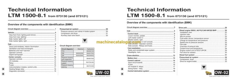
Injectors and cylinder / bank assignment…………………………. 33
Overview flywheel side …………………………………………………. 34
RPM sensor ………………………………………………………………… 35
Water cooled external exhaust return ……………………………… 36
Turbo charger with wastegate………………………………………… 37
Starter and alternator ……………………………………………………. 38
Overview fan side, heater flange ……………………………………. 39
Oil module with oil pressure sensor ………………………………… 40
Air filter vacuum …………………………………………………………… 41
Diesel fuel system: ……………………………………………………… 42
Prefilter unit and tank ……………………………………………………. 42
TC-Tronic HD 12 TC 3040 SO:………………………………………. 43
Component overview ……………………………………………………. 43
Overview of electrics…………………………………………………….. 44
Torque converter ………………………………………………………….. 45
Automatic shift transmission ………………………………………….. 46
Intarder……………………………………………………………………….. 47
Hydraulic pumps: ……………………………………………………….. 48
Overview…………………………………………………………………….. 48
Pressure stages for support and axle suspension …………….. 49
Power train:………………………………………………………………….. 50
Overview…………………………………………………………………….. 50
Transfer gearbox: ……………………………………………………….. 51
Differential locks:………………………………………………………… 52
Eddy current brake Telma FOCAL 3000 24V …………………. 53
Steering:………………………………………………………………………. 54
Steering gear, steering circuit monitoring…………………………. 54
Rear axle steering-steering support …………………………….. 55
Control ……………………………………………………………………….. 55
Independent rear axle steering-“Crab steering”……………. 56
Rear axle release axles 7 and 8 …………………………………….. 56
Raise axles 5 and 6 ……………………………………………………… 57
Raise axles 5 and 6 ……………………………………………………… 58
Steering direction axles 7 and 8……………………………………… 59
Support:……………………………………………………………………….. 60
Supporting valves right …………………………………………………. 60
Supporting valves left……………………………………………………. 61
Inclination sensor, support pressure ……………………………….. 62
Axle suspension:………………………………………………………….. 63
Report axle suspension ………………………………………………… 63
Axle blocking valves……………………………………………………… 64
Actuation for axle compensation and suspended/blocked….. 65
Acknowledgement axle compensation…………………………….. 66
Special equipment:……………………………………………………….. 67
Auxiliary heater and external supply ……………………………. 67
Battery charger …………………………………………………………… 68
Index A to R:…………………………………………………………………. 69
Index S to Y: …………………………………………………………………. 70
Circuit diagram overview:……………………………………………….. 3
Cab:………………………………………………………………………………… 5
Control desk:…………………………………………………………………. 5
Liccon monitor, pedals…………………………………………………….. 5
Left master switch 2………………………………………………………… 6
Master switch, right…………………………………………………………. 7
Operator controls in roof console………………………………………. 8
Side console – Operator controls………………………………………. 9
Side console – Relays and fuses……………………………………… 10
Cab installation:…………………………………………………………….11
Radio and windshield wiper system…………………………………..11
Headlights, horn……………………………………………………………. 12
Crane electrics………………………………………………………………. 13
Battery box:…………………………………………………………………. 13
Control cabinet:…………………………………………………………… 14
Input circuit boards………………………………………………………… 15
Fuses………………………………………………………………………….. 16
I/O module 6, relays………………………………………………………. 17
Swing frame – relay……………………………………………………….. 18
Central lubrication system:………………………………………….. 19
Drive unit:……………………………………………………………………… 20
Diesel engine D936 L A6 PLD 240 kW/322 BHP:…………….. 20
Installation view…………………………………………………………….. 20
Injection side………………………………………………………………… 21
Slip-on pumps………………………………………………………………. 22
Fuel-water sensor, temperature sensor……………………………. 23
Charge air temperature and pressure………………………………. 24
Speed and oil pressure sensors……………………………………… 25
Fan-side………………………………………………………………………. 26
Overview of exhaust side……………………………………………….. 27
Coolant level and temperature………………………………………… 28
Engine control unit LH ECU UP/CR…………………………………. 29
Fan drive for radiator……………………………………………………… 30
Diesel fuel system:………………………………………………………. 31
Pressurised air system:……………………………………………….. 32
Compressor, dryer………………………………………………………… 32
Drive for engine brake……………………………………………………. 33
Kundendienst-Technische Dokumentation LWE • lweend2
LTM 1500 – 8.1 from 073 130 OW-02 • BMK – Component overview – –
Crane hydraulics:………………………………………………………….. 34
Overview hydraulic pumps……………………………………………… 34
Overview hydraulic pump pressure gauges………………………. 35
Pressure stages pump 10………………………………………………. 36
Oil flow pump 10…………………………………………………………… 37
Overview hydraulic components……………………………………… 38
Hydraulic oil radiator and temperature sensor…………………… 39
Slewing gear………………………………………………………………… 40
Control………………………………………………………………………… 40
Coasting and braking…………………………………………………….. 41
Rotary connection, boom direction………………………………….. 42
Hoist gear……………………………………………………………………. 43
Hoist gear 1 – Winch……………………………………………………… 43
Hoist gear 1 – Drive……………………………………………………….. 44
Hoist gear 2* – Winch…………………………………………………….. 45
Hoist gear 2* – Drive………………………………………………………. 46
Hoist gear 3 (needle adjustment winch)* – Winch………………. 47
Hoist gear 3 (needle adjustment winch)* – Drive………………… 48
Assembly winch……………………………………………………………. 49
Luffing gear…………………………………………………………………. 50
Supply for luffing and telescoping……………………………………. 50
Control block for luffing and telescoping…………………………… 51
Pressure gauge luffing cylinder……………………………………….. 52
First lowering brake-luffing cylinder-piston surface…………….. 53
Second lowering brake-luffing cylinder-piston surface………… 54
Directional valves luffing cylinder…………………………………….. 55
ballasting…………………………………………………………………….. 56
Supply…………………………………………………………………………. 56
Control………………………………………………………………………… 57
Auxiliary loads…………………………………………………………….. 58
Turntable lock………………………………………………………………. 58
Turn and tilt cab……………………………………………………………. 59
Telescopic boom:………………………………………………………….. 60
Extension mechanism “Telematics”……………………………… 60
Gripper pinning – Tele-position………………………………………… 60
Gripper pinning…………………………………………………………….. 61
Tele pinning………………………………………………………………….. 62
Telescopic cylinder valves………………………………………………. 63
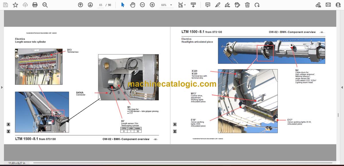
Electrics………………………………………………………………………. 64
Limit switch and angle sensor…………………………………………. 64
Length sensor tele cylinder…………………………………………….. 65
Headlights articulated piece……………………………………………. 66
Special equipment:……………………………………………………….. 67 Circuit diagram overview:
Hydraulically adjustable fixed lattice jib TF…………………… 67
Luffing lattice jib TN…………………………………………………….. 68
N-Assembly unit……………………………………………………………. 68
N-Articulated piece – Flap………………………………………………. 69
NA-frame 3…………………………………………………………………… 70
Safety retainer………………………………………………………………. 71
N-Head piece……………………………………………………………….. 72
Telescope guying – TY3:………………………………………………… 73
Overview 1…………………………………………………………………… 73
Adjustment cylinder – Angle sensor………………………………….. 74
Adjustment cylinder – Directional valves…………………………… 75
Proximity switch – TY3-guy frame erected………………………… 76
Stay rope winch – Pressure gauge, tensioning cylinder………. 77
Stay rope winch – Sensor, latch………………………………………. 78
Stay rope winch – Sensor, tensioning cylinder…………………… 79
Hydraulics – Control block………………………………………………. 80
Spacer* – Spooling aid…………………………………………………… 81
Overviews:……………………………………………………………………. 82
Guying points TY3………………………………………………………… 82
Air conditioning system……………………………………………….. 83
Auxiliary heater……………………………………………………………. 84
Index…………………………………………………………………………….. 86


