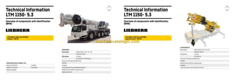
The Liebherr LTM 1150-5.3 Mobile Crane earns its keep on tight job sites where setup time and reliability really matter. When something’s acting up, the first person who’ll grab this BMK component identification manual is usually the electrician or hydraulic tech trying to match a fault or schematic symbol to a real-world part. In a workshop, knowing exactly where “K15” or “V47” sits on the machine can save you an hour of hunting around the carrier or superstructure. That’s what this Technical Information & BMK Components Manual for SN 079383 is built for, not for step‑by‑step repairs.
What this manual helps you do
- Identify which physical component matches a reference like E, K, V, X from your wiring or hydraulic diagrams.
- Locate relays, sensors, valves, junction boxes, and harnesses on the carrier and superstructure using outline and layout views.
- Trace schematic items on the Liebherr LTM 1150-5.3 BMK diagrams to their mounting position on the crane frame, boom, or cab.
- Cross-reference component IDs to other Liebherr documents (wiring diagrams, service info, fault lists) so everyone’s talking about the same part.
- Pinpoint components during training so new techs learn the machine layout without tearing half the crane apart.
Who this is for
This is aimed at workshop technicians, field service techs, electrical diagnostic engineers, fleet mechanics, and training instructors. If you’re after repair procedures, torque specs, or part numbers, you need the service manual and parts catalogue instead.
FAQ
Q: Is the PDF clear and searchable?
A: Yes, this type of BMK manual is normally supplied as a readable PDF where you can zoom in on diagrams and search text labels.
Q: Does it cover both carrier and superstructure?
A: Yes, it combines the BMK layouts for the lower carrier and the upper crane superstructure in one document.
Q: Does it work with other Liebherr manuals?
A: Yes, the whole point is to match BMK IDs to wiring diagrams, service information, and parts catalogues so you can go from fault code to component to part order.
Bottom line: If you need to find and name components on this exact LTM 1150-5.3 (SN 079383), this is the right manual. If you want “how to fix it,” this is not what you need.
📘 Show Index
Table of Contents:
Carrier — Table of Contents
- Table of contents
- Chassis:
- View from front, lighting and mirror
- View rear, lighting
- Vehicle lighting right
- Vehicle lighting left
- Warning signal sensor, air pressure connection / front
- Trailer coupling*, air pressure connection, warning signal sensor / rear
- Plug connection, voltage converter
- Earth- and distributor connector in the wiring loom – W7
- Earth- and distributor connector in the wiring loom – W6
- Control elements
- BTB, remote control module – BTT
- Control elements centre console
- Driver cab:
- Doors and windows, interior lighting
- Screen wiper and – washer
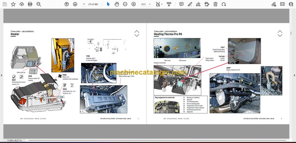
- Heating – ventilation and heat exchanger
- Air-conditioner
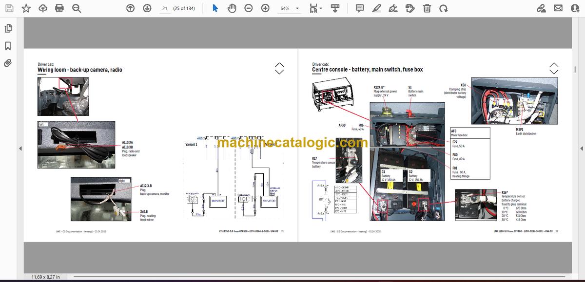
- Wiring loom – back-up camera, radio
- Centre console – battery, main switch, fuse box
- Center console – I/O modules, BTB
- Centre console – fuses
- Centre console – relay
- Centre console – relay
- Centre console – voltage converter, activation heating flange
- Centre console – control unit ABV, components
- Centre console – fan, component carrier, Emergency STOP
- Centre console – diagnosis plug
- Telemetry FMS-interface
- Pneumatic system:
- Air compressor and air dryer
- Compressed air reservoir
- Pneumatic valves in the driver cab
- Brake relay- and overload protection valve
- Filter and overflow valve, measuring points compressed air circuits
- Solenoid valve for auxiliary consumer
- Pressure sensors and pressure switches
- Monitoring parking brake
- Disk brake system:
- Overview – brake system
- Overview – brake pad monitoring
- Brake pad monitoring display
- ABV control valve
- ABV wheel speed sensors
- Hill start assist
- Drive assembly:
- Installation view
- Diesel engine – installation
- Diesel engine D946 A7 -03 (eAGR) 04 (SCR) / -05 (SCRF):
- Engine control unit
- Overview injection side
- Fuel pumps
- Fuel low pressure sensors
- Liebherr diesel injection system Daisy Chain
- Injectors LCR-I S2
- Type plates:
- Overview exhaust gas side
- Charge air sensors and charge air preheating
- Exhaust gas flap
- Exhaust gas turbo charger with wastegate
- Overview flywheel side and generator
- Speed sensors
- Overview fan side
- Coolant, temperature sensor coolant and ambient temperature
- Oil circuit
- Terminal resistor CAN-LIDEC (ECU-CAN2)
- Terminal resistor engine-CAN (ECU-CAN2)
- External exhaust gas return eAGR
- Intercooler temperature sensor
- Exhaust gas system – exhaust after treatment SCRonly:
- Overview
- AdBlue-injector and upstream-sensors
- Downstream sensors
- Overview
- AdBlue-injector and upstream-sensors
- Downstream sensors
- Urea tank and urea tank sensor
- Pump module and AdBlue-lines
- Air filter system:
- Air filter-vacuum, air flap
- Diesel fuel system:
- Cooling system:
- Cooler – fan drive, level sensor
- Automatic shift gearbox to 079365:
- ZF TraXon 12 TX 2611 SO (intarder 3)
- ZF TraXon Intarder 3, clutch actuation unit (ConAct)
- Automatic shift gearbox from 079366:
- ZF TraXon DynamicPerform 12 DX 2611 SO – gearbox control
- ZF TraXon DynamicPerform 12 DX 2611 SO – Intarder
- ZF TraXon DynamicPerform 12 DX 2611 SO – wet starting clutch
- Hydraulic:
- Temperature sensor hydraulic oil, hydraulic oil tank
- Hydraulic pumps – overview
- Fan valve, pretension centering pressure
- Drive train:
- Overview
- Distribution gearbox Kessler VG 2700 (two stage)
- Road-/ offroad gear – switching
- Travel drive / crane drive (PTO) – switching
- Crane drive
- Transverse differential lock axle 1, longitudinal differential lock distribution gear
- Transversal differential lock axle 2, activation axle 1*
- Long. and transv. differential lock axle 4 and 5
- Transverse differential lock axle 5
- Steering:
- Steering from superstructure
- Steering gear ZF-Servocom
- Oil supply steering circuit 1, deficiency monitoring
- Oil supply steering circuit 2
- Active rear axle steering:
- CAN-Valves (HAWE)
- Control block
- Valve block
- Oil filter
- Angle sensor
- Steering- and centering cylinder, safety valves
- Support:
- Inclination sensor
- Support valves – right
- Support valves – left
- Extension cylinder
- Sliding beam monitoring
- Support cylinder
- Monitoring support pressure
- Axle suspension:
- Level sensor- axle suspension
- Valve block – axle suspension right
- Valve block – axle suspension left
- Switch over diaphragm reservoir*
- Special equipment:
- Brake force reduction axle 1 and 2
- Brake force reduction axles 3 to 5
- Eddy currant brake Telma Focal 2200*
- Additional heating – Thermo Pro 90
- Additional heating – Air Top 2000 ST*
- Additional heating – engine pre-heating*
- External power supply
- Back-up camera*
- Battery charger
- Hydraulic emergency control
- Attachment:
- Index
- Limitation of liability / Disclaimer
Liebherr Crane


