Format: PDF (Printable Document)
File Language: English
File Pages: 211
File Size: 34.71 MB (Speed Download Link)
Brand: Liebherr
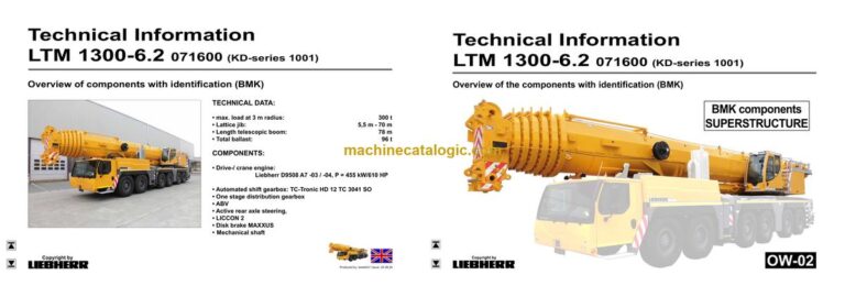
Model: LTM 1300-6.2 Mobile Crane
Components: Carrier + Superstructure
Serial No: SN 071617
Date: 2023
Type of Document: Technical Information & BMK Components Manual
$ 80
The Liebherr LTM 1300-6.2 Mobile Crane is a complex all‑terrain machine, and when you’re fault‑finding on one, knowing where a component sits matters as much as knowing what it does. The Technical Information & BMK Components Manual for SN 071617 is what technicians grab when a wiring diagram says “K15” or “E23” and they need to see that part on the actual crane. This kind of BMK manual usually shows outline views, reference designators, and location diagrams, not how to repair or adjust anything. So if your main problem is “I can’t find this component on the machine,” you’re looking in the right direction.
What this manual helps you do
Who this is for
This is aimed at workshop technicians, field service techs, electrical diagnostic engineers, fleet mechanics, and training instructors who already have or use wiring diagrams and service info. If you need step‑by‑step repair procedures, torque specs, or parts ordering numbers, you want a service manual or parts catalogue instead, not this BMK.
FAQ
Q: Are the diagrams clear and searchable?
A: Yes, these BMK PDFs are normally clean, zoomable layout drawings that you can search by component ID.
Q: Does it cover both carrier and superstructure layouts?
A: Yes, this product combines BMK information for the carrier and the superstructure of the LTM 1300-6.2 into one manual.
Q: Does it tie in with other Liebherr manuals I already have?
A: Yes, the BMK component identification links the reference designators you see in wiring diagrams, service manuals, and parts catalogues to real hardware on the crane.
Bottom line: If your main need is component identification and location on a Liebherr LTM 1300-6.2, this BMK manual is exactly what you need; if you want repair steps or part numbers, it’s not.
Overview of components with identification (BMK)
Produced by: lwedoh3 / Issue: 20.08.24
► Chassis:………………………………………………………………………………………….. 4
Lighting front and mirrors…………………………………………………………………..4
Lighting rear…………………………………………………………………………………….5
Side marker lights right………………………………………………………………………6
Side marker lights left………………………………………………………………………..7
Sockets, warning signal sensor…………………………………………………………..8
► Driver’s cab:…………………………………………………………………………………….. 9
Doors and windows, interior lighting……………………………………………………. 9
Ventilation and heat exchanger…………………………………………………………10
Screen wiper and washer…………………………………………………………………10
Ventilation and heat exchanger………………………………………………………… 11
Control elements…………………………………………………………………………….12
Operation elements new (KD-Series 1002)…………………………………………13
Bluetooth Basic unit – BTB, Bluetooth Terminal – BTT…………………………. 14
Control elements centre console……………………………………………………….15
Centre panel – I/O- modules, BTB…………………………………………………….. 16
Centre panel – batteries, battery main switch, Fuses battery box………….. 17
Centre panel – fuses………………………………………………………………………..18
Centre panel – relay…………………………………………………………………………19
Centre panel – voltage converter, Heating flange control…………………… 20
Centre panel – components, control units…………………………………………… 21
Centre panel – ventilator, component carrier……………………………………….22
EMERGENCY STOP……………………………………………………………………….22
Centre panel – diagnosis plug……………………………………………………………23
► Pneumatic system:………………………………………………………………………….24
Air compressor and air dryer…………………………………………………………….24
Pressurised air reservoir Trailer control valve*…………………………………….25
Pneumatic valves in the driver cab……………………………………………………. 26
Brake relay- / overload protection valve…………………………………………….. 27
Filter and overflow valve in circuit IV A,
Measuring points compressed air circuits………………………………………….. 28
Pressure sensor and pressure switch for axle suspension
and brake system……………………………………………………………………………………..29
Solenoid valves auxiliary consumer………………………………………………….. 30
Overview disk brake system……………………………………………………………..31
Overview brake pad monitoring…………………………………………………………32
Brake pad monitoring indicator………………………………………………………….33
ABV – control valve………………………………………………………………………….34
ABV – wheel speed sensors……………………………………………………………..35
► Drive assembly:………………………………………………………………………………36
Complete unit Installation view………………………………………………………….36
View from right……………………………………………………………………………….37
View from left………………………………………………………………………………….38
Copyright by
liebherr
LTM 1300-6.2 071600 (KD-series 1001) UW-02 • BMK – Component overview 2 of 125
Customer Service-Technical Documentation LWE
Produced by: lwedoh3 / Issue: 20.08.2024
* = Optional
► Diesel engine D9508 A7 stage IV SCR and Power Band H…………………39
Overview V-area……………………………………………………………………………..39
Engine control unit…………………………………………………………………………..40
Fuel system Overview……………………………………………………………………..41
Injectors LCR-I S2…………………………………………………………………………..42
Type plates:……………………………………………………………………………………42
Fuel low pressure sensors……………………………………………………………….43
Fuel pumps…………………………………………………………………………………….44
Coolant- temperature sensor…………………………………………………………….47
Overview fly-wheel side……………………………………………………………………48
Speed-and camshaft sensor…………………………………………………………….49
Starter and generator………………………………………………………………………50
Overview fan side……………………………………………………………………………51
LIEBHERR-oil module with oil pressure sensor…………………………………..52
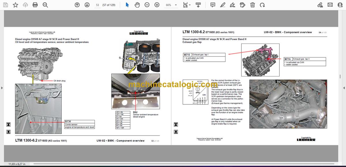
Oil level and oil temperature sensor, sensor ambient temperature………… 53
Exhaust gas flap……………………………………………………………………………..54
Only stage Power Band H-engines
External exhaust gas return eAGR……………………………………………………. 55
Intercooler temperature sensor…………………………………………………………56
► Exhaust gas aftertreatment SCR……………………………………………………..57
Overview exhaust gas system…………………………………………………………..57
Urea tank and tank sensor……………………………………………………………….58
Pump module and AdBlue-lines………………………………………………………..59
AdBlue-injector and upstream-sensors……………………………………………… 60
Downstream sensors……………………………………………………………………….61
Ambient air sensor and exhaust gas flap…………………………………………… 62
► Air filter unit at engine Power Band H………………………………………………63
Air flap in air filter unit*…………………………………………………………………….63
► Diesel fuel device, prefilter unit and tank…………………………………………64
► Cooling system:……………………………………………………………………………..65
Overview……………………………………………………………………………………….65
Fan drive……………………………………………………………………………………….66
► TC-Tronic HD 12 TC 3041 SO:…………………………………………………………67
Overview of components………………………………………………………………….67
Torque converter…………………………………………………………………………….68
Automated shift gearbox………………………………………………………………….69
Intarder………………………………………………………………………………………….70
► Hydraulic supply:……………………………………………………………………………71
Overview hydraulic pumps……………………………………………………………….71
Support and axle suspension……………………………………………………………72
Pressure stages……………………………………………………………………………..73
Temperature sensor hydraulic oil, hydraulic oil tank……………………………..74
► Drive train:…………………………………………………………………………………….. 75
Overview, shifting conditions…………………………………………………………….75
Distribution gearbox Kessler W3751 PTO (one stage)………………………… 76
Switch over travel drive / crane drive (PTO)………………………………………..77
Crane drive…………………………………………………………………………………….78
Crane drive – angle gear box…………………………………………………………….79
Transverse differential lock axle 1, axle 3………………………………………….. 80
Transversal differential lock axle 4, axle 5………………………………………….. 81
Longitudinal differential lock distribution gearbox and axle 3,
activation* axle 5 (drive 12×8)…………………………………………………………..82
► Steering:………………………………………………………………………………………… 83
Steering gear ZF-SERVOCOM, Deficiency monitoring……………………….. 83
Oil supply steering circuit 1, deficiency monitoring……………………………….84
Oil supply steering circuit 2………………………………………………………………85
► Active rear axle steering:…………………………………………………………………86
Flow and pressure monitoring…………………………………………………………..86
CAN-valves axle 3 and 4 (HAWE)…………………………………………………….. 87
Control block axle 3 and 4………………………………………………………………..88
CAN-valve axle 5 and 6 (HAWE)………………………………………………………89
Control block axle 5 and 6………………………………………………………………..90
Angle sensor………………………………………………………………………………….91
Steering- and centering cylinder, safety valves……………………………………9
► Support………………………………………………………………………………………….. 93
Inclination sensor……………………………………………………………………………93
Support valves – right………………………………………………………………………94
Support valves – left…………………………………………………………………………95
Support valve as of project number 071645 (KD-series 1002)……………… 96
Sliding beam sliding beam……………………………………………………………….97
Support cylinder……………………………………………………………………………..99
Support force sensor (AKG)……………………………………………………………100
Supporting force sensor – plug connections………………………………………101
Vario Base with pressure sensor……………………………………………………..102
Sliding beam monitoring…………………………………………………………………103
► Axle suspension:…………………………………………………………………………..104
Level sensor- axle suspension………………………………………………………..104
Control valve – blocked / sprung………………………………………………………105
Valve block – axle suspension right…………………………………………………. 106
Valve block – axle suspension left……………………………………………………107
Axle suspensions cylinder………………………………………………………………108
► Special equipment:……………………………………………………………………….109
Eddy currant brake Telma Focal 2200*……………………………………………. 109
Air condition*……………………………………………………………………………….. 110
External power supply 24 V*, socket 110 / 230 V*………………………………111
Back-up camera*……………………………………………………………………………111
Additional heating Thermo Pro 90*…………………………………………………. 112
Engine preheating* Airtop EVO 5500 D / Thermo S 230…………………….. 113
Cooling water preheating*……………………………………………………………… 114
External power supply*………………………………………………………………….. 115
Battery charger*…………………………………………………………………………… 116
Switch over badder accumulator right*…………………………………………….. 117
Switch over badder accumulator left*………………………………………………. 118
Brake force reduction axle 1 and 2*………………………………………………… 119
Brake force reduction axles 3 to 6 left*…………………………………………….. 120
Support rear of vehicle…………………………………………………………………..121
Emergency control cran hydraulic* – vehicle……………………………………..122
► Index……………………………………………………………………………………………. 123
►►Superstructure, general:……………………………………………… 3
Turntable lighting…………………………………………………………………..3
LMB warning device (EN 13000)…………………………………………….4
Central lubrication system………………………………………………………5
►►Crane operator’s cab:………………………………………………….. 6
Heater – heating / air conditioning device………………………………….6
Heating – Additional heating Thermo Pro 90……………………………..7
Heater – actuation, temperature sensors………………………………….8
Wipers motors, washer pump…………………………………………………9
Interior……………………………………………………………………………….10
Cab pedestal……………………………………………………………………… 11
►►Cab fittings:………………………………………………………………. 12
Liccon monitor, pedals…………………………………………………………12
Master switch, LSB-TE1 right……………………………………………….13
Master switch, LSB-TE2 left………………………………………………….14
Control unit…………………………………………………………………………15
►►Crane operator’s cab control cabinet:………………………… 16
Swing frame – fuses…………………………………………………………….16
UEA’s / BTB’s……………………………………………………………………..17
Swing frame – turntable connector panel………………………………..18
Swing frame – cab connector panel……………………………………….19
Mounting plate – LSB master, diode module……………………………20
Mounting plate – relays…………………………………………………………21
Mounting plate – voltage supply…………………………………………….22
Mounting plate – release relay, ground distribution…………………..23
Cab cabinet air circulation, power converter……………………………24
Data logger II, remote diagnostics…………………………………………25
Diagnostic plugs………………………………………………………………….26
EMERGENCY OPERATION – sockets……………………………………27
►►Crane drive:………………………………………………………………. 28
Mechanical shaft…………………………………………………………………28
Angle transmission………………………………………………………………29
Distribution gearbox…………………………………………………………….30
►►Crane hydraulics:………………………………………………………. 31
Overview of hydraulic pumps………………………………………………..31
Hydraulic oil tank…………………………………………………………………32
Overview of hydraulic components………………………………………..33
Pressure stages………………………………………………………………….34
Supply pressure………………………………………………………………….35
Temperature sensor and oil cooler…………………………………………36
▪▪Slewing gear………………………………………………………………………37
Pump 12…………………………………………………………………………….37
Activation, brake…………………………………………………………………38
Slewing sensor……………………………………………………………………39
*Optional
▪▪Hoist gear………………………………………………………………………….40
Pumps and pressure sensor…………………………………………………40
Winch 1……………………………………………………………………………..41
Winch 2……………………………………………………………………………..42
Winch mounting winch 2………………………………………………………43
TN-adjusting pulley……………………………………………………………..44
Winch 2* – connections………………………………………………………..45
Assembly winch………………………………………………………………….46
▪▪Luffing and telescoping……………………………………………………..47
Pump and pressure sensor…………………………………………………..47
Control block………………………………………………………………………48
Telescopic re-suction
from project no. 071645 on (KD-series 1002)………………………….49
Lowering brake and pressure sensor……………………………………..50
Auxiliary drive luffing……………………………………………………………51
▪▪Auxiliary user…………………………………………………………………….52
Pump…………………………………………………………………………………52
Valve block…………………………………………………………………………53
Ballasting…………………………………………………………………………..54
Superstructure locking, tilting cylinder cab………………………………55
►►Telescopic boom:………………………………………………………. 56
▪▪Electric………………………………………………………………………………56
Heel section……………………………………………………………………….56
Electric………………………………………………………………………………57
▪▪Telematik……………………………………………………………………………58
Position sensor, tele section pinning………………………………………58
Cylinder pinning, toggle valve……………………………………………….59
Emergency operation tele- / cylinder pinning…………………………..60
►►Special equipment:……………………………………………………. 61
Folding jib* / special folding jib* – electric………………………………..61
Folding jib* – hydraulics………………………………………………………..62
Hydr. folding jib* – hose drum………………………………………………..63
Air conditioning system*……………………………………………………….64
Winch camera monitor*………………………………………………………..65
Camera monitoring winches and slewing platform right*…………..66
Immobiliser system*…………………………………………………………….67
Dolly operation*…………………………………………………………………..68
Tele dismounting*………………………………………………………………..69
Crane hydraulics emergency control* – right turntable………………70
Emergency activation crane hydraulics* – superstructure left…….71
▪▪Luffing fly jib*…………………………………………………………………….72
N-assembly unit*…………………………………………………………………72
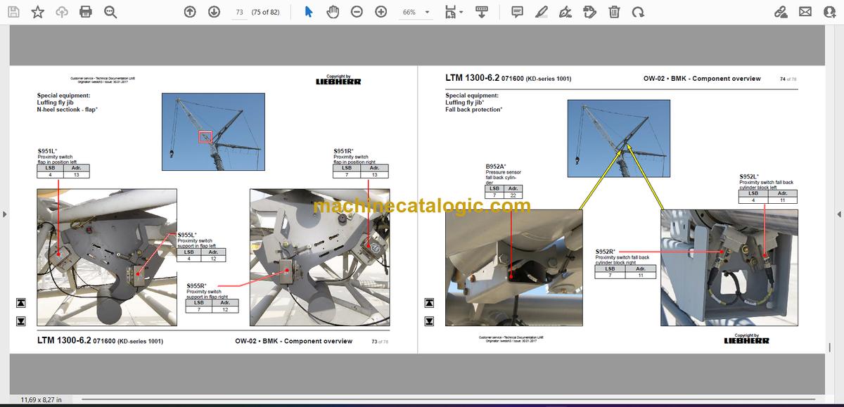
N-heel sectionk – flap*………………………………………………………….73
Fall back protection*……………………………………………………………74
N-head section*………………………………………………………………….75
►►Index:………………………………………………………………………… 76


