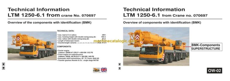
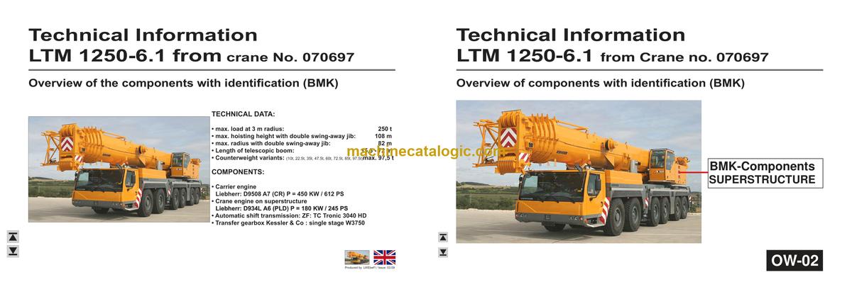
The Liebherr LTM 1250-6.1 Mobile Crane is a high-end all-terrain crane that earns or burns money every hour it’s on site. When something electrical or hydraulic acts up, the first person reaching for the BMK component identification is usually your workshop tech or field service guy trying to match a fault or wiring tag to a real part on the machine. The Technical Information & BMK Components Manual for Liebherr LTM 1250-6.1 Mobile Crane provides component identification diagrams, reference designators, and visual outlines used by technicians cross-referencing wiring or hydraulic schematics to physical parts on the crane. If your goal is fast pinpointing of components so you can plan parts, labor, and downtime, this is the type of document you want.
What this manual helps you do
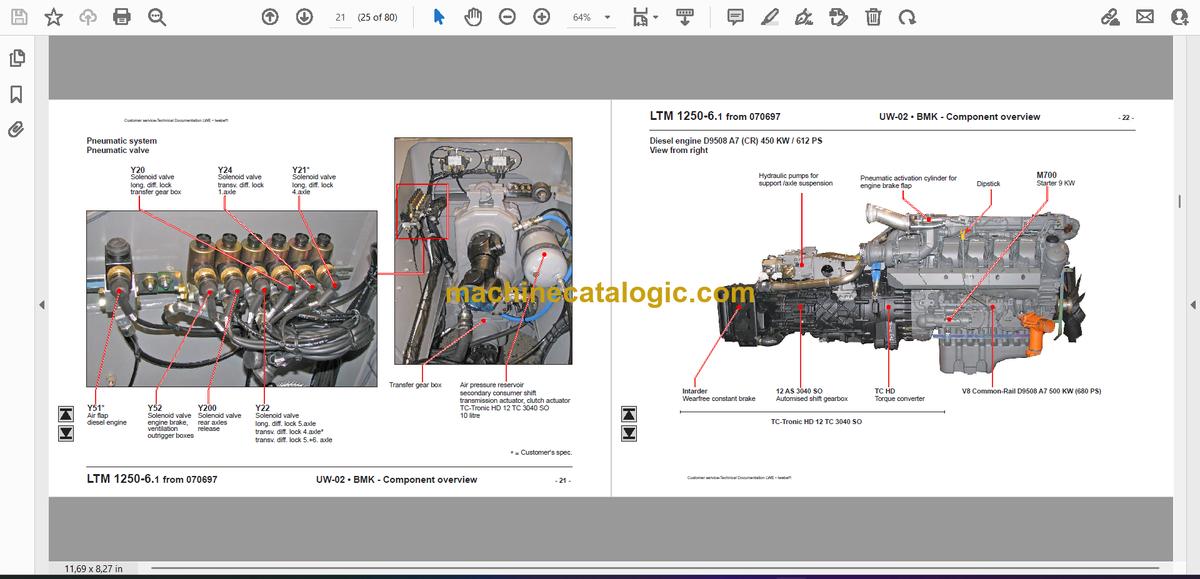
- Identify where specific electrical, hydraulic, or mechanical components sit on the carrier and superstructure using clear outline views.
- Locate components on the crane using their Liebherr reference designators (like K, V, E, X numbers) from wiring or hydraulic diagrams.
- Trace a fault code or schematic symbol to the exact physical component so you can decide whether to repair, swap, or order.
- Cross-reference component IDs with other Liebherr documentation (wiring diagrams, service data, parts lists) your shop already uses.
- Pinpoint major assemblies during technician training so new staff learn the machine layout without wasting time on guesswork.
Who this is for
This is aimed at workshop technicians, field service techs, electrical diagnostic engineers, fleet mechanics, and training instructors. If you need step‑by‑step repair procedures, torque specs, or part numbers, you’re better off with a service manual and parts catalogue, not this BMK.
FAQ
Q: Is the PDF clear and searchable enough for daily workshop use?
A: These manuals are usually provided as clear, zoomable PDFs where component diagrams and labels are readable on a laptop or tablet.
Q: Does it cover both carrier and superstructure for SN 070981?
A: Yes, this BMK product typically combines carrier and superstructure component identification for that serial number reference.
Q: Does it work together with other Liebherr manuals we already have?
A: Yes, it’s meant to be used alongside wiring diagrams, hydraulic schematics, service manuals, and parts catalogues by matching the same reference designators.
Bottom line: If you mainly need to find and name components fast on an LTM 1250-6.1 (SN 070981) to support diagnostics and planning, this is the right manual; if you want repair steps or part numbers, it’s not.
📘 Show Index
Table of Contents:
Carrier — Table of Contents
- Fahrzeug
- Ansicht von vorne, Beleuchtung und Spiegel
- Ansicht von hinten, Beleuchtung
- Seitenansicht rechts
- Seitenansicht links
- Fahrerhaus
- Innenbeleuchtung, Türkontaktschalter
- Heizung, Scheibenwischer
- Bedienelemente
- Lüfter, Wärmetauscher
- Batterien, Sicherungen
- Mittelkonsole- Sicherungen
- Mittelkonsole- Relais
- Mittelkonsole- E / A-Module
- Mittelkonsole- Steuergeräte, Bestückungsmodul
- Mittelkonsole- Heizflanschrelais
- Mittelkonsole- Diagnosestecker
- Druckluftanlage
- Druckgeber
- Lufttrockner, Kompressor
- Druckluftvorratsbehälter
- Pneumatikventile
- Dieselmotor D9508 A7 (CR) 450 KW / 612 PS
- Ansicht von rechts
- Ansicht von links
- Übersicht V-Raum
- Motorsteuergerät LH ECU UP/CR und Diagnosestecker
- Kraftstoff-Service-Center
- Kraftstoff-Pumpen mit Zumeßeinheit
- Raildruckgeber 1 und 2
- Ladelufttemperatur- und Ladeluftdruckgeber
- Kühlmitteltemperatur-Geber
- Injektoren und Zylinder-/ Bankzuordnung
- Übersicht Schwungradseite
- Drehzahlgeber
- Wassergekühlte externe Abgas-Rückführung
- Abgasturbolader mit Wastegate
- Übersicht Lüfterseite, Heizflansche
- Ölmodul mit Öldruckgeber
- Luftfilterunterdruck
- Kraftstoffvorwärmung und Tankgeber
- Autom. Schaltgetriebe TC-Tronic HD 12 TC 3040 SO
- Übersicht der Komponenten
- Übersicht Elektrik
- Drehmomentwandler
- Getriebe-/ Kupplungssteller
- Intarder
- Hydraulikpumpen
- Lenkkreis I und II, Achsfederung/Abstützung, Notlenkung
- Antriebsstrang
- Gelenkwelleneinbau
- Verteilergetriebe Kessler 1-stufig W3750
- Querdiff.- Sperren Achse 1 und 4
- Querdiff.- Sperren Achse 5 und 6
- Zuschaltung Antrieb Achse 4 und 5
- Wirbelstrombremse Telma Focal 2200 L 24V*
- Lenkung
- Lenkgetriebe, Mangelüberwachung
- Lenkunterstützung
- Hinterachslenkung Freischaltung Achse 3
- Hinterachsverriegelung, Hinterachslenkung
- Abstützung
- Abstützventile – Links,
Druckstufen
- Abstützventile – Rechts
- Drehdurchführung, Neigungsaufnehmer
- Stützkraftanzeige
- Öl Freigabe
- Achsfederung
- Niveaugeber
- Achsausgleich, Achsfederung
- Rückmeldung Achsausgleich
- Achsblockierventile Links
- Achsblockierventile Rechts
- Achse 3 und 4 anheben / ablassen
- Öl Freigabe
- Sonderausstattung
- Klimaanlage
- Zusatzheizung
- Fremdeinspeisung
- Fremdeinspeisung 24 V
- Index
Superstructure — Table of Contents
- Krankabine
- Steuerstand
- LICCON-Monitor, Pedale
- Meisterschalter 1 (Rechts)
- Meisterschalter 2 (Links)
- Bedienelemente Dachkonsole
- Kabineninstallation
- Radio, Scheibenwischer
- Diagnosestecker
- Heizung
- Zusatzheizung*
- Klimaanlage*
- Kranelektrik
- Batteriekasten
- Zentralschmierung
- Beleuchtung Drehbühne
- Vorbereitung EN 13000
- Schaltschrank
- Relais
- Sicherungen, Schlüsselschalter
- Sicherungen Notbetrieb ohne LICCON
- Relais, Stecker, Diodenplatine
- Eingangsplatinen, E/A-Modul 6
- Zentraleinheiten, Einbauteile
- Steckerblech
- Datenlogger, Spannungswandler
- Antriebsaggregat
- Dieselmotor D934 A6
- Einbauansicht
- Steckpumpen
- Kraftstoff-Wassersensor, -Temperatursensor
- Ladelufttemperatur und -druck
- Drehzahl- und Öldruckgeber
- Lüfterseite
- Kühlmittelniveau und -temperatur
- Motorsteuergerät, Diagnosestecker
- Kühler-Lüfterantrieb, Luftfilterunterdruck
- Luftklappe in Ansaugluft (Option)
- Druckluftanlage
- Kompressor, Lufttrockner
- Motorbremse
- Podest Kabine
- Kranhydraulik
- Übersicht Hydraulikpumpen
- Pumpe 1-3
- Pumpe 4-7
- Kühler, Temperaturschalter, Temperatursensor
- Nebenverbraucher
- Drehbühnenarretierung
- Kabine kippen
- Klappspitze Ansteuerung
- Drehwerk
- Ansteuerung, Inkrementalgeber
- Hubwerk
- Hubwerk 1 – Ansteuerung
- Hubwerk 1 – Winde
- Hubwerk 2* mit Verstellflasche – Ansteuerung
- Hubwerk 2* mit Verstellflasche – Links
- Hubwerk 2* mit Verstellflasche – Rechts
- Montagewinde – Ansteuerung
- Montagewinde – Winde
- Wippwerk
- Versorgung Wippen und Teleskopieren
- Steuerblock Wippen und Teleskopieren
- Druckgeber, Senkbremse
- Ansteuerung Senkbremse
- Ballastierung
- Druckversorgung
- Ansteuerung
- Teleskopausleger
- Ausschubmechanik „ Telematik“
- Televerbolzung
- Zangenverbolzung
- Notbetrieb ohne LICCON
- Elektrik
- Winkel- und Längengeber, Kabeltrommel
- Auslegerkopf
- Scheinwerfer Anlenkstück
- Zusatzausrüstung
- Wippbare Gitterspitze – Rollenkopf, Winkelgeber
- Wippbare Gitterspitze – Nadel / Positionsmeldung
- Wippbare Gitterspitze – Positionsmeldung „unten“
- Wippbare Gitterspitze – Anlenkstück
- Wippbare Gitterspitze – Rückfallzylinder
- Wippbare Gitterspitze – Zugmesslasche
- Index
- Crane cab
- Control stand
- LICCON-monitor, pedals
- Joystick 1 (right)
- Joystick 2 (left)
- Control elements roof panel
- Cab installation
- Radio, screen wiper
- Diagnosis plug
- Heating
- Additional heating*
- Air condition*
- Crane electric
- Battery box
- Central greasing
- Lighting slewing platform
- Preparation EN 13000
- Switch cabinet
- Relays
- Fuses, key switch
- Fuses emergency operation without LICCON
- Relays, plugs, diode board
- Input board, I/O-module 6
- Central unit, components
- Plug plate
- Data logger, voltage converter
- Drive assembly
- Diesel engine D934 A6
- Installation view
- Plug-in pumps
- Fuel-water sensor, temperature sensor
- Charge air temperature and pressure
- Engine speed and oil pressure sensor
- Ventilator side
- Cooling agent level and temperature
- Engine control unit, diagnosis plug
- Cooler ventilator drive, air filter vacuum
- Air flap in air suction (option)
- Pneumatic system
- Compressor, air dryer
- Engine brake
- Pedestal cab
- Crane hydraulic
- Overview hydraulic pumps
- Pumps 1-3
- Pumps 4-7
- Cooler, temperature switch, temperature sensor
- Aux. consumers
- Locking slewing platform
- Cab tilting
- Swing away jib activation
- Slewing gear
- Activation, incremental sensor
- Hoist gear
- Hoist gear 1 – activation
- Hoist gear 1 – winch
- Hoist gear 2* with luffing block – activation
- Hoist gear 2* with luffing block – left
- Hoist gear 2* with luffing block – right
- Assembly winch – activation
- Assembly winch – winch
- Luffing gear
- Supply luffing and telescoping
- Control block luffing and telescoping
- Pressure sensor, lowering brake
- Activation lowering brake
- Ballasting
- Pressure supply
- Activation
- Telescoipic boom
- Extension mechanism „ Telematik“
- Tele pinning
- Gripper pinning
- Emergency operation without LICCON
- Electric
- Angle- and length sensor, cabel drum
- Boom head
- Flood light heel section
- Additional equiipment
- Luffing lattice jib – sheave head, angle sensor
- Luffing lattice jib – needle / position indication
- Luffing lattice jib – position indication „down“
- Luffing lattice jib – heel section indication
- Luffing lattice jib – fall back cylinder
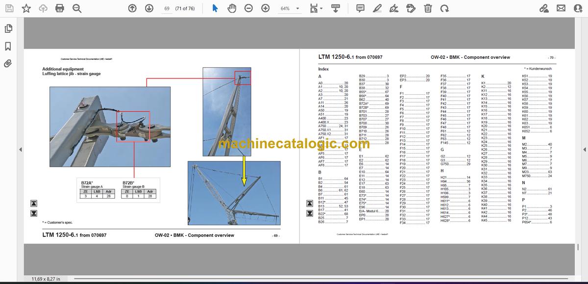
- Luffing lattice jib – strain gauge
- Index
- Cabina grù
- Comandi
- LICCON-Monitor, Pedali
- Manipolatore 1 (destro)
- Manipolatore 2 (sinistro)
- Elementi di comando Pannello superiore
- Installazioni cabina
- Radio, Tergicristalli
- Prese diagnosi
- Riscaldamento
- Riscaldamento addizionale*
- Climatizzatore*
- Impianto elettrico
- Vano batterie
- Ingrassaggio cenrtalizzato
- Illuminazione torretta
- Normativa EN 13000
- Armadio elettrico
- Relais
- Fusibili e interruttori a chiavetta
- Fusibili e manovre emergenza senza LICCON
- Relais, spine , scheda diodi
- Schede ingressi Modulo E/A 6
- Calcolatori centrali e componentistica
- Pannello prese
- Datenlogger, Trasformatore
- Gruppo trasmissione
- Motore diesel D934 A6
- Vista particolari
- Pompe singole
- Sensori temperatura carburante, refrigerante
- Sensori pressione e temperatura aria
- Sensori di giri e pressione olio motore
- Lato ventola
- Sensori livello e temperatura refrigerante
- Scheda gestione motore, Prese diagnosi
- Radiatore, trazione ventola e depressore aria
- Valvola a farfalla sulla aspirazione (A richiesta)
- Impianto aria
- Compressore, essicatore
- Freno motore
- Pedana cabina
- Impianto idraulico
- Veduta pompe idrauliche
- Pompe 1-3
- Pompe 4-7
- Radiatore,termostato e sensore temperatura
- Servizzi ausiliari
- Spinatura ralla
- Movimenti cabina
- Comandi falcone ripiegabile
- Rotazione
- Comandi e sensori incrementali
- Argano
- Argano 1 – Comando
- Argano 1 – Argano
- Argano 2* – Comando
- Argano 2* con gruppo puleggie – sinistro
- Argano 2* con gruppo puleggie – Destro
- Argano di montaggio – Comando
- Argano di montaggio – Argano
- Brandeggio braccio
- Alimentazione brandeggio e sfilo braccio
- Blocco comandi brandeggio e sfilo braccio
- Sensore di pressionevalvola discesa braccio
- Comando valvola discesa braccio
- Zavorramento
- Pressione alimentazione
- Comando
- Braccio telescopico
- Gruppo movimento braccio
- „ Telematik“ Spinatura elementi braccio
- Spinatura pinza
- Emergenza senza LICCON
- Elektrik
- Sensori di lunghezza e d‘angolo, avvolgicavo
- Testa braccio
- Fari da lavoro braccio base
- Allestimenti speciali
- Falcone a volata variabile – Testa carrucole, Sensore d‘angolo
- Falcone a volata variabile – Rilevamento posizione / punta
- Falcone a volata variabile – Rilevamento posizione (sotto)
- Falcone a volata variabile – Piede del falcone
- Falcone a volata variabile – Cilindro antiribaltamento
- Falcone a volata variabile – Cella di carico
- Indice
- Cabina de la grúa
- Puesto de mando
- Monitor LICCON, pedales
- Joystick 1 (lado derecho)
- Joystick 2 (lado izquierdo)
- Elementos de manejo, consola de techo
- Instalaciones en la cabina
- Radio, lavaparabrisas
- Conector de diagnóstico
- Calefacción
- Calefacción adicional*
- Sistema de aire acondicionado*
- Sistema eléctrico de la grúa
- Caja de la batería
- Sistema delubricación central
- Iluminaciónde la superestructura
- Preparación EN 13000
- Armario de distribución
- Relés
- Fusibles, interruptores de llave
- Fusibles, modo de emergencia sin LICCON
- Relés, conectores, placa de diodos
- Placas de entrada, módulo 6 E/S
- Unidades centrales, componentes
- Chapa de conectores
- Registrador de datos,transformador de tensión
- Grupo de accionamiento
- Motor diesel D934 A6
- Vista de montaje
- Bombas de inyección
- Sensor de agua-combustible, sensor de temperatura del combustible
- Temperatura y presión del aire de admisión
- Sensores de nº de revoluciones y de presión de aceite
- Lado del ventilador
- Nivel y temperatura del agente refrigerante
- Unidad de control del motor, conector de diagnóstico
- Accionamiento del ventilador de la unidad de refrigeración, presión negativa del filtro de aire.
- Estrangulador de aire en aire de aspiración (opcional)
- Sistema neumático
- Compresor, secador de aire
- Freno motor
- Plataforma de la cabina
- Sistema hidráulico de la grúa
- Bombas hidráulicas – Vista general
- Bombas 1 – 3
- Bombas 4 – 7
- Unidad de refrigeración, interruptor de temperatura, sensor de temperatura
- Consumidor secundario
- Enclavamiento de la superestructura
- Inclinar cabina
- Activación plumín rebatible
- Reductor de giro
- Activación, sensor incremental
- Mecanismo de elevación 1- Activación
- Mecanismo de elevación 1- Cabrestante
- Mecanismo de elevación 2* con bloque de polea – Activación
- Mecanismo de elevación 2* con bloque de polea – Lado izquierdo
- Mecanismo de elevación 2* con bloque de polea – Lado derecho
- Cabrestante de montaje – Activación
- Cabrestante de montaje – Cabrestante
- Mecanismo de elevación
- Alimentación subir/bajar pluma y telescopaje
- Bloque de control Elevar pluma y telescopar
- Sensor de presión,freno de descenso
- Pilotaje válvula de reducción
- Sistema de contrapesos
- Suministro de presión
- Activación
- Pluma telescópica
- Sistema mecánico de despliegue “Telemática”
- Embulonamiento del telescopio
- Embulonamiento pinzas
- Modo de emergencia sin LICCON
- Sistema eléctrico
- Sensor de ángulos y longitud, bobina de cable
- Cabeza de la pluma
- Faro tramo articulado
- Equipamiento adicional
- Plumín abatible hidraúlico – Cabeza de rodillos, sensor de ángulos
- Plumín abatible hidraúlico- Aguja / Indicación de la posición
- Plumín abatible hidraúlico – Indicación de posición “abajo”
- Plumín abatible hidraúlico – Tramo articulado
- Plumín abatible hidraúlico– Cilindro de retroceso
- Plumín abatible – Medidor de la tracción
- Índice
Liebherr Crane


