Format: PDF (Printable Document)
File Language: English
File Pages: 143
File Size: 11.23 MB (Speed Download Link)
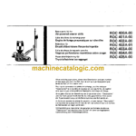
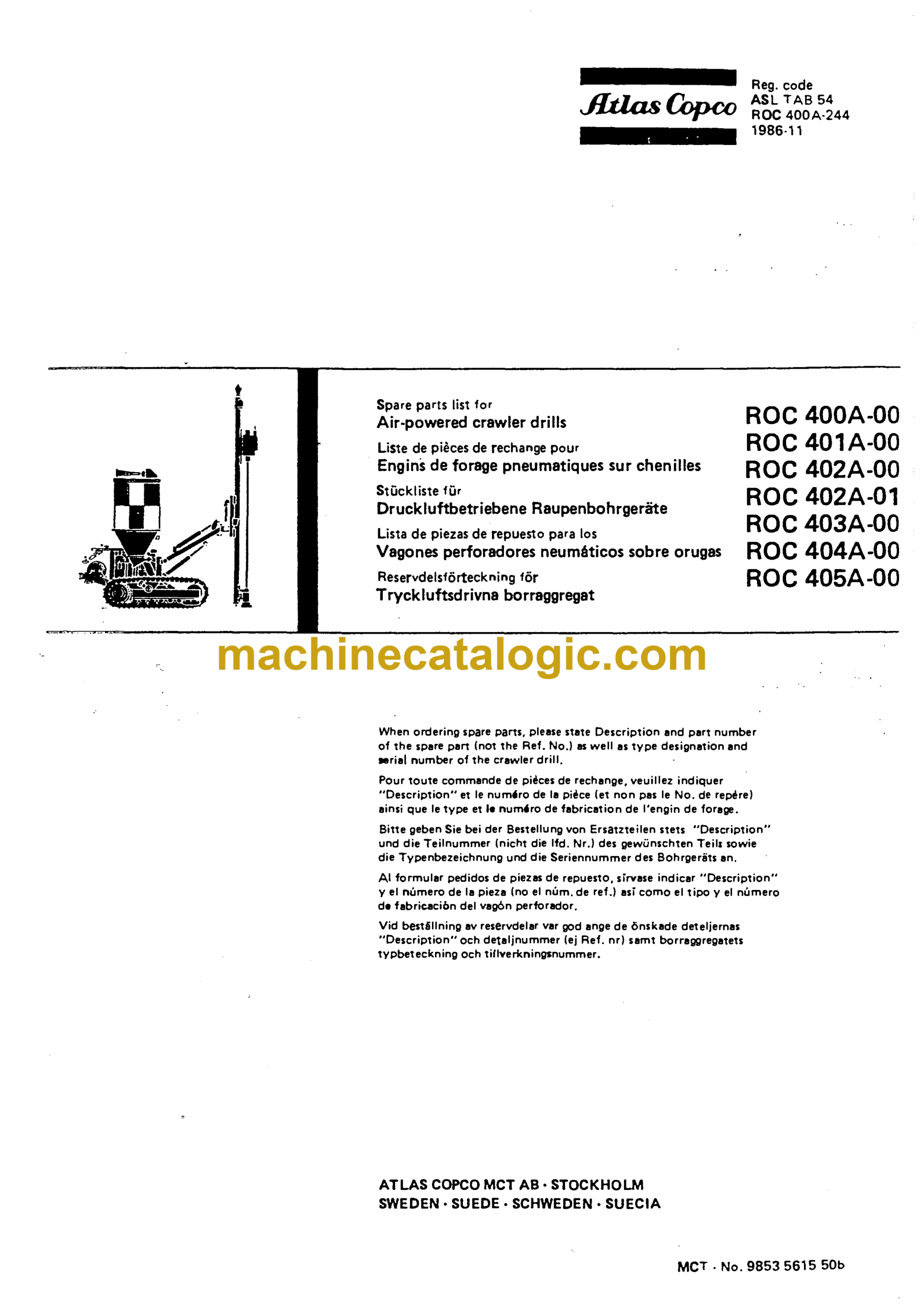
Brand: Atlas Copco
Model: 400A ROC
PM No: 9853 5615 50b
Type of Document: Parts Manual
ROC 400A-00
ROC 401 A-00
ROC 402A-00
ROC 402A-01
ROC 403A-00
ROC 404A-00
ROC 405A-00
$ 59
Feed CFA 701 36
Feed CFA 702 37
Feed CFA 1.02 39
Feed CFA 70* *1
Feed gear with motor 3216 291(6 83 *3
Feed gear with motor 3162 1530 67 *5
Cradle 3216 3766 80 (BBE 57-01) *6
Cradle 3216 3366 60 (COP 131EB) *7
Cradle 3216 WO 80 (COP 900) *8
Cradle 321* 2666 60 (COP 900) *9
Cradle 3216 3366 60 (BBR) 50
Drill steel support holder 3216 2165 61 51
Drill steel support for BBE 57-01 (138/7*5) 52
Drill steel support for COP 131EB (T36) 53
Drill steel support for COP 900 (H25/R26/R32/T38) 5*
Drill steel support for COP 900 (H25/R26/R32/T36) 55
Drill steel support for COP 32, <(2, 52 56
Swing arm 57
Front control panel 56
Front control panel 56
Front control panel 59
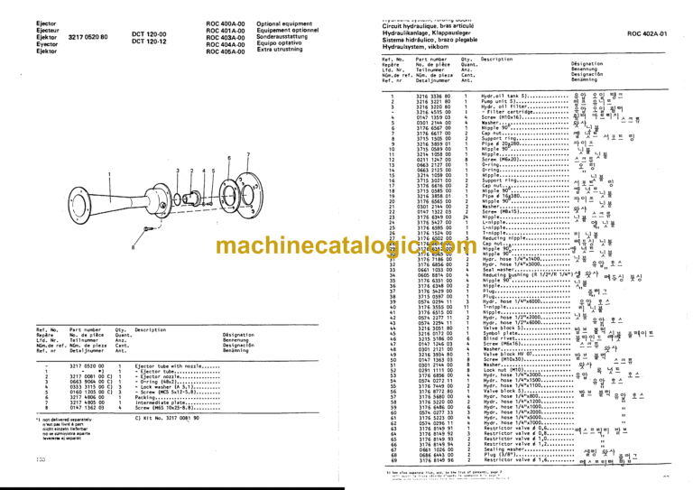
Hydraulic system, single boom version 61
Hydraulic system, folding boom 63
Valve block 3176 6772 60 65
Hydraulic oil tank 3216 3336 80 67
Pump unit 3216 3221 80 68
Air motor 8*11 1005 25 69
Double check valve 3176 5930 81 70
Valve block, track oscillation 3216 3051 80 71
Air system 6 bar 73
Air system f, bar 77
Air system 6 bar 63
Lubricating oil tank 3216 *757 60 88
Oil-fog lubricator 3216 *676 60 89
Air system 20 bar 91
Lubricating oil tank 3216 *757 80 86
Air valve 3163 0610 80 96
Condensed water valve 1612 06S5 80 97
Lubricating valve 9090 0159 80 98
Lubricating valve 3050 0051 60 96
Traction control **50 02*6 85 99
Rock drill control 8092 0109 10 101
Rock drill control 8092 0102 17 102
Control 3176 8162 80 103
Control panel 3176 6170 80 10*
Feed control 3176 7209 80 105
Rotation control 3176 7210 60 106
Impact control 3176 7211 60 107
Flushing control 3176 7212 60 108
Air system, drill steel retainer (COP 900) 109
Optional equipment ¥iDEt!_^it_8092_ 0101.3.*
Winch equipment 110
Winch equipment Ill
Air system, winch , 112
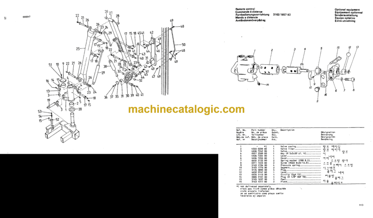
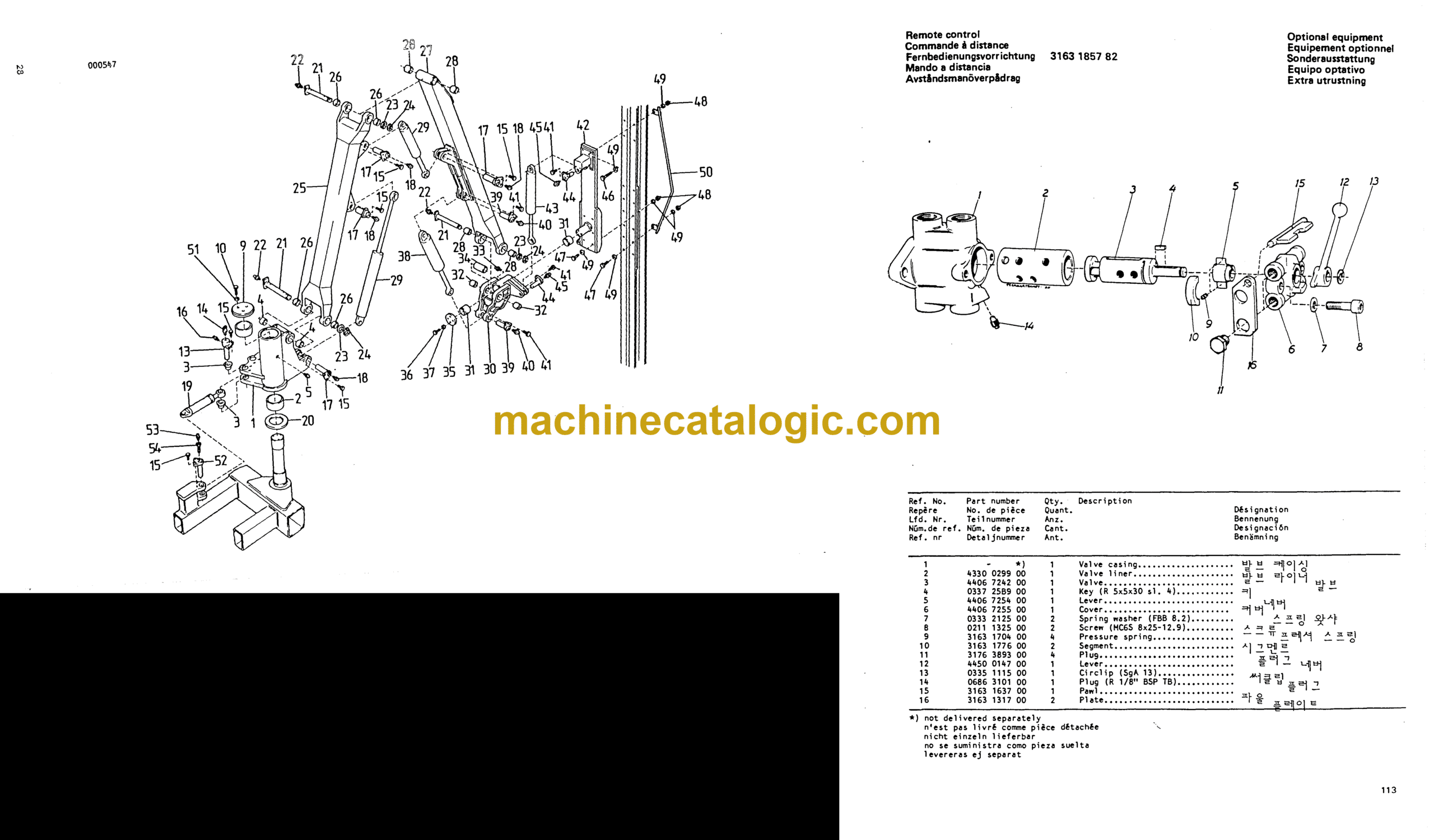
Remote control 3163 1857 82 113
E9uigr«nJ_set.wi th.cr{jle.for.BB|,5^ 11*
H. .Ci-ii£…BB.r._l_S.3J1_.*§_…0
Hydraulic support leg 115
Hydraulic system, support leg 116
Double check valve 3176 5930 61 70
PriIl_5jSSl.star>d_§CS2_9gg5.72 117
nrili_s.t.e.l._t..d__._2__170_._ 118
I. S5.r….§OS2.Qig…i
Tube rack 119
Hydraulic system, tube rack 120
Hydraulic cylinder 3176 3226 61 121
Oust collector OCT 50-07, 50-08, 120-00, 120-12, 220-09
.Wi.8_l..ll»_S.l…Za.Q.l..Z.».Q-lS.51a.8Sli-Z7 12J
Filter unit 3217 *826 80 OCT 50-07, 50-08 125
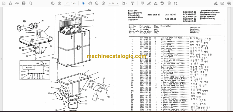
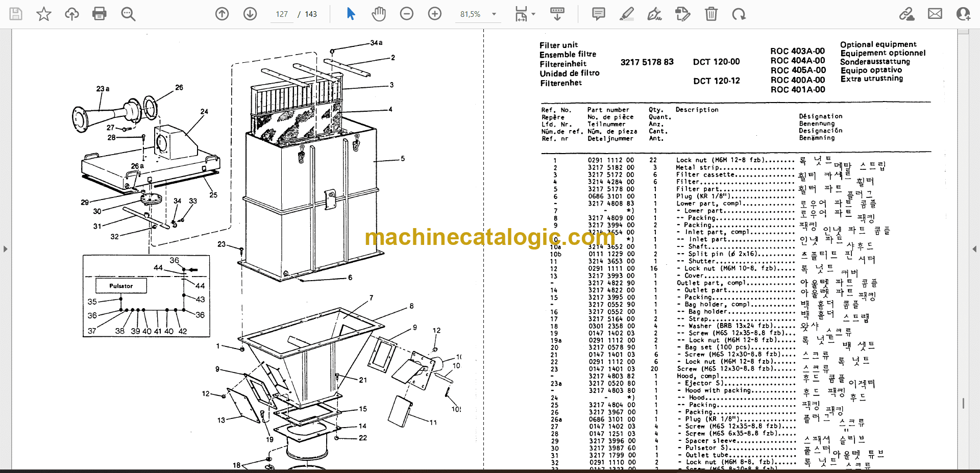
Filter unit 3217 5176 63 OCT 120-00, 120-12 127
Filter unit 3217 5167 80 OCT 220-09 129
Ejector 3217 0520 B0 OCT 120-00, 120-12 130
Ejector 3217 3966 80 OCT 220-09 131
Ejector 3217 2959 60 OCT 50-07, 50-08 132
Pulsator 3217 3987 80 133
Pulsetor 3217 5307 90 13*
Pulsator 3217 3987 81 135
Suspension kit for OCT 50-07, 120-00, 120-12, 220-09 135
Suspension kit for OCT 50-08 136
Skirt 3217 5325 B0 137
Assembly kit for DCT 50 321* 3*50 80 138
Assembly kit for DCT 120-00, 120-12, 220-09 3216 *033 80 139
Air system OCT 50-07, 50-08 1*0
Air system DCT 120-00, 120-12 1*1
Air system OCT 220-09
CHssière CFA 700 35
Clissière CFA 701 36
Clissière CFA 702 37
Cliisière CFA »02 39
Clissière CFA 70* »1
Réducteur de glissière et moteur 3216 29*6 83 »3
Réducteur de glissière et moteur 3162 1530 67 »,
Berceau 3216 3766 80 (BBE 57-01) »6
Berceau 3216 3368 80 (COP 131EB) »7
Berceau 3216 »»»0 80 (COP 900) »8
Berceau 321» 2868 80 (COP 900) »9
Berceau 3216 3366 80 (BBR) 50
Support d’éteu-guide 3216 2185 81 51
Etau-guide pour BBE 57-01 (T38/T»5) 52
Etau-guide pour COP 131EB (T38) 53
Etau-guide pour COP 900 (H2S/R28/R32/T38) 5»
Etau-guide pour COP 900 (H25/R28/R32/T38 ) 55
Etau-guide pour COP 32, »2. 52 56
Bras pivotent 57
Tableau avant de commande 58
Tableau avant de commande 58
Tableau avant de commande 59
Circuit hydraulique, modèle i bras fixe 61
Circuit hydraulique, bras articulé 63
Bloc de distributeurs 3176 8772 80 65
Réservoir d’huile hydraulique 3216 3336 80 67
Centrale hydraulique 3216 3221 80 68
Moteur 1 air comprimé 8*11 1005 25 69
Double clapet anti-retour piloté 3176 5930 81 70
Bloc de distributeurs, oscillation des chenilles 3216 3051 80 71
Circuit pneumatique, 6 bars 73
Circuit pneumatique, 6 bars 77
Circuit pneumatique, 6 bars 83
Réservoir d’huile de graissage 3216 »757 80 86
Graisseur par pulvérisation d’huile 3216 »676 60 89
Circuit pneumatique, 20 bars 91
Réservoir d’huile de graissage 3216 »757 80 88
Valve pneumatique 3163 0610 80 96
Purgeur d’eau de condensation 1612 0685 80 97
Valve de graissage 9090 0159 80 98
Valve de graissage 3050 0051 80 98
Commande de traction »»50 02»6 85 99
Commande du marteau-perforateur 8092 0109 10 101
Commande du marteau-perforateur 8092 0102 17 102
Commande 3176 8182 80 103
Tableau de commande 3176 8170 80 10»
Commande de la glissière 3176 7209 80 105
Commande de rotation 3176 7210 80 106
Commande du mécanisme de percussion 3176 7211 60 107
Commande de soufflage 3176 7212 80 106
Circuit pneumatique, décaleur (COP 900) 109
Equipement optionnel Ireuil.8092.01p1J»…
Equipement de treuil 110
Equipement de treuil 111
Circuit pneumatique, treuil 112
Commande i distance 3163 1857 62 113
-î..-1.9yie…Dî.e..berces…o.r.Bfi^ 11»
.vee.rt_hv.reyliguj.321§.».?6.80
Jambe support hydraulique 115
Circuit hydraulique, jambe support 116
Double clapet anti-retour piloté 3176 5930 81 70
5î.ïii.:.ê-SileDS.i..Q??.Q.0..72 117
.iî.li.r.i.ill9Dgï..SO§2.oijo.jg us
.i..li.r.i..”Bi..§Q22.Q!°2.»1
Rîtelier 1 tubes 119
Circuit hydraulique rîtelier 1 tubes 120
Vérin hydraulique 3176 3226 81 121
Dépoussiéreur DCT 50-07, 50-08, 120-00, 120-12, 220-09
.Q?2.0*13.111.0»1J.}7J.0.13.Z§..0»1».51 ..0»1».77 123
Ensemble filtre 3217 »826 80 DCT 50-07, 50-08 125
Ensemble filtre 3217 5176 83 DCT 120-00, 120-12 127
Ensemble filtre 3217 5167 60 DCT 220-09 129
Ejecteur 3217 0520 80 DCT 120-00, 120-12 130
Ejecteur 3217 3966 80 DCT 220-09 131
Ejecteur 3217 2959 80 DCT 50-07, 50-08 132
Pulsateur 3217 3987 80 , 133
Pulseteur 3217 5307 90 13»
Pulsateur 3217 3987 81 135
Dispositif i suspension pour DC1 50-07, 120-00, 120-12, 220-09 135
Dispositif i suspension pour DCT 50-08 136
Jupe 3217 5325 80 137
Jeu de montage pour DCT 50 321» 3»50 80 138
Jeu de montage pour DCT 120-00, 120-12, 220-09 3216 »033 80 139
Circuit pneumatique DCT 50-07, 50-08 1*0
Circuit pneumatique DCT 120-00, 120-12 1»!
Circuit pneumatique DCT 220-09 1<|2
Distributeur 321* »»50 80 1*3
Vorschubeinrichtung CFA 701 36
Vorschubeinrichtung CFA 702 37
Vorschubeinrichtung CFA »02 39
Vorschubeinrichtung CFA 70» * »1
Vorschubgetriebe mit Motor 321 6 29»6 83 »3
Vorschubgetriebe mit Motor 3162 1530 87 »5
Schlitten 3216 3768 80 (BBE 57-01) »6
Schlitten 3216 3368 80 (COP 131F.6) »7
Schlitten 3216 »»»0 80 (COP 900) »8
Schlitten 321» 2868 80 (COP 900) »9
Schlitten 3216 3366 80 (BBR) 50
Hilter 3216 2185 81 51
Bohrstütze für BBC 57-01 (T38/H5) 52
Bohrstütze für COP 131EB (T38) ; 53
Bohrstüt2e für COP 900 (H25/R28/R32/T38) 5»
Bohrstütze für COP 900 (H25/R28/R32/T38) 55
Bohrstütze für COP 32, »2, 52 56
Schwenkarm , 57
Bedienungstafel vorn 58
Bedienungstafel vorn 56
Bedienungstafel vorn 59
Hydraulikanlage, Ausführung mit einfachem Ausleger 61
Hydraulikanlage, Ausführung mit Klappausleger 63
Ventilblock 3176 8772 80 65
Hydraul ikölbeh’alter 3216 3336 80 67
Pumpeneinheit 3216 3221 80 68
Druckluftmotor 8»11 1005 25 69
Hydroschloss 3176 S930 81 70
Ventilblock, Reupenpendeln 3216 3051 80 ; 71
Druckluftanlage, 6 bar 73
Druckluftanlage, 6 bar 77
Druckluftanlage, 6 bar 63
Schmier Ölbehälter 3216 »757 80 88
01 nebelschmierapparat 3216 »676 60 89
Druckluftanlage, 20 bar 91
Schmierölbehälter 3216 »757 80 86
Druckluftventil 3163 0610 80 96
Kondensatventil 1612 0685 80 97
Schmierventil 9090 0159 80 98
Schmierventil 30S0 0051 80 98
Fahranlasser »»50 02*8 85 99
Bohrhammeranlasser 8092 0109 10 101
Bohrhammeranlesser 6092 0102 17 102
Anlasser 3176 8182 80 1°3
Bedienungstefel 3176 8170 80 104
Vorschubventil 3176 7209 60 105
Rotetionsventil 3176 7210 80 106
Schlegwerkventil 3176 7211 80 1°7
Spülventil 3176 7212 80 106
Druckluftanlage, Bohrerhalter (COP 900) ,09
Sonderausstattunq SIDS?. §.52.0101.3»
Windenausrüstung 110
Windenausrüstung III
Druckluftanlage, Winden 112
Fernbedienungsvorrichtung 3163 1857 62 113
*¥.-…¥n8.-..l..İ-.ŞS-lİ_-.D.Î.C.-ŞL. 11*
…r«.
liÇheş.Şt5t|bj.n_3216.*696.8g
Hydreuliches Stützbein 115
Hydraulikanlage, Stützbein 116
Hydroschloss
317
6 5930 81 70
_..DK.9…sll….-.M.-.Z- m
5t50iSD.îi.îll.S52i.91Z5.35 118
Ç..rg..tîll.|.?2.eie2.»l
Rohrgestell 119
Hydraulikanlage, Rohrgestell 120
Hydrozylinder
317
6 3226 81 121
Staubabscheider DCT
50-07
, 50-08, 120-00, 120-12, 220-09
SOT2-e413-ll-.Wl2-32..K!5.Z§..«l*.51,-$i!l.-ZZ i»
Filtereinheit
321
7 *826 80 DCT 50-07, 50-08 125
Filtereinheit
321
7 5178 83 DCT 120-00, 120-12 127
Filtereinheit
321
7 5167 80 DCT 220-09 129
Ejektor
321
7 0520 80 DCT 120-00, 120-12 130
Ejektor
321
7 3966 80 DCT 220-09 131
Ejektor
321
7 2959 80 DCT 50-07, 50-08 132
Pulsator
321
7 3987 80 133
Pulsator
321
7 5307 90 13*
Pulsator
321
7 3987 81 135
Aufhängevorrichtung für DCT
50-07
, 120-00, 120-12, 220-09 135
Aufhängevorrichtung für DCT 50-08 136
Clocke
321
7 5325 80 137
Hontagesatz für DCT
5
0 321» 3*50 80 138
Montagesatz für DCT
120-00
, 120-12, 220-09 3216 »033 80 139
Druckluftanlage DCT 50-07, 50-08 1*0
Druckluftanlage DCT
120-00
, 120-12 1*1
Druckluftanlage DCT 220-09 1*2
Wegeventil
321
» »»50 80 1»
Des) izadera CFA 700 35
Deslizadera CFA 701 36
Desl izadera CFA 702 37
Deslizadera CFA »02 39
Deslizadera CFA 70» »1
Engranaje de la deslizadera con motor 3716 29»6 83 »3
Engranaje de la deslizadera con motor 3162 1530 67 »5
Soporte 3216 3768 60 (BBE 57-01) »6
Soporte 3216 3368 80 (C0P 131EB) »7
Soporte 3216 »»»0 60 (C0P 900) »8
Soporte 321» 2866 80 (COP 900) »9
Soporte 3216 3 366 80 (BBR) 50
Soporte de gula de barrenas 3216 2165 81 51
Guia de barrenas para BBE 57-01 (T38/T»5) 52
Cuta de barrenas para COP 131EB (T36) 53
Guia de barrenas par» COP 900 (H2S/R28/R32/T38) S»
Cule de barrenas per» COP 900 (H25/R28/R32/T3B) 55
Cui» de barrenas para COP 32, »2, 52 56
Brazo móvil …, 57
Panel delantero de control 56
Panel delantero de control 58
Panel delantero de control 59
Sistema hidráulico, modelo con brazo sencillo 61
Sistema hidriuüco, modelo con brezo plegable 63
Bloque de válvulas 65
Depósito del aceite hidráulico 3216 3336 80 67
Unidad de bombas 3216 3221 80 66
Motor de aire comprimido 8»11 1005 25 69
Cierre hidráulico 3176 5930 61 70
Bloque de válvulas, inclonaci6n de las orugas 3216 3051 60 71
Sistema neumático, 6 bares 73
Sistema neumático, 6 bares 77
Sistema neumático, 6 bares 83
Depósito de aceite lubricante 3216 »757 60 88
Engrasador de neblina de aceite 3216 »676 80 89
Sistema neumático, 20 bares 91
Depósito de aceite lubricante 3216 »757 80 88
Válvula neumática 3163 0610 80 96
Válvula de agua condensada 1612 0685 80 97
Válvula de engrase 9090 0159 80 98
Válvula de engrase 3050 0051 80 98
Mando de propulsión »»50 02»6 85 99
Mando de la perforadora 8092 0109 10 101
Mando de la perforadora 6092 0102 17 102
Control 3176 6182 80 103
Panel de control 3176 8170 80 10»
Control del avance 3176 7209 80 105
Control de rotación 3176 7210 80 106
Control del mecanismo de percusión 3176 7211 80 107
Control de berrido 3176 7212 80 108
Sistema neumático, retenedor de barrena (COP 900) 109
Equipo optativo
C4brest.nte.fg92.9191.3»
Equipo de cabrestante 110
Equipo de cabrestante 111
Sistema neumático, cabrestante 112
Mando a distancia
3163 1657 82 113
.u.S9–.-.–ÍE.–90.i..9…_B-C….–.Z:.^ • • • 11*
.69.5.-1.:.
ylíSS.321§.»696.8g
Pata de apoyo hidráulica 115
Sistema hidráulico, pata de apoyo 116
Cierre hidráulico 3176 5930 81 70
Alm.E.D……EC.2…80?..ggg5.Z2 117
AÍM..-……r..enas.8922.g!7g.3g US
l2.9r…9′..Y.:Íllíj..8g?2.gig2.»1
Soporte de varillaje 119
Sistema hidráulico, soporte de varillaje 120
Cilindro hidráulico
317
6 3226 81 121
Colector de polvo DCT
50-07
, 50-08, 120-00, 120-12, 220-09
.M__P*i__ii._Mi_._z.^ 123
Unidad de filtro
321
7 »826 80 DCT 50-07, 50-08 125
Unidad de filtro
321
7 5178 83 DCT 120-00, 120-12 127
Unidad de filtro
321
7 5167 80 DCT 220-09 129
Eyector
321
7 0520 80 DCT 120-00, 120-12 130
Eyector
321
7 3966 80 DCT 220-09 131
Eyector
321
7 2959 80 DCT 50-07, 50-08 132
Pulsador
321
7 3987 80 133
Pulsador
321
7 5307 90 13»
Pulsador
321
7 3987 81 135
Dispositivo de suspensión para DCT
50-07
, 120-00, 120-12, 220-09 135
Dispositivo de suspensión para DCT 50-08 136
Faldón
321
7 5325 80 137
Accessories de montaje para DCT 50 321» 3»50 80 138
Accessories de montaje para DCT 120-00, 120-12, 220-09 3216 »033 80 139
Sistema neumático DCT 50-07, 50-08 1»0
Sistema neumíticc DCT 120-00, 120-12 1»1
Sistema neumático DCT 220-09 1»2
Vílvula direccional 321» »»50 80 1»3
Katere CFA 700 35
Kater« CFA 701 3t
«atar*
CF
A 702 37
Katert CfA 1.02 39
Matare
Cf
A 70* »1
Hatarvenel metí motor 1216 29*6 63 »3
Meterva*el med motor 3162 1530 67 »5
Slade 3216 3766 60 (BBE 57-01) *6
Slade 3216 3368 80 (COP 131EB) *7
Slade 3216 *»*0 80 (COP 900) *8
Slade 321* 2860 80 (COP 900) *9
Släde 3216 3366 80 (BBR) 50
Borrttödshillare 3216 2185 81 51
Borrttöd fbr BBC 57-01 (T38/W5) 52
Borrstöd för COP 131EB (T38) 53
Bernte« för COP 900 (H25/R28/R32/T38) 5»
Borrstöd för COP 900 (H25/R28/R32/T38) 55
Borr.tod för COe 32, *2, 52 56
Svängarro 57
Främre manöverpanel •• 56
Främre manöverpanel 56
Prämre manöverpanel 59
KrdraulSystem, enkelbomsversion 61
l+vdreul System vikbom 63
“ventilblock 3176 8772 60 65
Hydreulcljetenk 3216 3336 80 67
Pumpenhet 3216 3221 80 68
Luftmotor 6*11 1005 25 69
Hydraullis 3176 5930 81 70
Ventilblock, bandpendling 3216 3051 80 71
Ufftsysten, 6 bar 73
Luftsystee, 6 bar 77
U.-ftsyitem, 6 bar 63
Smörjoljebehallare 3216 *757 80 86
Dimsmörjapparet 3216 *676 80 69
Luftsystee, 20 bar 91
Snörjoljebehellare 3216 *757 80 88
Luftventil 3163 0610 80 96
Kondensvettenventi 1 1612 0685 80 97
Smörjventll 9090 0159 80 98
Smbrjventil 3050 0051 80 98
Akpidre; 4*50 02*8 85 99
BorrmasMnspedreg 8092 0109 10 101
Sorrmaskinspidreg 6092 0102 17 102
Padre;
317
6 8182 80 103
Manöverpanel 3176 8170 80 10*
Matnincsventil 3176 7209 60 105
Rotationsventil 3176 7210 80 106
Slagverksventil 3176 7211 60 107
Spolnincsventil 3176 7212 80 108
Luftsystetr, borrhillare (COP 900) 109
Extra utrustnino .Í…–..–91.1…
Vi nehutrustMng 110
Vi nsehutrustning 111
Luftsystesr, vinch 112
Avstandssanöverpädrag 3163 1857 62 113
.i….-Í0S5..-S.TC…1.9’í-!.C–?É-5Z:91-TC-^^ 11*
.I.r.Wli..s-…-..D..216.*§%.60
Hydrauliskt stödben 115
hyereulsystem, stödben 116
Hydraullis 3176 5930 81 70
…. 8.-5 II.!???. 0005.72 117
5;..a..ill.?..i.ei7o.jQ 118
S. r.3.-!!.??..-919..*1
Rörställ 119
HyireulSystem, rörstil! 120
Hydraulcyltnder 3176 3226 81 121
Dawnevski!jare OCT 50-07, 50-08, 120-00, 120-12, 220-09
Se.L9.1..ii.i.PiiK.Z..9.!..78.-0*i*..i,.o* 123
Filterenhet 3217 *826 80 OCT 50-07, 50-08 125
FUterenhet 3217 5178 83 OCT 120-00, 120-12 127
Filterenhet 3217 5167 80 OCT 220-09 129
Ejektor 3217 0520 80 DCT 120-00, 120-12 130
Ejektor 3217 3966 80 DCT 220-09 131
Ejektor 3217 2959 80 DCT 50-07, 50-08 132
Pulsator 3217 3987 80 133
Pulsator 3217 5307 90 13*
Pulsetor 3217 3967 81 135
Upphängningsenordning för DCT 50-07, 120-00, 120-12, 220-09 135
Upphängningsanordning för DCT 50-06 136
(Cjol 3217 5325 80 137
Monteringssets för DCT 50 321* 3*50 80 138
Monteringssets för DCT 120-00, 120-12, 220-09 3216 *033 80 139
Luftsystem DCT 50-07, 50-08 1*0
Luftsystem DCT 120-00, 120-12 1*1
Luftsystem DCT 220-09 1*2
