The Bobcat 2100 is a small utility vehicle for jobsite hauling, grounds work, and farm chores, more like a Gator than a skid steer. The people who reach for this manual are the ones actually turning wrenches: shop mechanics, field techs, and owners who are tired of guessing. They want wiring colors, torque specs, and step-by-step teardown info so they can fix it once and move on to the next job.
What this manual helps you do
- Diagnose no-start, charging, and lighting problems by following wiring diagrams and test steps
- Trace and repair drive system issues like poor pulling power, odd noises, or no movement
- Check, adjust, and replace steering, suspension, and brake components after wear or damage
- Follow teardown and reassembly procedures on the engine, transaxle, and driveline parts
- Set and verify linkages, cables, and adjustments after parts replacement so it actually drives right
Who this is for
If you own or maintain a Bobcat 2100 in the serial range 522711001-522799999 and you plan to do real repair work, this is the right book. Small contractors, rental fleets, farm shops, and owner-operators who already know basic tools will get the value. If you only need how to drive it or basic daily checks, you want the operator's handbook instead.
FAQ
Q: Is this a searchable PDF, and can I read the wiring diagrams on a laptop or tablet?
A: Yes, this is a PDF service manual, and in my experience the wiring pages are drawn to be zoomed on-screen and printed if needed.
Q: How do I know it fits my exact 2100?
A: Check your machine serial number. If it falls between 522711001 and 522799999, this is the correct manual for your unit.
Q: Is this what I need for real repairs, not just maintenance schedules?
A: Yes, this is the workshop-level service manual, the one techs use for diagnostics, teardown, and reassembly.
Bottom line: If your Bobcat 2100's serial number is in that range and you're planning to actually repair it, this is the manual you want. If it's outside that range, skip this one.
📘 Show Index
Table of Contents:
- Section 1 – Safety
- General Warning
- Section 2 – Vehicle Specifications
- Section 3 – General Information
- General Information
- Serial Number Identification
- Storage
- Preparing the Vehicle for Extended Storage
- To Return Vehicle to Service
- Section 4 – Body and Trim
- Cleaning the Vehicle
- Front Body Repair
- Abrasions and Haze
- Light Scratches
- Large Scratches and Abrasions
- Front Body Components
- Dashboard Removal
- Dashboard Installation
- Front Body Removal
- Front Fender Removal
- Front Fender Installation
- Front Body Installation
- Seat
- Front Seat Support
- Front Seat Support Removal
- Front Seat Support Installation
- Rear Seat Support
- Rear Seat Support Removal
- Rear Seat Support Installation
- Cargo Bed
- Cargo Bed Removal
- Cargo Bed Installation
- Bed Stop Bumper Adjustment
- Rear Fender
- Rear Fender Removal
- Rear Fender Installation
- Tailskirt
- Tailskirt Removal
- Tailskirt Installation
- Receiver Hitch
- Receiver Hitch Removal
- Receiver Hitch Installation
- Floor Mat
- Floor Mat Removal
- Floor Mat Installation
- Section 5 – Accelerator and Brake Pedal Assemblies
- Brake Pedal
- Brake Pedal Removal
- Brake Pedal Installation
- Brake Pedal Adjustment
- Accelerator Pedal
- Accelerator Pedal Removal
- Accelerator Pedal Installation
- Accelerator Pedal Adjustment
- Section 6 – MC012C-AS00 Transaxle: Hydraulic and Park Brake Systems
- Brake System Inspection
- Brake System Troubleshooting
- Brake Drum Removal
- Front Wheel Brake Drum Removal
- Rear Wheel Brake Drum Removal
- Brake Shoe Removal
- Front Brake Shoe Removal
- Rear Brake Shoe Removal
- Brake Cluster Inspection and Cleaning
- Brake Shoe Installation
- Front Brake Shoe Installation
- Rear Brake Shoe Installation
- Brake Drum Installation
- Front Wheel Brake Drum Installation
- Rear Wheel Brake Drum Installation
- Brake Cluster Assembly Replacement
- Front Brake Cluster Assembly Removal
- Front Brake Cluster Assembly Installation
- Rear Brake Cluster Assembly Removal
- Rear Brake Cluster Assembly Installation
- Wheel Cylinder Replacement
- Front Wheel Cylinder Removal
- Front Wheel Cylinder Installation
- Rear Wheel Cylinder Removal
- Rear Wheel Cylinder Installation
- Brake Shoe Adjuster Replacement
- Front Brake Shoe Adjuster Removal
- Front Brake Shoe Adjuster Installation
- Rear Brake Shoe Adjuster Removal
- Rear Brake Shoe Adjuster Installation
- Hydraulic Line and Hose Replacement
- Front Brake Line Removal
- Front Brake Line Installation
- Front Brake Hose Assembly Removal
- Front Brake Hose Assembly Installation
- Rear Brake Line Removal
- Rear Brake Line Installation
- Rear Brake Hose Removal
- Rear Brake Hose Installation
- Master Cylinder And Bell Crank Replacement
- Bell Crank Removal
- Bell Crank Installation
- Master Cylinder Removal
- Master Cylinder Installation
- Bleeding the Hydraulic Brake System
- Purging the Hydraulic System
- Filling the Hydraulic System
- Park Brake System
- Park Brake Cable Removal
- Park Brake Cable Installation
- Park Brake Handle Removal
- Park Brake Handle Installation
- Park Brake Adjustment
- Section 7 – Steering and Front Suspension
- Steering Wheel
- Steering Wheel Removal
- Steering Wheel Installation
- Steering Column
- Steering Column Removal
- Steering Column Disassembly
- Steering Column Assembly
- Steering Column Installation
- Rack and Pinion
- Rack and Pinion Removal
- Rack and Pinion Disassembly
- Rack and Pinion Assembly
- Rack and Pinion Installation
- Front Suspension
- Lubrication
- Wheel Alignment
- Front Suspension Components
- Kingpin and Steering Spindle Removal
- Kingpin and Steering Spindle Installation
- A-Arm Removal
- A-Arm Installation
- Shock Absorber Removal
- Shock Absorber Installation
- Front Wheel Bearings and Hubs
- Front Wheel Free Play Inspection
- Front Wheel Bearings and Hub Removal
- Front Wheel Bearings and Hub Installation
- Section 8 – Wheels and Tires
- General Information
- Section 9 – Rear Suspension
- Shock Absorbers
- Shock Absorber Removal and Inspection
- Shock Absorber Installation
- Multi-Leaf Springs
- Multi-Leaf Spring Removal
- Multi-Leaf Spring Installation
- Snubber
- Snubber Removal
- Snubber Installation
- Section 10 – Periodic Maintenance
- Periodic Service Schedule
- Periodic Lubrication Schedule
- Master Cylinder
- Engine Oil
- Engine Oil Level Check
- Engine Oil and Filter Change
- Oil Viscosity
- Fueling Instructions
- Battery
- Section 11 – Troubleshooting and Electrical System: FE400 Engine
- Troubleshooting Guide
- Electrical System
- Wiring Diagram
- Electrical Circuits
- Starter Circuit
- Generator Circuit
- Engine Ignition Circuit
- Engine Kill Circuit
- Reverse Buzzer Circuit
- Low Oil Warning Circuit
- Lockout Cam Circuit
- Fuel Gauge and Sending Unit Circuit
- Hour Meter Circuit
- Lighting Circuit
- Circuit Testing
- Testing the Starter Circuit and Generator Circuit
- Testing the Engine Ignition Circuit
- Testing the Engine Kill Circuit
- Testing the Reverse Buzzer Circuit
- Testing the Low Oil Warning Circuit
- Testing the Lockout Cam Circuit
- Testing the Fuel Gauge and Sending Unit Circuit
- Testing the Lighting Circuit
- Test Procedures
- Section 12 – Electrical Components: FE400 Engine
- Starter/Generator
- Voltage Regulator
- Diode
- Key Switch
- Solenoid
- Fuse
- Lockout Cam Limit Switch
- Lockout Cam
- Reverse Warning Buzzer
- Reverse Buzzer Limit Switch
- Low Oil Warning Light
- Fuel Gauge/Hour Meter
- Fuel Level Sending Unit
- RPM Limiter
- Ignition Coil
- Oil Level Sensor
- Headlights
- Headlight Diode
- Light Switch
- Battery
- Ground Straps
- Section 13 – FE400 Engine
- General Information
- Before Servicing
- Lubrication System
- Spark Plug
- Cylinder
- Breather Valve (Reed Valve)
- Valve Clearance Check and Adjustment
- Crankcase
- Engine Removal
- Crankcase Cover Removal
- Oil Level Sensor
- Ignition Coil and Flywheel
- Crankcase Cover Installation
- Flywheel Installation
- Engine Installation
- Torque Specifications
- Adjustment and Settings
- Section 14 – Fuel System
- General Information
- Carburetor
- Main Jet Elevation/Size Chart
- Changing the Main Jet
- Engine Control Linkage
- General Information
- Accelerator Rod
- Governor Cable
- Accelerator Cable
- Closed Throttle or Idle Adjustment
- Engine RPM Adjustment
- Choke and Air Intake System
- Choke Cable Removal
- Choke Cable Installation
- Air Box Removal
- Air Box Installation
- Intake Duct Repair
- Intake Duct Removal
- Intake Duct Installation
- Air Filter
- Fuel Filters
- Fuel Filter Removal
- Fuel Filter Installation
- Fuel Pump
- General Information
- Fuel Pump Removal
- Fuel Pump Disassembly
- Fuel Pump Cleaning and Inspection
- Fuel Pump Assembly
- Fuel Pump Installation
- Fuel Tank
- Fuel Tank Removal
- Fuel Tank Storage or Disposal
- Fuel Tank Installation
- Fuel Lines
- Fuel Shut-Off Valve
- Section 15 – Exhaust System
- Muffler
- Muffler Removal
- Muffler Installation
- Section 16 – MC012C-AS00 Unitized Transaxle with Differential Lock
- General Information
- Axle Shaft
- Axle Shaft, Bearing, and Oil Seal Removal
- Axle Bearing Removal
- Axle Shaft, Bearing, and Oil Seal Installation
- Unitized Transaxle Removal
- Unitized Transaxle Installation
- Forward/Reverse Shifter Cable
- Forward/Reverse Shifter Cable Removal
- Forward/Reverse Shifter Cable Installation
- Forward/Reverse Shifter Cable Adjustment
- Differential Lock System
- Differential Lock System Inspection
- Differential Lock Cable Removal
- Differential Lock Cable Installation
- Section 17 – Torque Converter
- General Information
- Troubleshooting
- Drive Belt
- Drive Belt Removal
- Drive Belt Installation
- Drive Clutch
- Drive Clutch Removal
- Drive Clutch Cleaning and Inspection
- Drive Clutch Disassembly
- Inspection of Drive Clutch Parts
- Drive Clutch Assembly
- Drive Clutch Installation
- Driven Clutch
- Driven Clutch Removal
- Driven Clutch Disassembly
- Driven Clutch Inspection
- Driven Clutch Assembly
- Driven Clutch Installation
- Section 18 – Reconditioning the FE400 Engine
- General Information
- Special Engine Service Tools Available
- Recommended Replacement Parts For Engine Teardown
- Before Servicing
- Mechanical Systems
- Cylinder Components
- Cylinder Head
- General Information
- Cylinder Shroud Removal
- Rocker Arm and Push Rod Removal
- Cylinder Head Removal
- Valve Removal
- Breather Valve (Reed Valve)
- Cylinder Head Cleaning and Inspection
- Valve Guides
- Valve Seats
- Valves
- Rocker Arm and Rocker Shaft inspection
- Push Rod Inspection
- Cylinder Head Installation
- Valve Clearance Check and Adjustment
- Breather Valve (Reed Valve)
- Installation of Remaining Engine Components
- Crankcase Components
- Crankcase Cover Removal
- Camshaft and Hydraulic Lifters
- Piston and Connecting Rod
- Cylinder Block
- Ignition Coil and Flywheel
- Oil Pump
- Oil Pressure Relief Valve
- Crankshaft and Counterbalance
- Counterbalance Weight
- Oil Screen
- Ball Bearing
- Oil Seals
- Crankshaft Axial Play Adjustment
- Crankcase Cover Installation
- Engine Assembly
- Engine Installation
- Service Specifications
- Specifications for Resizing Cylinder Bore
- Torque Specifications
- Adjustment and Settings
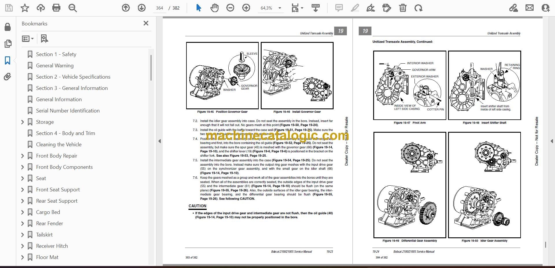
- Section 19 – Reconditioning the MC012C- AS00 Unitized Transaxle with Differential Lock
- General Information
- Transaxle Model and Identification
- Axle Shaft
- Unitized Transaxle Removal
- Unitized Transaxle Disassembly
- Component Disassembly
- Differential Gear Lock Housing Disassembly
- Governor Gear Disassembly
- Differential Gear Case Disassembly
- Shifter Fork Disassembly
- Synchronizer Gear Disassembly
- Intermediate Gear Disassembly
- Idler Shaft Disassembly
- Unitized Transaxle Component Inspection
- Component Assembly
- Idler Shaft Assembly
- Intermediate Gear Assembly
- Synchronizer Gear Assembly
- Shifter Fork Assembly
- Differential Gear Case Assembly
- Governor Gear Assembly
- Differential Gear Lock Housing Assembly
- Unitized Transaxle Assembly
- Unitized Transaxle Installation
- A
- accelerator
- air box
- air filter 14-1
- armature
- axle
- B
- ball bearing
- battery 12-28
- bed, cargo
- belt, drive
- body, front
- brakes
- breather valve (reed valve) 18-9
- C
- camshaft
- camshaft and hydraulic lifter
- carburetor
- cargo bed
- CAUTION
- choke 14-1
- cleaning
- clutch (torque converter) troubleshooting 17-3
- clutch, drive
- clutch, driven
- column, steering
- commutator
- connecting rod
- counterbalance
- counterbalance guide shaft
- counterbalance weight
- crankcase 18-20
- crankshaft
- cylinder block 18-26
- cylinder head 18-4
- cylinder shroud
- D
- DANGER
- dashboard
- differential gear case
- differential lock
- differential lock housing
- diode
- diode, headlight
- drive belt
- drive clutch
- driven clutch
- E
- electrical system
- engine
- engine oil 10-4
- exhaust system 14-1
- F
- fender, front
- fender, rear
- field coil
- fluid, brake 10-4
- flywheel
- forward/reverse
- front body
- fuel filter 14-1
- fuel gauge
- fuel gauge sending unit circuit
- fuel gauge/hour meter
- fuel level sending unit 12-22
- fuel lines 14-1
- fuel pump 14-1, 14-17
- fuel shut-off valve 14-28
- fuel tank
- fueling instructions 10-7
- fuse
- G
- generator circuit
- governor cable
- governor gear
- governor system 16-3, 19-3
- ground straps
- H
- headlight bulb
- headlight diode
- headlight switch
- headlights
- hour meter
- hydraulic lifter
- hydrometer test 11-21
- I
- idler shaft
- ignition
- ignition coil
- inspection
- intake duct
- intermediate gear
- K
- key switch
- kill circuit, engine
- kill wire, engine
- L
- leaf springs, multi 9-1
- lighting circuit
- link rod
- lockout cam
- lockout cam circuit
- low oil warning circuit
- low oil warning light
- lubrication
- M
- maintenance
- master cylinder
- muffler
- N
- O
- oil level sensor
- oil light
- oil pressure relief valve
- oil pump
- oil screen
- oil seal
- oil viscosity 10-7
- oil, engine 10-4
- P
- park brake
- pedal, accelerator
- pedal, brake
- periodic lubrication schedule 10-2
- periodic service schedule 10-1
- piston
- piston and connecting rod
- piston pin
- piston ring
- push rod
- R
- rack and pinion
- receiver hitch
- reed valve
- reverse buzzer
- reverse buzzer circuit
- rocker arm
- rocker arm and push rod
- rocker shaft
- RPM adjustment 14-10
- RPM limiter
- S
- safety
- seat
- serial number, vehicle 3-1
- service schedule
- shifter fork
- shock absorber
- snubber
- solenoid
- spark plug 13-1, 14-1
- specifications
- starter/generator
- starter/generator circuit
- steering
- steering column
- steering wheel
- storage
- suspension, front
- suspension, rear
- synchronizer gear
- T
- test procedure
- test procedures, index of 11-19
- testing
- tire
- torque converter
- torque specifications 18-48
- trailer hitch
- transaxle
- troubleshooting
- U
- V
- valve (cylinder)
- valve guide
- valve seat
- valves (engine)
- voltage limiter
- voltage regulator
- W
- WARNING
- wheel
- wheel cylinder
- wire continuity testing 11-29
- wiring diagram 11-5
Bobcat Software
Bobcat PDF Manuals


