A Bobcat 430 is a tight little mini ex that spends its life trenching, loading trucks, and working right up against foundations. The people who reach for this service manual are the ones lying in the mud with a laptop or binder on the track, trying to get a dead machine back to work. They need the right serial range so the wiring colors, hydraulic layout, and procedures match what's actually in front of them. This manual is for that exact situation on a 430 in the 562911001-562999999 serial range.
What this manual helps you do
- Diagnose no-start or low-power issues on the small diesel, then check fuel and air systems step by step
- Trace hydraulic problems like weak boom, slow travel, or dead auxiliary circuit using the proper test ports and specs
- Follow teardown and reassembly procedures for cylinders, swing motor, drive motors, and control valves on the bench or in the yard
- Troubleshoot electrical faults using wiring diagrams that match this serial range, from dead panel to bad sensors
- Adjust controls, linkages, and track systems after parts replacement so the machine runs straight and responds correctly
Who this is for
This is right for a small contractor, owner-operator, rental fleet, or field tech who is actually repairing a Bobcat 430 within serial numbers 562911001 to 562999999. If you just need operating instructions or daily maintenance tips, you want the operator's handbook instead.
FAQ
Q: Is this a searchable PDF with readable wiring diagrams?
A: Yes, it's typically a searchable PDF and the wiring diagrams are meant to be zoomed in on a screen or printed.
Q: How do I know if it fits my 430?
A: Check your machine's serial plate. If it falls between 562911001 and 562999999, this is the right manual.
Q: Is this the right document if I'm rebuilding or diagnosing, not just changing filters?
A: Yes, this is the workshop-level service manual, meant for real repairs and diagnostics, not basic operation.
If your 430's serial tag lands in that number range and you're planning to wrench on it yourself, this is the manual you want.
📘 Show Index
Table of Contents:
- MAINTENANCE SAFETY
- CONTENTS
- FOREWORD
- FOREWORD
- SAFETY INSTRUCTIONS
- FIRE PREVENTION
- Maintenance
- Operation
- Electrical
- Hydraulic System
- Fueling
- Starting
- Spark Arrester Exhaust System
- Welding And Grinding
- Fire Extinguishers
- SERIAL NUMBER LOCATIONS
- Excavator Serial Number
- Engine Serial Number
- DELIVERY REPORT
- EXCAVATOR IDENTIFICATION
- SAFETY & MAINTENANCE
- LIFTING AND BLOCKING THE EXCAVATOR
- UPPERSTRUCTURE SLEW LOCK
- LIFTING THE EXCAVATOR
- OPERATOR CAB (ROPS / TOPS)
- Description
- Cab Door
- Front Window
- Front Window
- Right Side Window (Early Models)
- Right Side Window (Later Models)
- Heating, Ventilation, and Air Conditioning Duct
- TRANSPORTING THE EXCAVATOR ON A TRAILER
- Loading And Unloading
- Fastening
- TAILGATE
- Opening And Closing The Tailgate
- Adjusting The Latch
- RIGHT SIDE COVER
- SERVICE SCHEDULE
- AIR CLEANER SERVICE
- Daily Check
- Replacing The Filters
- HEATER AIR FILTER (WITH CAB OPTION ONLY)
- ENGINE COOLING SYSTEM
- Cleaning
- Checking Level
- Removing And Replacing Coolant
- FUEL SYSTEM
- Fuel Specifications
- Biodiesel Blend Fuel
- Filling The Fuel Tank
- Removing Water
- Replacing Element
- Draining The Fuel Tank
- Inline Fuel Filter
- Removing Air From The Fuel System
- ENGINE LUBRICATION SYSTEM
- Checking And Adding Engine Oil
- Engine Oil Chart
- Removing And Replacing Oil Filter
- HYDRAULIC SYSTEM
- Checking And Adding Fluid
- Hydraulic Fluid Chart
- Removing And Replacing The Hydraulic Fluid
- Removing And Replacing The Hydraulic Filter
- Removing And Replacing The Case Drain Filter
- Removing And Replacing The Fan Filter
- Diagnostic Couplers
- LUBRICATING THE EXCAVATOR
- TRAVEL MOTOR
- Checking And Adding Oil Level
- Removing And Replacing Oil
- SPARK ARRESTOR MUFFLER
- ENGINE ACCESSORY DRIVE BELT
- Belt Tension
- Belt Adjustment
- SEAT BELT
- Inspection And Maintenance
- PIVOT PINS
- Inspection And Maintenance
- EXCAVATOR STORAGE AND RETURN TO SERVICE
- Storage
- Return To Service
- STOPPING THE ENGINE AND LEAVING THE EXCAVATOR
- Procedure
- Emergency Exits
- MOTION ALARM SYSTEM (IF EQUIPPED)
- Description
- Inspecting
- Adjusting Switch Position
- HYDRAULIC SYSTEM
- HYDRAULIC/HYDROSTATIC SCHEMATICS
- HYDRAULIC SYSTEM INFORMATION
- Glossary Of Hydraulic / Hydrostatic Symbols
- Troubleshooting The Hydraulic Circuit
- Troubleshooting The Cylinder Circuit
- Troubleshooting The Upperstructure Slew Circuit
- BOOM CYLINDER
- Testing
- Removal And Installation
- Parts Identification
- Disassembly
- Assembly
- ARM CYLINDER
- Testing
- Removal And Installation
- Parts Identification
- Disassembly
- Assembly
- BOOM SWING CYLINDER
- Testing
- Removal And Installation
- Parts Identification
- Disassembly
- Assembly
- BUCKET CYLINDER
- Testing
- Removal And Installation
- Parts Identification
- Disassembly
- Assembly
- BLADE CYLINDER
- Testing
- Removal And Installation
- Parts Identification
- Disassembly
- Assembly
- CLAMP CYLINDER
- Testing
- Removal And Installation
- Parts Identification
- Disassembly
- Assembly
- ANGLE BLADE CYLINDER
- Testing
- Removal And Installation
- Parts Identification
- Disassembly
- Assembly
- MAIN RELIEF VALVES
- Testing And Adjusting The Main Relief Valves (S/N 562511001 & Above)
- System Pressures At Gauge Port Specifications
- Testing And Adjusting The Main Relief Valves (S/N 562711001 & Above)
- System Pressures At Gauge Port Specifications
- Testing And Adjusting The Main Relief Valves (S/N 562911001 & Above)
- System Pressures At Gauge Port Specifications
- Testing And Adjusting The Main Relief Valves (S/N 563011001 Above)
- System Pressures At Gauge Port Specifications
- PORT RELIEF VALVES
- Testing And Adjusting Port Relief Valve Pressure
- CROSSPORT RELIEF VALVES
- Testing And Adjusting The Crossport Relief Valves (S/N 562511001 & Above)
- Testing And Adjusting The Crossport Relief Valves (S/N 562711001 & Above)
- Testing And Adjusting The Crossport Relief Valves (S/N 562911001 & Above)
- Testing And Adjusting The Crossport Relief Valves (S/N 563011001 & Above)
- PRESSURE REDUCING VALVE
- ANGLE BLADE VALVE
- Description
- Testing And Adjusting Port Relief Valves
- Testing And Adjusting Sequence Valve
- Removal And Installation
- Parts Identification
- Disassembly
- Assembly
- HYDRAULIC CONTROL VALVE (S/N 562511001 & ABOVE AND 562711001 & ABOVE)
- Removal And Installation
- Parts Identification
- Disassembly And Assembly
- Slew Valve Section Disassembly And Assembly
- Blade Valve Section Disassembly And Assembly
- Boost Valve Section Disassembly And Assembly
- Auxiliary Valve Section Disassembly And Assembly
- Bucket Valve Section Disassembly And Assembly
- Arm Valve Section Disassembly And Assembly
- Mid-Inlet Valve Section Disassembly And Assembly
- Boom Valve Section Disassembly And Assembly
- HYDRAULIC CONTROL VALVE (S/N 562911001 – 562912778)
- Description
- Removal And Installation
- Parts Identification
- Disassembly
- Right Travel Valve Section Disassembly And Assembly
- Left Travel Valve Section Disassembly And Assembly
- Blade Valve Section Disassembly And Assembly
- Slew Valve Section Disassembly And Assembly
- Second Auxiliary Valve Section Disassembly And Assembly
- Bucket Valve Section Disassembly And Assembly
- Arm Valve Section Disassembly And Assembly
- Boom Valve Section Disassembly And Assembly
- Boom Swing Valve Section Disassembly And Assembly
- First Auxiliary Valve Section Disassembly And Assembly
- Inlet Section Disassembly And Assembly
- Assembly
- HYDRAULIC CONTROL VALVE (S/N 562912779 & Above)
- Description
- Removal And Installation
- Parts Identification
- Disassembly
- Right Travel Valve Section Disassembly And Assembly
- Left Travel Valve Section Disassembly And Assembly
- Blade Valve Section Disassembly And Assembly
- Slew Valve Section Disassembly And Assembly
- Auxiliary Valve Section Disassembly And Assembly
- Bucket Valve Section Disassembly And Assembly
- Arm Valve Section Disassembly And Assembly
- Boom Valve Section Disassembly And Assembly
- Boom Swing Valve Section Disassembly And Assembly
- Inlet Section Disassembly And Assembly
- Assembly
- HYDRAULIC CONTROL VALVE (S/N 563011001 – 563012775)
- Description
- Removal And Installation
- Parts Identification
- Disassembly
- Blade Valve Section Disassembly And Assembly
- Slew Valve Section Disassembly And Assembly
- Second Auxiliary Valve Section Disassembly And Assembly
- Bucket Valve Section Disassembly And Assembly
- Arm Valve Section Disassembly And Assembly
- Boom Valve Section Disassembly And Assembly
- Boom Swing Valve Section Disassembly And Assembly
- First Auxiliary Valve Section Disassembly And Assembly
- Inlet Section Disassembly And Assembly
- Assembly
- HYDRAULIC CONTROL VALVE (S/N 563012776 & ABOVE)
- Description
- Removal And Installation
- Parts Identification
- Disassembly
- Blade Valve Section Disassembly And Assembly
- Slew Valve Section Disassembly And Assembly
- Auxiliary Valve Section Disassembly And Assembly
- Bucket Valve Section Disassembly And Assembly
- Arm Valve Section Disassembly And Assembly
- Boom Valve Section Disassembly And Assembly
- Boom Swing Valve Section Disassembly And Assembly
- Inlet Section Disassembly And Assembly
- Assembly
- HYDRAULIC PUMP (S/N 562511001 & ABOVE AND 562711001 & ABOVE)
- Description
- Torque Adjustment
- Testing The Piston Pump
- Testing The Gear Pump
- Testing Auxiliary Flow
- Removal And Installation
- Coupler Removal And Installation
- Hydraulic Pump Start Up
- Gear Pump Parts Identification
- Piston Pump Parts Identification
- Disassembly
- Gear Pump Disassembly
- Gear Pump Assembly
- Piston Pump Disassembly
- Piston Pump Assembly
- Assembly
- HYDRAULIC PUMP (S/N 562911001 & ABOVE AND 563011001 & ABOVE)
- Description
- Torque Adjustment
- Testing The Piston Pump
- Testing The Gear Pump
- Testing Auxiliary Flow
- Removal And Installation
- Coupler Removal And Installation
- Hydraulic Pump Start Up
- Gear Pump Parts Identification
- Piston Pump Parts Identification
- Disassembly
- Gear Pump Disassembly
- Gear Pump Assembly
- Piston Pump Disassembly
- Piston Pump Assembly
- Assembly
- MANIFOLD ASSEMBLY / ACCUMULATOR (S/N 562511001 & ABOVE, 562711001 & ABOVE AND 563011001 & ABOVE)
- Description
- Testing Pilot Pressure
- Removal And Installation
- Parts Identification
- Disassembly
- Assembly
- MANIFOLD ASSEMBLY / ACCUMULATOR (S/N 562911001 & ABOVE)
- Description
- Testing Pilot Pressure
- Removal And Installation
- Parts Identification
- Disassembly
- Assembly
- TRAVEL MOTOR (S/N 562511001 & ABOVE, 562711001 & ABOVE AND 563011001 & ABOVE)
- Removal And Installation
- Parts Identification
- Disassembly
- Assembly
- TRAVEL MOTOR (S/N 562911001 THROUGH 562912751)
- Removal And Installation
- Parts Identification
- Disassembly
- Assembly
- TRAVEL MOTOR (S/N 562912752 & Above)
- Description
- Removal And Installation
- Parts Identification
- Disassembly
- Assembly
- SWIVEL JOINT
- Removal And Installation
- Parts Identification
- Description
- Disassembly
- Assembly
- SWING MOTOR
- Removal And Installation
- Parts Identification
- Disassembly
- Assembly
- SWING MOTOR DRIVE CARRIER
- Removal And Installation
- Parts Identification
- Disassembly
- Assembly
- CONTROL PATTERN SELECTOR VALVE
- Removal And Installation
- Parts Identification
- Disassembly
- Assembly
- RIGHT CONTROL LEVER (JOYSTICK)
- Testing
- Handle Removal And Installation
- Joystick Assembly Removal And Installation
- Parts Identification
- Disassembly
- Assembly
- LEFT CONTROL LEVER (JOYSTICK)
- Testing
- Handle Removal And Installation
- Joystick Assembly Removal And Installation
- Parts Identification
- Disassembly
- Assembly
- TRAVEL CONTROL VALVE (S/N 562511001 & ABOVE, 562711001 & ABOVE AND 563011001 & ABOVE)
- Removal and Installation
- Parts Identification
- Disassembly And Assembly
- TRAVEL CONTROL VALVE (S/N 562911001 & ABOVE)
- Removal And Installation
- Parts Identification
- Disassembly And Assembly
- HOSES
- Hose Guide Location
- Left Control Lever (Joystick) (S/N 562911001 & Above) (Later Models)
- Left Control Lever (Joystick) (S/N 563011001 & Above) (Later Models)
- Right Control Lever (Joystick) (S/N562911001 And Above) (Later Models)
- Right Control Lever (Joystick) (S/N 563011001 & Above) (Later Models)
- Travel Control Valve (S/N 562911001 & Above) (Later Models)
- Travel Control Valve (S/N A563011001 & Above) (Later Models)
- Manifold Assembly / Accumulator (S/N 562911001 & Above) (Later Models)
- Manifold Assembly / Accumulator (S/N 563011001 & Above) (Later Models)
- HYDRAULIC FILTER MOUNT
- HYDRAULIC RESERVOIR
- OIL COOLER
- DIRECT TO TANK VALVE (IF EQUIPPED)
- Removal And Installation
- Parts Identification
- Disassembly And Assembly
- BUILD UP VALVE
- CASE DRAIN FILTER
- COOLING FAN
- Description
- Testing
- Removal And Installation
- Parts Identification
- Disassembly And Assembly
- BOOM SWING LOCK VALVE
- Description
- Removal And Installation
- Parts Identification
- Disassembly
- Assembly
- HYDRAULIC X-CHANGE™ VALVE
- Removal And Installation
- Parts Identification
- Disassembly
- Assembly
- HYDROSTATIC SYSTEM
- HYDROSTATIC SYSTEM INFORMATION
- Troubleshooting Chart
- Relief / Replenishing Valve Function
- Relief / Replenishing Valve Location
- Relief / Replenishing Valve Removal And Installation
- Charge Pressure Relief Valve Removal And Installation
- TRAVEL PILOT PRESSURE
- HYDROSTATIC PUMP
- Removal And Installation
- Fan / Charge Pump Parts Identification
- Fan / Charge Pump Disassembly And Assembly (S/N 562511001 & Above And 562711001 & Above)
- Parts Identification (Front) (S/N 562511001 & Above, 562711001 & Above And 563111001 & Above)
- Parts Identification (Rear) (S/N 562511001 & Above And 562711001 & Above)
- Parts Identification (Rear) (S/N 563011001 & Above)
- Disassembly
- Inspection
- Assembly
- Hydrostatic Pump StartUp
- FAN / CHARGE PUMP
- Description (S/N 562511001 & Above And 562711001 & Above)
- Testing
- DRIVE BELT SHIELD
- DRIVE BELT
- Adjustment
- Removal And Installation
- UNDERCARRIAGE
- BLADE
- ANGLE BLADE ASSEMBLY
- ANGLE BLADE
- ANGLE BLADE CUTTING EDGE
- TRACKS
- Track Lug Height
- Rubber Track Clearance
- Steel Track Clearance
- Adjustment
- Rubber Track Removal And Installation
- Steel Track Removal And Installation
- TRACK FRAME
- Disassembly And Assembly
- Recoil Spring Cylinder Disassembly And Assembly (W / O Replaceable Shaft)
- Recoil Spring Cylinder Parts Identification (With Replaceable Shaft)
- Recoil Spring Cylinder Disassembly And Assembly (With Replaceable Shaft)
- TRACK DAMAGE IDENTIFICATION
- Cutting Of Steel Cords
- Abrasion Of Embedded Metals
- Separation Of Embedded Metals
- Separation Of Embedded Metals Due To Corrosion
- Cuts On The Lug Side Rubber
- Cracks On The Lug Side Rubber Due To Fatigue
- Lug Abrasion
- Cracks And Cuts On The Lug Side Rubber
- Abrasion Of The Track Roller Side
- Cuts On The Edges Of Track Roller Side
- TRACK IDLER
- Parts Identification
- Disassembly
- Assembly
- UPPER TRACK ROLLER
- Parts Identification
- Disassembly
- Assembly
- LOWER TRACK ROLLER
- Parts Identification
- Disassembly
- Assembly
- SWING CIRCLE GEAR
- Swing Bearing Removal
- Swing Bearing Installation
- UPPERSTRUCTURE & SWING SECTION
- UPPERSTRUCTURE
- ROPS CANOPY
- CAB
- Removal And Installation
- Front Window Removal And Installation
- Right Side Rear Sliding Window Removal And Installation
- Right Side Front Sliding Window Removal And Installation
- Right Side Front And Rear Sliding Window Weather Strip Removal And Installation
- Right Side Front And Rear Sliding Window Wiper Strip Removal And Installation
- Glass Removal
- Glass Installation
- SEAT AND SEAT MOUNT
- RIGHT CONSOLE
- Console Cover Removal And Installation
- Console Base Removal And Installation
- LEFT CONSOLE
- Lower Console Cover Removal And Installation
- Upper Console Cover Removal And Installation
- Compression Spring Removal And Installation
- Compression Spring Disassembly And Assembly
- Lock Lever Removal And Installation
- Console Removal And Installation
- Disassembly And Assembly
- Console Switch Removal And Installation
- Console Base Removal And Installation
- ENGINE SPEED CONTROL
- Removal And Installation
- Disassembly And Assembly
- Adjustment (Later Models)
- BLADE CONTROL
- Lever Removal And Installation
- Linkage Removal And Installation
- Linkage Disassembly And Assembly
- Control Cable Removal And Installation
- RIGHT PEDAL AND LINKAGE
- Pedal Removal And Installation
- Pedal Disassembly And Assembly
- Control Cable Removal And Installation
- TRAVEL CONTROLS
- Removal And Installation
- Disassembly And Assembly
- Adjustment
- CONTROL LINKAGE ASSEMBLY
- FLOOR MAT AND FLOOR PLATES
- FUEL TANK
- HORN
- Removal And Installation (Earlier Models)
- Removal And Installation (Later Models)
- SWING FRAME
- Boom Swing Bracket Removal And Installation
- Boom Swing Bracket Hose Installation
- Bushing Removal
- Bushing Installation
- BOOM
- ARM
- Removal And Installation
- Arm To Boom Bushing Removal And Installation
- Arm To Bucket And Bucket Link Bushing Removal And Installation
- BUCKET
- Bucket Teeth Removal And Installation
- Bucket Side Cutting Edge Removal And Installation
- CLAMP
- TAILGATE
- X-CHANGE™
- Removal And Installation
- Parts Identification
- Disassembly
- Assembly
- Check Proper Latch Engagement
- X-CHANGE™ (HYDRAULIC)
- Removal And Installation
- Parts Identification
- Disassembly
- Assembly
- UPPERSTRUCTURE SLEW LOCK
- Removal And Installation
- Disassembly And Assembly
- RIGHT SIDE COVER
- COUNTERWEIGHT
- ELECTRICAL SYSTEM & ANALYSIS
- ELECTRICAL SCHEMATICS
- ELECTRICAL SYSTEM INFORMATION
- Troubleshooting Chart
- Description
- Fuse And Relay Location
- BATTERY
- Servicing
- Removing And Installing The Battery
- Using A Booster Battery (Jump Starting)
- ALTERNATOR
- Engine Accessory Drive Belt
- Removal And Installation
- Alternator Identification
- Charging System Check
- Alternator Voltage Test
- Low Voltage Test
- High Voltage Test
- Rectifier Continuity (Diode) Test
- Alternator Regulator Test
- Parts Identification
- Disassembly
- Stator Continuity Test
- Stator Ground Test
- Rotor Continuity Test
- Rotor Ground Test
- Assembly
- STARTER
- Removal And Installation
- Parts Identification
- Disassembly
- Inspection And Repair
- Assembly
- LIGHTS
- Removal And Installation
- Boom Light Removal and Installation (Earlier Models)
- Boom Light Removal and Installation (Later Models)
- Boom Light Bulb Replacement (Later Models)
- TWO SPEED SWITCH
- FUEL LEVEL SENDER
- Removal And Installation
- Testing
- DIAGNOSTIC SERVICE CODES
- DELUXE INSTRUMENT PANEL SETUP
- Passwords
- Password Entry (For Starting and Operating the Machine)
- Changing The Owner or Operator Password
- Password Lockout Feature
- Job Clock
- RPM
- ENGINE SERVICE
- TROUBLESHOOTING
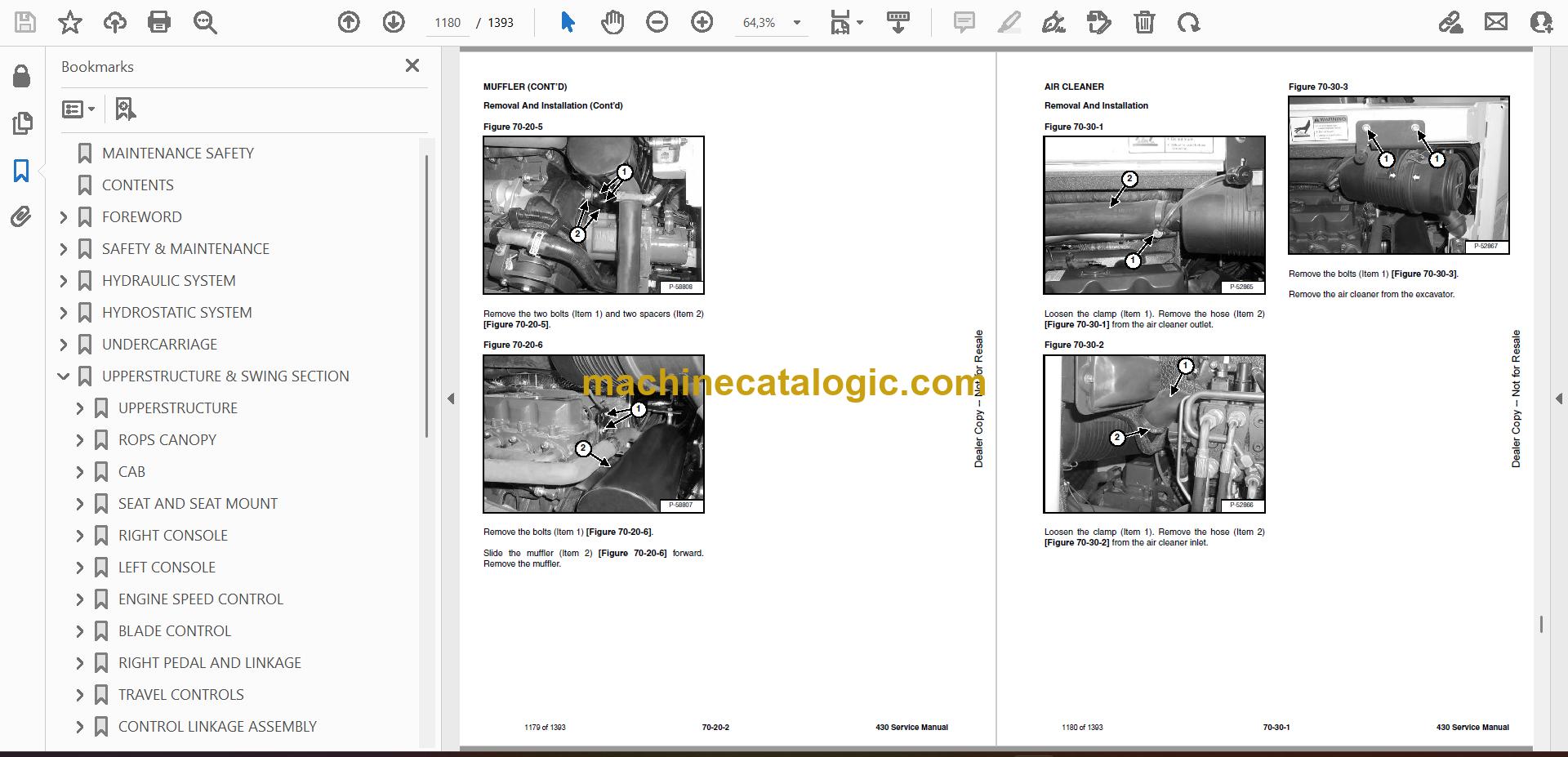
- MUFFLER
- AIR CLEANER
- RADIATOR
- ENGINE COMPONENTS AND TESTING
- Engine Compression Checking
- Glow Plug Removal And Installation
- Checking The Glow Plug
- Fuel Shut-off Solenoid Removal And Installation
- Fuel Injection Pump Check
- Fuel Injection Pump Removal And Installation
- Fuel Injection Pump Timing
- Fuel Injector Nozzles Removal And Installation
- Fuel Injector Nozzle Check
- Valve Clearance Adjustment
- ENGINE
- ENGINE FLYWHEEL (EARLY MODELS)
- Removal And Installation
- Removal And Installation
- Flywheel Ring Gear
- ENGINE FLYWHEEL (LATER MODELS)
- Removal And Installation
- Hydraulic Pump Coupler
- Flywheel Ring Gear
- RECONDITIONING THE ENGINE
- Cylinder Head Removal And Installation
- Cylinder Head Disassembly And Assembly
- Cylinder Head Servicing
- Cylinder Head Top Clearance
- Valve Guide Checking
- Reconditioning The Valve And Valve Seat
- Valve Spring
- Rocker Arm And Shaft Checking
- Timing Gearcase Cover Removal And Installation
- Idler Gear And Camshaft Removal And Installation
- Camshaft Servicing
- Idler Gear And Shaft Servicing
- Timing Gears Checking Backlash
- Fuel Camshaft Removal And Installation
- Fuel Camshaft Governor
- Crankshaft Gear Removal And Installation
- Oil Pump Removal And Installation
- Oil Pump Service
- Checking Engine Oil Pressure
- Valve Tappets
- Piston And Connecting Rod Removal And Installation
- Piston And Connecting Rod Servicing
- Connecting Rod Alignment
- Crankshaft And Bearings Removal And Installation
- Crankshaft And Bearings, Servicing
- Cylinder Bore, Checking
- Water Pump Removal And Installation
- Water Pump Disassembly And Assembly
- HEATING, VENTILATION, AIR CONDITIONING
- HEATER COIL (EARLY MODELS)
- Removal And Installation With A/C
- Removal And Installation Without A/C
- HEATER COIL (LATER MODELS)
- Removal And Installation With A/C
- Removal And Installation Without A/C
- BLOWER FAN (EARLY MODELS)
- Removal And Installation
- Disassembly And Assembly
- BLOWER FAN (LATER MODELS)
- Removal And Installation
- Disassembly And Assembly
- Resistor Removal And Installation
- HEATER VALVE
- AIR CONDITIONING SYSTEM FLOW
- COMPONENTS
- SAFETY
- REGULAR MAINTENANCE
- Heater Air Filter
- Engine Accessory Drive Belt
- Cleaning The Condenser
- BASIC TROUBLESHOOTING (EARLY MODELS)
- Poor A/C Performance
- Cleaning The A/C Evaporator Coil And Heater Coil
- Engine Accessory Drive Belt
- Checking The Electrical System
- Engine Coolant By-Passing The Heater Valve
- BASIC TROUBLESHOOTING (LATER MODELS)
- Poor A/C Performance
- Cleaning The A/C Evaporator Coil And Heater Coil
- Engine Accessory Drive Belt
- Checking The Electrical System
- Engine Coolant By-Passing The Heater Valve
- GENERAL AIR CONDITIONING SERVICE GUIDELINES
- Compressor Oil
- Compressor Oil Check
- Component Replacement And Refrigeration Leaks
- SYSTEM TROUBLESHOOTING CHART
- Blower Motor Does Not Operate
- Gauge Pressure Related Troubleshooting
- TEMPERATURE / PRESSURE
- AIR CONDITIONING SERVICE
- SYSTEM CHARGING AND RECLAMATION
- Reclamation Procedure
- Charging Procedure With A Manifold Gauge Set
- COMPRESSOR
- Removal And Installation
- Compressor Clutch Disassembly And Assembly
- CONDENSER
- RECEIVER / DRIER
- PRESSURE RELIEF VALVE
- PRESSURE SWITCH
- EVAPORATOR / HEATER UNIT (EARLY MODELS)
- Removal And Installation
- Disassembly And Assembly
- EVAPORATOR/HEATER UNIT (LATER MODELS)
- Removal And Installation
- Disassembly And Assembly
- THERMOSTAT (EARLY MODELS)
- THERMOSTAT (LATER MODELS)
- EXPANSION VALVE (EARLY MODELS)
- EXPANSION VALVE (LATER MODELS)
- EVAPORATOR (EARLY MODELS)
- EVAPORATOR (LATER MODELS)
- SPECIFICATIONS
- EXCAVATOR SPECIFICATIONS
- Excavator Dimensions With Standard Arm, Long Arm Option and Extendable Arm Kit
- Excavator Standard Arm Machine Dimensions
- Excavator Long Arm Machine Dimensions
- Excavator Extendable Arm Machine Dimensions
- Excavator With Optional Angle Blade Dimensions
- Performance (S/N 56251101 & Above And 562711001 & Above)
- Performance (S/N 562911001 & Above)
- Performance (S/N 563011001 & Above)
- Controls
- Engine
- Hydraulic System
- Hydraulic Cylinders (S/N 562511001 & Above And S/N 562711001 & Above)
- Hydraulic Cylinders (S/N 562911001 & Above And S/N 563011001 & Above)
- Hydraulic Cycle Times
- Electrical
- Undercarriage
- Capacities
- Fuel Tank
- Tracks
- Type
- Drive System (S/N 562511001 & Above, 562711001 & Above And 563011001 & Above)
- Drive System (S/N 562911001 & Above)
- Slew System
- Ground Pressure (S/N 562511001 & Above)
- Ground Pressure (S/N 562711001 & Above, 562911001 & Above And 563011001 & Above)
- ENGINE SPECIFICATIONS
- Specifications
- Crankshaft Re-Grind Data
- TORQUE SPECIFICATIONS
- Torque for General SAE Bolts
- Torque For General Metric Bolts
- HYDRAULIC CONNECTION SPECIFICATIONS
- O-ring Face Seal Connection
- Straight Thread O-ring Fitting
- Tubelines And Hoses
- Flare Fitting
- O-ring Flare Fitting
- Port Seal Fitting
- HYDRAULIC FLUID SPECIFICATIONS
- FUEL, COOLANT AND LUBRICANTS
- CONVERSIONS
- Decimal And Millimeter Equivalents Chart
- U.S. To Metric Conversion Chart
- SERVICE TOOLS REQUIRED
- Remote Start Tools
- Hydraulic Tools
- Engine Tools
- HVAC Tools
- ALPHABETICAL INDEX
Bobcat Software
Bobcat PDF Manuals


