$ 0
0
$ 0
0

Bobcat 220 Excavator Service Manual (SN 508215001-508299999)

Format: PDF (Printable Document)

File Language: English

File Pages: 299

File Size: 14.53 MB (Speed Download Link)

Brand: Bobcat

Model: 220 Excavator

Book No: 6722345

Serial No: SN 508215001-508299999

Type of Document: Service Manual

Categories: ,

$ 45

Share:

Bobcat 220 Excavator Service Manual (SN 508215001-508299999)

When a little 220 excavator is your only digger on the place, it ends up doing everything from trenching water lines to cleaning ditches and loading brush. The service manual is what you grab when a hose blows on Saturday, the swing motor starts leaking, or the engine loses power and you've only got a weekend to sort it out. It's written for people who actually turn wrenches and need the right sequence, specs, and diagrams so they only tear it apart once. If your machine falls in the serial range, this is the book you use to keep it alive.

What this manual helps you do

  • Diagnose hydraulic problems, trace oil flow, and check pressures on the 220's working circuits
  • Follow teardown and reassembly steps for cylinders, pumps, motors, and final drives
  • Troubleshoot electrical issues using wiring diagrams and connector callouts
  • Set linkages, controls, and travel functions after repairs so the machine behaves correctly
  • Verify engine-related repairs on the small diesel, from fuel system work to basic top-end jobs

Who this is for

This is for a 220 excavator owner, small contractor, field tech, or shop mechanic working on machines in serial range 508215001 through 508299999. If you just need operating tips, safety info, or maintenance intervals, you want the operator's handbook instead, not this service manual.

FAQ

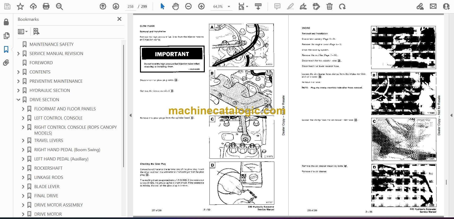
Q: Is this a searchable PDF, and can I read the wiring diagrams clearly?

A: Yes, it's a PDF, and in my experience these scan well enough to zoom in on wiring and hydraulic schematics on a laptop or tablet.

Q: How do I know if it fits my exact 220?

A: Check your serial plate. If your 220's serial number falls between 508215001 and 508299999, this is the right manual.

Q: Is this the right document if I'm rebuilding or diagnosing, not just changing oil?

A: Yes, this is the workshop-level service manual, meant for real repair work, not routine greasing and inspections.

Bottom line: If you own a Bobcat 220 in that serial range and plan to fix or diagnose it yourself, this is the manual you want.

📘 Show Index

Table of Contents:

  • MAINTENANCE SAFETY
  • SERVICE MANUAL REVISION
    • 220-1
  • FOREWORD
  • CONTENTS
    • SAFETY INSTRUCTIONS
    • SERIAL NUMBER LOCATIONS
    • HYDRAULIC EXCAVATOR SERIAL NUMBER
    • ENGINE SERIAL NUMBER
    • DELIVERY REPORT
    • HYDRAULIC EXCAVATOR IDENTIFICATION
  • PREVENTIVE MAINTENANCE
    • SERVICE SCHEDULE
    • ENGINE COVER
    • AIR CLEANER SERVICE
    • FUEL SYSTEM
      • Fuel System Service
      • Fuel Filter
      • Removing Air From The Fuel System
    • ENGINE LUBRICATION SYSTEM
      • Engine Oil And Filter Replacement
    • COOLING SYSTEM
      • Coolant Level
      • Coolant Replacement
    • HYDRAULIC SYSTEM
      • Checking And Adding Fluid
      • Diagnostic Couplers
      • Replacement Of The Hydraulic Filter
      • Hydraulic Reservoir
      • Replacement fo the Hydraulic Fluid
    • USING A BOOSTER BATTERY (JUMP STARTING)
      • Procedure
    • LUBRICATION OF THE HYDRAULIC EXCAVATOR
      • Procedure
  • HYDRAULIC SECTION
    • HYDRAULIC SCHEMATICS
    • HYDRAULIC SYSTEM TROUBLESHOOTING
    • HYDRAULIC SERVICE INFORMATION
      • Description
      • Checking the Main Relief Valves
    • HYDRAULIC PUMPS
      • Removal And Installation
    • HYDRAULIC PUMP ASSEMBLY
      • Disassembly
      • Assembly
    • HYDRAULIC CONTROL VALVE (6-Spool)
      • Removal And Installation
      • 6 Spool Control Valve Assembly
      • Disassembly and Assembly
      • Disassembly
      • Inlet Section (R.H. and L.H. Travel)
        • Disassembly
        • Assembly
      • Valve Sections (Boom, Bucket & Arm)
        • Disassembly
        • Assembly
      • Valve Sections (Auxiliary)
        • Disassembly
        • Assembly
      • Port Relief Valve
        • Disassembly
        • Assembly
        • Adjustment Procedure
      • Main Relief Valve
        • Disassembly
        • Assembly
        • Adjustment Procedure
    • HYDRAULIC CONTROL VALVE (3 Spool)
      • Removal and Installation
      • 3 Spool Control Valve Assembly
      • Disassembly
      • INLET SECTION (Housing Swing)
        • Disassembly
        • Assembly
      • END COVER (Boom Swing) and VALVE SECTION (Blade)
        • Disassembly
        • Assembly
      • Load Check Block
        • Disassembly
        • Assembly
      • Build-up Valve
        • Assembly
      • Main Relief Valve
        • Disassembly
        • Assembly
        • Adjustment Procedure
    • BOOM CYLINDER
      • Removal And Installation
      • Boom Shield
      • Boom Cylinder
    • DIPPERARM CYLINDER
      • Removal And Installation
    • BUCKET CYLINDER
      • Removal And Installation
    • BLADE CYLINDER
      • Removal And Installation
    • BOOM SWING CYLINDER
      • Removal And Installation
    • HYDRAULIC CYLINDER
      • Disassembly
      • Assembly
    • HYDRAULIC FILTER ASSEMBLY
      • Removal and Installation
    • AUXILIARY COUPLERS
    • JOYSTICK MANIFOLD WITH ACCUMULATOR
      • Removal And Installation
      • Disassembly And Assembly
    • DRAIN BLOCK
      • Removal And Installation
      • Filter Screen
      • Drain Block
    • OIL COOLER
    • JOYSTICK CONTROL CHANGE
  • DRIVE SECTION
    • FLOORMAT AND FLOOR PANELS
      • Removal And Installation
    • LEFT CONTROL CONSOLE
      • Microswitch Adjustment Procedure
      • Lockout Microswitch Removal and Installation
      • Console Cover Removal and Installation
      • Joystick Removal And Installation
      • Removal And Installation
      • Fuel Tank Removal and Installation
      • Lock Lever Removal And Installation
      • Lock Lever Adjustment Procedure
      • Latch Hook Removal and Installation
      • Gas Spring Removal And Installation
      • Upper Console Removal And Installation
    • RIGHT CONTROL CONSOLE (ROPS CANOPY MODELS)
      • (CAB MODELS)
      • Console Cover Removal And Installation
      • Joystick Removal And Installation
      • Control Console Removal And Installation
      • Hydraulic Tank Removal And Installation
    • TRAVEL LEVERS
      • Removal And Installation
    • RIGHT HAND PEDAL (Boom Swing)
      • Removal And Installation
    • LEFT HAND PEDAL (Auxiliary)
      • Removal And Installation
    • ROCKERSHAFT
      • Removal And Installation
    • LINKAGE RODS
      • Removal And Installation
    • BLADE LEVER
      • Removal And Installation
    • FINAL DRIVE
      • Removal And Installation
    • DRIVE MOTOR ASSEMBLY
      • Parts Identification
    • DRIVE MOTOR
      • Disassembly
      • Assembly
      • Check Oil Level
      • Draining Final Drive Case
    • JOYSTICK
      • Parts Identification
      • Disassembly And Assembly
  • UPPER WORKS AND SWING SECTION
    • SWING MOTOR
      • Testing The Cross Port Reliefs
      • Start The Engine
      • Removing The Cross Port Reliefs
      • Removal And Installation
      • Disassembly
      • Assembly
      • Motor Timing
    • UPPER WORKS
      • Removal And Installation
      • Installation
    • CENTER SWIVEL JOINT
      • Removal and Installation
      • Disassembly and Assembly
    • SWING CIRCLE GEAR
      • Removal And Installation
    • ROPS CANOPY
      • Removal And Installation
    • CAB
      • Removal And Installation
  • MAIN FRAME AND TRACKS
    • ENGINE COVER
      • Removal And Installation
    • SEAT AND MOUTING FRAME
      • Removal And Installation
    • SEAT MOUNT
      • Removal And Installation
    • SPEED LEVER
      • Removal And Installation
    • SWING LOCK LEVER AND PIN
      • Removal And Installation
    • BUCKET
      • Removal And Installation
      • Installation
    • ARM
      • Removal And Installation
    • BOOM
      • Removal And Installation
    • SWING POST
      • Removal And Installation
      • Bushing Replacement
    • TRACK
      • Track Tension Adjustment
      • Removal And Installation
      • Damage Identification And Causes
    • TRACK IDLER
      • Parts Identification
      • Disassembly
      • Assembly
    • TRACK ROLLER
      • Parts Identification
      • Disassembly
      • Assembly
      • Disassembly
  • ELECTRICAL SYSTEM
    • ELECTRICAL SCHEMATICS
    • 6 ELECTRICAL SYSTEM
      • TROUBLESHOOTING
    • ELECTRICAL SYSTEM
      • Description
      • Fuse
      • Electrical System Service
    • BATTERY
      • Checking The Battery
      • Removal And Installation
    • ALTERNATOR
      • Checking The Alternator Output
      • Belt Adjustment
      • ELECTRICAL CONNECTION
      • Removal And Installation
      • Disassembly And Assembly
      • Checking Rotor, Stator And Rectifier
    • STARTER
      • Removal And Installation
      • Disassembly And Assembly
      • Cleaning And Inspection
    • HORN
      • Removal And Installation
    • FUEL LEVEL SENDOR
      • Removal And Installation
  • ENGINE SERVICE
    • 7 ENGINE SERVICE
    • TROUBLESHOOTING
    • VALVE CLEARANCE
      • Adjustment
    • ENGINE COMPRESSION
      • Checking
    • FUEL FILTER
      • Element
      • Removing Air From The Fuel System
      • Fuel Filter Assembly Removal And Installation
    • FUEL INJECTION PUMP
      • Checking The Injection Pump
      • Removal And Installation
      • Timing The Injection Pump
    • FUEL INJECTOR NOZZLES
      • Removal And Installation
      • Checking The Injector Nozzle
    • GLOW PLUGS
      • Removal And Installation
      • Checking The Glow Plug
    • ENGINE
      • Removal And Installation
    • SPARK ARRESTOR MUFFLER
      • Removal And Installation
    • RADIATOR
      • Checking The Radiator And Radiator Cap
      • Removal And Installation
    • ENGINE FLYWHEEL
      • Removal And Installation
      • Hydraulic Pump Coupler
      • Flywheel Ring Gear
    • CYLINDER HEAD
      • Removal Of The Cylinder Head
      • Disassembly Of The Cylinder Head
      • Servicing The Cylinder Head And Valves
      • Checking Valve Springs
      • Checking Rocker Arm And Shaft
      • Assembling The Cylinder Head
      • Installing The Cylinder Head
    • TIMING GEAR COVER
      • Removal And Installation
    • TIMING GEAR, CAMSHAFT AND OIL PUMP
      • Removal And Installation
      • Oil Pump Service
      • Servicing The Camshaft
    • CRANKSHAFT AND PISTONS
      • Removal And Installation
      • Crankshaft Service
      • Servicing The Connecting Rods And Pistons
    • CYLINDER LINERS
      • Checking The Cylinder Liners
      • Cylinder Liner Installation
    • WATER PUMP
      • Removal And Installation
      • Disassembly And Assembly
  • TECHNICAL DATA
    • HYDRAULIC EXCAVATOR SPECIFICATIONS
      • Machine Dimensions
      • Lifting Capacity With Blade Off Ground
      • PERFORMANCE & OPERATION
      • ENGINE
      • HYDRAULIC SYSTEM
      • SWING SYSTEM
      • HYDRAULIC CYLINDERS
      • DRIVE SYSTEM
      • BRAKES
      • UNDERCARRIAGE
      • TRACK
      • CAPACITIES
      • DIGGING FORCE
    • ENGINE SPECIFICATIONS (KUPOTA)
      • Engine
      • Fuel Injector Nozzles
      • Fuel Injection Pump
      • Cylinder Head
      • Valves
      • Valve Springs
      • Rocker Arms
      • Camshaft
      • Cylinders
      • Piston Rings
      • Pistons
      • Crankshaft
      • Oil Pump
      • Thermostat
      • ENGINE TORQUE
      • Re-Grinding The Crankshaft
    • FUEL, COOLANT AND LUBRICANTS
    • OIL SPECIFICATIONS

Bobcat Software

Bobcat PDF Manuals

Related Manuals

0
    0
    Your Cart
    Your cart is emptyReturn to Shop