The Bobcat 2200 is basically your farm, acreage, or plant-runabout machine, hauling tools, seed, guys, and light materials where a skid steer or CTL would be overkill. The people who reach for this service manual are the ones actually wrenching on it: small contractors, farm shops, rental yards, or a tech who usually works on Deere Gators or Cat utility stuff and now has a Bobcat 2200 in the bay. They're trying to sort no-starts, drivetrain issues, steering and brake problems, and electrical gremlins without guessing.
What this manual helps you do
- Diagnose no-start, hard-start, and poor running using step-by-step checks instead of just throwing ignition or fuel parts at it
- Trace and repair wiring and charging problems using proper diagrams and connector callouts
- Check and adjust steering, suspension, and brakes after parts replacement so the machine tracks straight and stops right
- Follow teardown and reassembly procedures on driveline components, hubs, and related mechanical assemblies
- Verify fluid types and service intervals when you're doing full services on a used or ex-rental machine
Who this is for
This manual is for anyone working on a Bobcat 2200 Utility Vehicle in the serial range A5A011001 to A5A099999 and needs real repair procedures, not just safety stickers and basic checks. If you only want to learn how to drive it or do simple daily checks, you want the operator's handbook instead, not this shop manual.
FAQ
Q: Is this a searchable PDF and can I read the wiring diagrams clearly?
A: Yes, these manuals are usually searchable PDFs and the wiring diagrams are laid out so you can zoom in and read pin labels and wire colors.
Q: How do I know if my machine is covered?
A: Check your Bobcat 2200 serial number plate. If it falls between A5A011001 and A5A099999, this is the right manual.
Q: Is this the right document if I'm doing real repairs, not just maintenance?
A: Yes, this is the workshop-level service manual, the one you'd use for diagnostics and component repair.
Bottom line, if your 2200's serial number falls in that range and you're actually turning wrenches on it, this is the manual you want. If you're just operating it, it's overkill.
📘 Show Index
Table of Contents:
- Section 1 – Safety
- Section 2a – Vehicle Specifications: Honda Gas & Kubota Diesel Powered
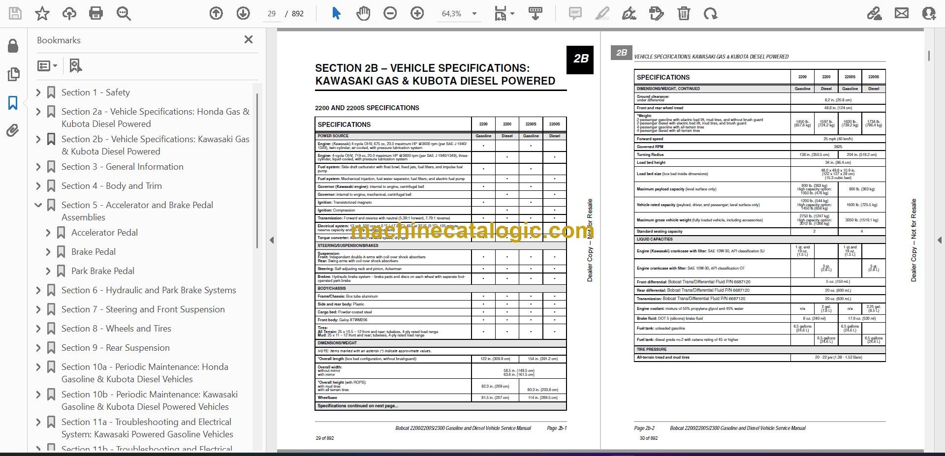
- 2200 and 2200S Specifications
- 2300 Specifications
- Section 2b – Vehicle Specifications: Kawasaki Gas & Kubota Diesel Powered
- 2200 and 2200S Specifications
- 2200 Homologated Specifications
- 2300 Specifications
- Section 3 – General Information
- General Information
- Model Identification
- Engine Serial Number Locations
- Gasoline EngineS
- Diesel Engine
- Storage
- Preparing the Vehicle for Extended Storage
- Returning the Stored Vehicle to Service
- Using A Booster Battery (Jump Starting)
- Section 4 – Body and Trim
- Cleaning the Vehicle
- Front Body Repair
- Light Scratches
- Abrasions and Haze
- Large Scratches and Abrasions
- Front Body Components
- Instrument Panel Removal
- Instrument Panel Installation
- Front Fascia Removal
- Front Fascia Installation
- Hood Removal
- Hood Installation
- Center Cowl Panel Removal
- Center Cowl Panel Installation
- Side Cowl Panel (Fender) Removal
- Side Cowl Panel (Fender) Installation
- Front Fender Flare Removal
- Front Fender Flare Installation
- Roll-Over Protective Structure (ROPS)
- ROPS Removal
- ROPS Installation
- Seat
- Seat Removal
- Seat Adjustment
- Seat Installation
- Seat Support Removal
- Seat Support Installation
- Safety Belts
- Safety Belt Removal
- Safety Belt Installation
- Cargo Bed – Electric Lift
- Testing the Bed Lift Motor
- Bed Lift Motor Removal
- Bed Lift Motor Installation
- Cargo Bed Removal
- Cargo Bed Installation
- Cargo Bed – Manual Lift
- Cargo Bed Removal
- Cargo Bed Installation
- Rear Fender
- Rear Fender Removal
- Rear Fender Installation
- Floor Mat
- Floor Mat Removal
- Floor Mat Installation
- Section 5 – Accelerator and Brake Pedal Assemblies
- Accelerator Pedal
- Accelerator Pedal Removal
- Accelerator Pedal Installation
- Accelerator Pedal and RPM Adjustment
- Brake Pedal
- Brake Pedal Removal
- Brake Pedal Installation
- Brake Pedal Adjustment
- Park Brake Pedal
- Park Brake Pedal Assembly Removal
- Park Brake Pedal Assembly Installation
- Section 6 – Hydraulic and Park Brake Systems
- Brake System Inspection
- Brake System Troubleshooting
- Brake Pads and Caliper
- Front Brake Pad and Caliper Removal
- Front Brake Pad and Caliper Installation
- Rear Brake Pad and Caliper Removal
- Rear Brake Pad and Caliper Installation
- Brake Disc and Hub
- Front Wheel Disc and Hub Removal
- Front Wheel Disc and Hub Installation
- Rear Wheel Disc Removal
- Rear Wheel Disc Installation
- Hydraulic Line Replacement
- Front Brake Line Removal
- Front Brake Line Installation
- Rear Brake Line Removal
- Rear Brake Line Installation
- Master Cylinder and Reservoir
- Filling the Hydraulic System
- Reservoir Removal
- Reservoir Installation
- Master Cylinder Removal
- Master Cylinder Installation
- Bleeding the Hydraulic Brake System
- Bleeding Brakes on a DOT 5 Fluid Filled System
- Purging the Hydraulic System
- Park Brake System
- Park Brake Adjustment
- Park Brake Cable Adjustment
- Park Brake Wheel Cables
- Front Park Brake Cable Removal
- Front Park Brake Cable Installation
- Park Brake Equalizer Removal
- Park Brake Equalizer Installation
- Section 7 – Steering and Front Suspension
- Steering Wheel
- Steering Wheel Removal
- Steering Wheel Installation
- Steering Column
- Steering Column Removal
- Steering Column Installation
- Rack and Pinion
- Rack and Pinion Removal
- Rack and Pinion Installation
- Rack and Pinion Disassembly
- Rack and Pinion Assembly
- Front Suspension
- Front Suspension Components
- Steering Upright Removal
- Upper A-Arm Removal
- Upper A-Arm Installation
- Lower A-Arm Removal
- Lower A-Arm Installation
- Front Coil-Over Shock Absorber Removal
- Front Coil-Over Shock Absorber Installation
- Steering Upright Installation
- Section 8 – Wheels and Tires
- General Information
- Wheels
- Wheel Removal
- Wheel Installation
- Tires
- Tire Removal
- Tire Installation
- Section 9 – Rear Suspension
- Rear Coil-Over Shock Absorber
- Swing Arms
- Swing Arm Removal
- Swing Arm Installation
- Section 10a – Periodic Maintenance: Honda Gasoline & Kubota Diesel Vehicles
- Periodic Service Schedule
- Periodic Lubrication Schedule – 2200
- Periodic Lubrication Schedule – 2300
- Lubricating The Attachment Arm And Interface
- Brake Fluid Reservoir
- Engine Oil
- Oil Pressure – Gasoline Engine
- Engine Oil Level Check
- Engine Oil and Filter Change
- Oil Viscosity
- Gearcase Lubrication
- Lubrication Level Check for Front Differential, Transmission, and Rear Differential
- Lubrication Change for Front Differential, Transmission, and Rear Differential
- Hydraulic System – 2300 Vehicle
- Engine Coolant – Diesel Vehicles
- Engine Coolant Level Check
- Fueling Instructions
- Draining Water from Fuel Filter
- Battery
- Section 10b – Periodic Maintenance: Kawasaki Gasoline & Kubota Diesel Powered Vehicles
- Periodic Service Schedule
- Periodic Lubrication Schedule – 2200
- Lubricating The Attachment Arm And Interface
- Brake Fluid Reservoir
- Engine Oil
- Oil Pressure – Gasoline Engine
- Engine Oil Level Check
- Engine Oil and Filter Change
- Oil Viscosity
- Spark Plugs
- Spark Plug Cleaning And Inspection
- Spark Plug Gap Inspection
- Gearcase Lubrication
- Lubrication Level Check for Front Differential, Transmission, and Rear Differential
- Lubrication Change for Front Differential, Transmission, and Rear Differential
- Hydraulic System – 2300 Vehicle
- Engine Coolant – Diesel Vehicles
- Engine Coolant Level Check
- Fueling Instructions
- Draining Water from Fuel Filter
- Battery
- Section 11a – Troubleshooting and Electrical System: Kawasaki Powered Gasoline Vehicles
- Troubleshooting Guide
- Wiring Diagram
- Test Procedures
- Section 11b – Troubleshooting and Electrical System: Honda Powered Gasoline Vehicles
- Troubleshooting Guide
- Wiring Diagram
- Test Procedures
- Section 11c – Troubleshooting and Electrical System: Diesel Vehicles
- Troubleshooting Guide
- Wiring Diagram
- Test Procedures
- Section 12a – Electrical Components: Kawasaki Powered Gasoline Vehicles
- Starter and Starter Solenoid
- Relays
- Neutral Switch
- Carburetor Solenoid
- Carburetor Heater
- Voltage Regulator
- Warning Lights
- Fuel Gauge/Hour Meter
- Key Switch
- 12-Volt Accessory Receptacle
- Bed Lift Switch
- Bed Lift Circuit Breaker
- Light Switch
- Fuse
- Reverse Warning Buzzer (If Equipped)
- Reverse Warning Buzzer Limit Switch (If Equipped)
- Front Differential Switch
- Fuel Level Sending Unit
- Ignition Coil and Charge Coil
- Oil Pressure Sensor
- Headlights
- Wire Harness Diodes
- Battery
- Section 12b – Electrical Components: Honda Powered Gasoline Vehicles
- Starter and Starter Solenoid
- Relays
- Neutral Switch
- Carburetor Solenoid
- Voltage Regulator
- Warning Lights
- Fuel Gauge/Hour Meter
- Key Switch
- 12-Volt Accessory Receptacle
- Bed Lift Switch
- Bed Lift Circuit Breaker
- Light Switch
- Fuse
- Reverse Warning Buzzer
- Reverse Warning Buzzer Limit Switch
- Fuel Level Sending Unit
- Ignition Coil and Charge Coil
- Charge Coil
- Oil Pressure Sensor
- Headlights
- Wire Harness Diodes
- Battery
- Section 12c – Electrical Components: Diesel Vehicles
- Starter and Starter Solenoid
- Relays
- Neutral Switch
- Fuel Solenoid
- 60-Amp Fusible Link
- Warning Lights
- Fuel Gauge/Hour Meter
- Key Switch
- 12-Volt Accessory Receptacle
- Bed Lift Switch
- Bed Lift Circuit Breaker
- Light Switch
- Fuse
- Reverse Warning Buzzer (If Equipped)
- Reverse Warning Buzzer Limit Switch (If Equipped)
- Electric Fuel Pump
- Fuel Level Sending Unit
- Alternator
- Oil Pressure Sensor
- Headlights
- Thermostat Switch
- Fan
- Wire Harness Diodes
- Battery
- Section 13a – Kawasaki Gasoline Engine, Muffler, Fuel System, and Clutches
- Gasoline Engine
- Engine Removal
- Engine Installation
- Oil Filter Hoses
- Exhaust System
- Muffler Removal
- Intermediate Pipe Removal
- Intermediate Pipe Installation
- Muffler Installation
- Fuel System
- Fuel Lines
- Fuel Filter
- Fuel Pump
- Carburetor
- Fuel Level Sending Unit
- Fuel Tank
- Fuel Shut-Off Valve
- Engine Control Linkages
- Accelerator Cable
- Choke Cable
- Engine Governor Arm
- Engine RPM Adjustment
- Air Intake System
- Air Filter Replacement
- Air Canister Removal
- Air Canister Installation
- Air Filter Intake Hose Removal
- Air Filter Intake Hose Installation
- Air Filter Outlet Hose Removal
- Air Filter Outlet Hose Installation
- Clutches
- Clutch Troubleshooting
- Drive Belt
- Drive Clutch
- Driven Clutch
- Clutch Cover
- Section 13b – Honda Gasoline Engine, Muffler, Fuel System, and Clutches
- Gasoline Engine
- Engine Removal
- Engine Installation
- Exhaust System
- Muffler Removal
- Intermediate Pipe Removal
- Intermediate Pipe Installation
- Muffler Installation
- Fuel System
- Fuel Lines
- Fuel Filter
- Fuel Pump
- Carburetor
- Fuel Level Sending Unit
- Fuel Tank
- Fuel Shut-Off Valve
- Oil Filter Hoses
- Engine Control Linkages
- Accelerator Cable
- Governor Guard
- Governor Cable
- Accelerator Cable Retention Clip Adjustment
- Ground Speed (Transmission) Governor Arm Adjustment
- Engine Governor Arm
- Engine RPM Adjustment
- Choke and Air Intake System
- Air Filter Replacement
- Choke Cable Removal
- Choke Cable Installation
- Air Canister Removal
- Air Canister Installation
- Air Filter Intake Hose Removal
- Air Filter Intake Hose Installation
- Air Filter Outlet Hose Removal
- Air Filter Outlet Hose Installation
- Clutches
- Clutch Troubleshooting
- Drive Belt
- Drive Clutch
- Driven Clutch
- Clutch Cover
- Section 13c – Diesel Engine, Muffler, Fuel System, and Clutches
- Diesel Engine
- Engine Removal
- Engine Installation
- Exhaust System
- Muffler Removal
- Intermediate Pipe Removal
- Manifold Pipe Removal
- Manifold Pipe Installation
- Intermediate Pipe Installation
- Muffler Installation
- Fuel System
- Fuel Lines
- Fuel Filter Replacement
- Draining Water from the Secondary Fuel Filter
- Electric Fuel Pump
- Fuel Level Sending Unit
- Fuel Tank
- Engine Control Linkages
- Accelerator Cable
- Engine RPM Adjustment
- Air Intake System
- Air Filter Replacement
- Air Canister Removal
- Air Canister Installation
- Air Filter Intake Hose Removal
- Air Filter Intake Hose Installation
- Air Filter Outlet Hose Removal
- Air Filter Outlet Hose Installation
- Clutches
- Clutch Troubleshooting
- Drive Belt
- Drive Clutch
- Driven Clutch
- Clutch Cover
- Section 14 – Drivetrain Components
- Half Shafts
- Half Shaft Removal
- Half Shaft Installation
- Front Differential
- Front Differential Removal
- Front Differential Installation
- Front Driveshaft
- Front Driveshaft Removal
- Front Driveshaft Installation
- Rear Receiver Hitch
- Rear Receiver Hitch Removal
- Rear Receiver Hitch Installation
- Rear Axle
- Rear Axle Removal
- Rear Axle Installation
- Rear Driveshaft
- Rear Driveshaft Removal
- Rear Driveshaft Installation
- Transmission
- Transmission Removal
- Transmission Installation
- Forward/Reverse Shifter Cable
- Forward/Reverse Shifter Handle
- Rear Differential and Axle Shafts
- Rear Differential and Axle Shaft Removal
- Rear Differential and Axle Shaft Installation
- Rear Wheel Bearings
- Section 15 – Radiator and Coolant System (Diesel)
- General Information
- Engine Coolant Level Check
- Engine Coolant Change
- Coolant Reservoir
- Coolant Reservoir Removal
- Coolant Reservoir Installation
- Radiator
- Radiator Removal
- Radiator Installation
- Coolant Pipe Weldment
- Coolant Pipe Weldment Removal
- Coolant Pipe Weldment Installation
- Fan
- Fan Removal
- Fan Installation
- Section 16 – Transmission Models 421274 and 421275
- General Information
- Model Identification
- Service Fixture
- Transmission Removal
- Transmission Disassembly
- Input Shaft Disassembly
- Input Shaft Assembly
- Intermediate Shaft Disassembly
- Output Shaft Disassembly
- Shifter Shaft Removal
- Shifter Shaft Installation
- Case Inspection
- Shaft Seal Removal
- Shaft Seal Installation
- Output Shaft Assembly
- Intermediate Shaft Assembly
- Intermediate and Output Shaft Assembly
- Transmission Assembly
- Transmission Installation
- Section 17 – Front Differential Models 6203-01-139-S and 6203-01-189-S
- General Information
- Axle Half Shaft Removal
- Front Differential Removal
- Tools Required For This Section
- Front Differential Coil And Output Cover
- Coil and Output Cover Removal
- Coil and Output Cover Installation
- Front Differential
- Front Differential Disassembly
- Front Differential Assembly
- Front Differential Installation
- Axle Half Shaft Installation
- Section 18 – Rear Differential Models 420366 and 420851
- General Information
- Axle Shafts and Differential Removal
- Rear Differential Disassembly
- Pinion Gear Removal
- Ring Gear Removal
- Clutch Carrier Assembly
- Ring Gear Installation
- Pinion Gear Installation
- Rear Differential Assembly
- Axle Shafts and Differential Installation
- Section 19 – Kubota D722 Diesel Engine Manual
- Section 20a – Kawasaki FH680D Gasoline Engine Manual
- Section 20b – Honda GX 620 Gasoline Engine Manual
- Section 21 – Hydraulic Attachment System
- Model Identification
- Relieving Hydraulic System Pressure
- To Relieve Hydraulic Fluid Pressure
- Attachment Interface
- Inspection
- Removing and Installing the Attachment Arm Mechanism
- Electrical
- Joystick
- Joystick ON/OFF Switch
- Attachment Arm Float Switch
- Auxiliary Hydraulic Switch
- Relays
- Solenoid
- Circuit Breaker
- Control Valves
- Hoses
- Hose Routing
- Hose Removal
- Hose Installation
- Quick Connect Fittings (Auxiliary Hydraulic Circuit only)
- Quick Connect Removal
- Quick Connect Installation
- Cylinders
- Vehicle Mounted Cylinders
- Auxiliary Cylinder (Optional)
- Cylinder Disassembly
- Cylinder Assembly
- Cylinder Bushings (If Equipped)
- Angle Frame Bushings
- Snow Blade Angle Frame
- Whisk Broom Angle Frame
- Front Mount
- Front Mount Removal
- Front Mount installation
- Hydraulic Pump Assembly
- Fluid Level Inspection
- Fluid Change
- Pump Assembly
- Reservoir
- Motor
- Pump
- Priming the Pump
- A
- a-arm, lower
- a-arm, upper
- accelerator
- air canister (diesel vehicles)
- air canister (gasoline vehicles)
- air filter (diesel vehicles)
- air filter (gasoline vehicles)
- alternator (diesel vehicles)
- antifreeze
- attachment arm
- attachment interface (hydraulic attachment vehicles)
- axle half shaft
- axle shaft and differential
- axle, rear
- B
- ball joint, lower
- ball joint, upper
- battery (diesel vehicles) 12c-19
- battery (gasoline vehicles) 12a-17, 12b-15
- bed lift circuit breaker (diesel vehicles)
- bed lift circuit breaker (gasoline vehicles)
- bed lift motor
- bed lift motor (diesel vehicles)
- bed lift motor (gasoline vehicles)
- bed lift switch (diesel vehicles)
- bed lift switch (gasoline vehicles)
- bed, cargo
- belt, drive
- belt, seat
- body, front
- box bed
- brakes
- bushings
- C
- cable, accelerator
- cable, forward/reverse
- cable, governor
- camber
- carburetor (diesel vehicles)
- carburetor (gasoline vehicles)
- carburetor heater (gasoline vehicles)
- carburetor heater relay (gasoline vehicles)
- carburetor solenoid (gasoline vehicles)
- cargo bed
- CAUTION
- charge coil (gasoline vehicles) 12a-15, 12b-12
- choke cable (gasoline vehicles)
- circuit breaker, bed lift (diesel vehicles)
- circuit breaker, bed lift (gasoline vehicles)
- circuit breaker, hydraulic attachment
- cleaning
- clutch and ring gear
- clutch carrier
- clutch inner cover (diesel vehicles)
- clutch inner cover (gasoline vehicles)
- clutch outer cover (diesel vehicles)
- clutch outer cover (gasoline vehicles)
- clutch, drive
- clutch, driven
- coil and output cover
- coil, charge (gasoline vehicles) 12a-15, 12b-12
- coil, ignition (gasoline vehicles) 12a-15, 12b-12
- column, steering
- coolant reservoir (diesel vehicles)
- coolant temperature warning light circuit (diesel vehicles)
- coolant, engine (diesel vehicles)
- cylinder, auxiliary
- cylinder, hydraulic
- cylinder, vehicle mounted
- D
- DANGER
- differential relay (diesel vehicles)
- differential relay (gasoline vehicles)
- differential, front
- differential, rear
- diode, wire harness (diesel vehicles)
- diode, wire harness (gasoline vehicles)
- drive belt (diesel vehicles)
- drive belt (gasoline vehicles)
- drive clutch (diesel vehicles) 13c-27
- drive clutch (gasoline vehicles) 13a-29, 13b-29
- driven clutch (diesel vehicles) 13c-27
- driven clutch (gasoline vehicles) 13a-29, 13b-29
- driveshaft, front
- driveshaft, rear
- E
- engine (diesel vehicles)
- engine (gasoline vehicles)
- engine governor arm
- engine oil
- exhaust system (diesel vehicles)
- exhaust system (gasoline vehicles)
- F
- fan motor (diesel vehicles)
- fan relay (diesel vehicles)
- fender, front
- fender, rear
- floor mat
- fluid
- fluid, brake 10a-8, 10b-7
- forward/reverse cable
- forward/reverse shifter handle
- front differential
- front drive gearcase coil (diesel vehicles)
- front drive gearcase coil (gasoline vehicles)
- front driveshaft
- front mount
- fuel filter (gasoline vehicles) 13a-10, 13b-8
- fuel filter, primary (diesel vehicles)
- fuel filter, secondary (diesel vehicles)
- fuel gauge/hour meter (diesel vehicles)
- fuel gauge/hour meter (gasoline vehicles)
- fuel level sending unit (diesel vehicles)
- fuel level sending unit (gasoline vehicles)
- fuel pump (diesel vehicles)
- fuel pump (gasoline vehicles) 13a-10, 13b-8
- fuel shut-off valve (gasoline vehicles) 13a-19, 13b-15
- fuel solenoid (diesel vehicles)
- fuel system (diesel vehicles) 13c-8
- fuel system (gasoline vehicles) 13a-9, 13b-7
- fuel tank (diesel vehicles)
- fuel tank (gasoline vehicles)
- fueling instructions 10a-17, 10b-16
- fuse (diesel vehicles)
- fuse (gasoline vehicles)
- fusible link (diesel vehicles)
- G
- gearcase
- gearcase coil
- glow plug circuit (diesel vehicles)
- governor arm, engine (gasoline vehicles)
- governor arm, transmission (gasoline vehicles)
- governor cable (gasoline vehicles)
- governor guard (gasoline vehicles)
- ground cables (diesel vehicles)
- ground cables (gasoline vehicles)
- H
- half shaft
- handle, forward/reverse shifter
- headlight (diesel vehicles)
- headlight (gasoline vehicles)
- hitch, receiver
- hoses, hydraulic
- hydrometer test (diesel vehicles) 11c-13
- hydrometer test (gasoline vehicles) 11a-9, 11b-9
- I
- ignition (gasoline vehicles)
- ignition coil (gasoline vehicles) 12a-15, 12b-12
- input shaft
- input shaft seal
- inspection
- instrument panel
- intake hose, air (diesel vehicles)
- intake hose, air (gasoline vehicles)
- intermediate and output shaft
- intermediate shaft
- J
- jetting, carburetor (gasoline vehicles) 13a-12, 13b-8
- joystick (hydraulic attachment vehicles)
- K
- key switch (diesel vehicles)
- key switch (gasoline vehicles)
- kill circuit, engine (gasoline vehicles)
- kill wire, engine (gasoline vehicles)
- L
- M
- maintenance
- manifold (diesel vehicles)
- motor, hydraulic pump
- muffler
- muffler (diesel vehicles)
- muffler (gasoline vehicles)
- N
- neutral switch (diesel vehicles)
- neutral switch (gasoline vehicles)
- O
- oil filter
- oil warning light, low (diesel vehicles)
- oil warning light, low (gasoline vehicles)
- oil, engine 10a-8, 10b-7
- outlet hose, air (diesel vehicles)
- outlet hose, air (gasoline vehicles)
- output shaft
- P
- panel, instrument
- park brake
- pedal, accelerator
- pedal, brake
- periodic lubrication schedule 10b-4
- periodic lubrication schedule – 2200 10a-4
- periodic lubrication schedule – 2300 10a-6
- periodic service schedule 10a-1, 10b-1
- pinion gear
- pump assembly, hydraulic
- pump, fuel (diesel vehicles)
- pump, fuel (gasoline vehicles) 13a-10, 13b-8
- pump, hydraulic
- Q
- R
- rack and pinion
- radiator (diesel vehicles)
- rear axle
- rear differential
- rear driveshaft
- rear wheel bearing
- receiver hitch
- relay, accessory (diesel vehicles)
- relay, accessory (gasoline vehicles)
- relay, differential (diesel vehicles)
- relay, differential (gasoline vehicles)
- relay, float
- relay, start (diesel vehicles)
- relay, start (gasoline vehicles)
- reservoir, coolant
- reservoir, hydraulic fluid
- reverse buzzer (diesel vehicles)
- reverse buzzer (gasoline vehicles)
- ring gear
- ROPS (roll-over protective structure)
- RPM adjustment (diesel vehicles)
- RPM adjustment (gasoline vehicles)
- S
- safety
- safety belt
- seat
- seat belt
- seat frame
- serial number, vehicle 3-1
- service schedule
- service tools
- shaft seal
- shifter shaft
- shock absorber
- solenoid, fuel (diesel vehicles)
- solenoid, hydraulic attachment
- spark plug (gasoline vehicles)
- specifications
- start relay (diesel vehicles)
- start relay (gasoline vehicles)
- starter control circuit (diesel vehicles)
- starter control circuit (gasoline vehicles)
- steering
- steering column
- steering upright
- steering wheel
- storage
- suspension, front
- suspension, rear
- switch, auxiliary
- switch, bed lift (diesel vehicles)
- switch, bed lift (gasoline vehicles)
- switch, float
- switch, joystick ON/OFF
- switch, neutral (diesel vehicles)
- switch, neutral (gasoline vehicles)
- T
- 12-volt accessory receptacle (diesel vehicles)
- 12-volt accessory receptacle (gasoline vehicles)
- test procedures (diesel vehicles)
- test procedures (hydraulic attachment vehicles)
- test procedures (gasoline vehicles)
- test procedures, index of (diesel vehicles) 11c-12
- test procedures, index of (gasoline vehicles) 11a-8, 11b-8
- thermostat switch (diesel vehicles)
- throttle
- tire
- tools
- torque converter (diesel vehicles) 13c-27
- torque converter (gasoline vehicles) 13a-29, 13b-29
- transmission
- transmission governor arm
- troubleshooting
- V
- v-belt (diesel vehicles)
- voltage regulator (gasoline vehicles)
- W
- WARNING
- wheel
- wheel bearing
- wheel, steering
- wire continuity (diesel vehicles)
- wire continuity (gasoline vehicles)
- wire harness diode (diesel vehicles)
- wire harness diode (gasoline vehicles)
- wiring diagram (diesel vehicles) 11c-6
- wiring diagram (gasoline vehicles) 11a-6, 11b-6
- wiring diagram (hydraulic attachment) 21-8
Bobcat Software
Bobcat PDF Manuals


