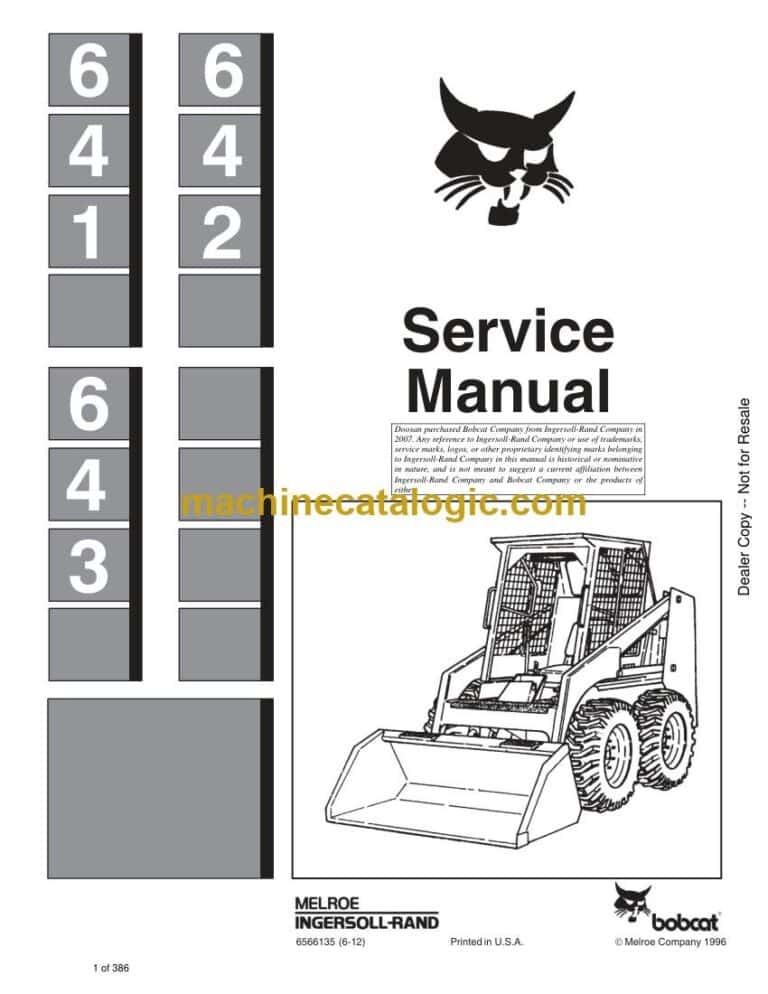
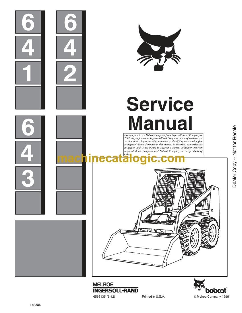
A Bobcat 642 is an older skid-steer-class loader that still earns its keep in tight jobsites, barns, and small yards. The service manual is what I keep on the bench when a machine is down and I need specs, test procedures, or a teardown sequence. Buyers usually want it when they're chasing a hydraulic issue, rebuilding a component, or trying to get an out-of-warranty loader back to work without guesswork.
What this manual helps you do
- Trace and diagnose hydraulic problems in the loader and drive circuits, using factory test ports and pressure checks
- Check and adjust engine-related systems, then verify settings after repairs or replacements
- Follow step-by-step removal and installation for pumps, drive motors, cylinders, and major mechanical assemblies
- Rebuild and reseal components like cylinders, valves, and drive units with correct disassembly and reassembly order
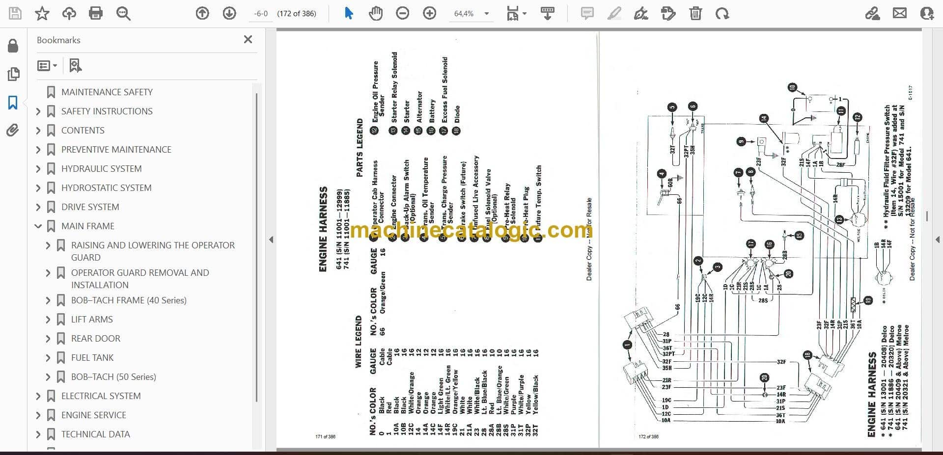
- Troubleshoot electrical issues using wiring diagrams, then verify repairs with the right test points and expected readings
Who this is for
This is for anyone maintaining or repairing a Bobcat 642 in the serial range 501411001 to 501499999: small contractors, owner-operators, shop mechanics, and rental fleets. If you just need operating tips, capacities, or daily checks, you want the operator's handbook instead, not this workshop manual.
FAQ
Q: Is this a searchable PDF, and can I zoom in on wiring diagrams?
A: These manuals are typically supplied as a PDF you can search and zoom so wiring diagrams and schematics stay readable on-screen or printed.
Q: How do I know if it covers my exact 642?
A: Check your loader's serial number plate. If it falls between 501411001 and 501499999, this is the correct service manual.
Q: Is this the right manual if I'm doing full repairs, not just maintenance?
A: Yes. This is the workshop-level service manual, meant for diagnostics, teardown, and repair, not just routine service intervals.
Bottom line: If your 642's serial number is in that range and you're doing your own repairs, this is the right manual. If your serial is outside that range, skip it.
📘 Show Index
Table of Contents:
- MAINTENANCE SAFETY
- SAFETY INSTRUCTIONS
- SAFETY IS YOUR RESPONSIBILITY
- BEFORE YOU WORK ON THE BOBCAT LOADER
- CONTENTS
- PREVENTIVE MAINTENANCE
- INTRODUCTION
- Serial Number Identification
- Loader Serial Number
- Engine Serial Number
- SERVICE SCHEDULE
- ENGINE SERVICE (General)
- Opening And Adjusting The Rear Door
- Engine Lubrication System
- Replacement Of Engine Oil And Filter
- Air Cleaner Service
- FUEL SYSTEM
- Fuel Filter (641)
- Fuel Filter (642)
- Fuel Filter (643)
- Removing Air From The Fuel System (641)
- Removing Air From The Fuel System (643)
- ENGINE COOLING SYSTEMS
- Removing Coolant From The Cooling System
- DRIVE BELTS
- ELECTRICAL SYSTEM SERVICE
- Using An Extra Battery
- Installing A New Battery
- HYDRAULIC/HYDROSTATIC SYSTEM
- HYDRAULIC/HYDROSTATIC OIL RESERVOIR
- Checking And Adding Oil
- Removing Hydraulic Oil
- Replacement Of The Hydraulic Filter
- FINAL DRIVE TRANSMISSION (CHAINCASE)
- TIRE MAINTENANCE
- LUBRICATION OF THE BOBCAT LOADER
- OPERATOR GUARD
- BOB–TACH
- PIVOT PINS
- AUXILIARY CONTROL LOCKBOLT
- LIFT ARM STOP
- SPARK ARRESTOR MUFFLER
- HYDRAULIC SYSTEM
- HYDRAULIC / HYDROSTATIC SCHEMATICS
- TROUBLESHOOTING
- HYDRAULIC SYSTEM INFORMATION
- 37° Flare Connections
- Straight Thread O–Ring Fitting
- Tubelines And Hoses
- HYDRAULIC CONTROL VALVE (Victor)
- Relief Valve
- Checking The Relief Valve
- Removal Of The Relief Valve
- Installation Of The Relief Valve
- Removal Of The Control Valve
- Disassembly Of The Control Valve (Victor)
- Assembly And Inspection Of The Control Valve
- HYDRAULIC CONTROL VALVE (Melroe)
- Relief Valve
- Installing A New Relief Valve
- Disassembling The Control Valve
- Inspecting The Control Valve
- Assembling The Control Valve
- HYDRAULIC PUMP
- Checking Output Of The Hydraulic Pump
- Removing The Hydraulic Pump
- Checking The Hydraulic Pump
- Removing And Checking The Pump Shaft
- Installing The Hydraulic Pump
- Starting Procedure For The Hydraulic Pump
- LIFT CYLINDERS
- Checking The Lift Cylinders
- Removing The Lift Cylinder
- Disassembly Of The Cylinder
- Assembly Of The Lift Cylinder
- Installation Of The Lift Cylinder(s)
- TILT CYLINDER
- Checking The Tilt Cylinder
- Removing The Tilt Cylinder
- Disassembly Of The Tilt Cylinder
- Installation Of The Tilt Cylinder
- HYDRAULIC/HYDROSTATIC RESERVOIR
- Removing The Hydraulic/Hydrostatic Reservoir
- Installing The Hydraulic/Hydrostatic Reservoir
- OIL COOLER
- Removing The Oil Cooler On The 641
- Removing The Oil Cooler From The 642 & 643
- Installing The Oil Cooler
- 10 MICRON FILTER BY–PASS VALVE
- Removing By–Pass Valve
- Installation Of The By–Pass Valve
- CONTROL PEDAL, LINKAGE AND LOCKS
- Removing Hydraulic Control Pedal
- Installing The Hydraulic Control Pedal
- Adjusting The Hydraulic Control Pedal
- Pedal Lock Linkage
- HYDROSTATIC SYSTEM
- TROUBLESHOOTING
- HYDROSTATIC SYSTEM INFORMATION
- Function Of High Pressure Relief Replenishing Valves
- STEERING LEVERS
- Removing The Steering Levers
- Repairing The Steering Levers
- Installing The Steering Levers
- STEERING LINKAGE
- Adjustment Of The Steering Linkage
- Removing The Steering Linkage
- Repairing The Pintle Lever
- Installing The Steering Linkage
- PORT BLOCK
- 40 Micron Filter
- Cold Weather By–Pass Valve
- Neutral By–Pass Valve
- Removing The Port Block
- Installing The Port Block
- HYDROSTATIC MOTOR
- Removing The Hydrostatic Motor (Model 109–1174–006 & Above)
- Removing The Hydrostatic Motor (Model 109–1052–006 & Below)
- Disassembly Of The Hydrostatic Motor
- Hydrostatic Motor Inspection
- Assembly Of The Hydrostatic Motor
- Installing The Hydrostatic Motor (Model 109–1173–006 & Above) (Splined Shaft)
- Installing the Hydrostatic Motor (Model 109–1052–006 & Below)
- Start–Up Procedure For The Hydrostatic Motor
- HYDROSTATIC PUMP
- Checking The High Pressure Relief Replenishing Valves
- Removing The Hydrostatic Pumps
- Disassembly Of The Hydrostatic Pump
- Hydrostatic Pump Inspection
- Assembly Of The Hydrostatic Pump
- Installing Pumps To Manifold Block
- Installing Hydrostatic Pump Assembly
- TOWING THE BOBCAT LOADER
- DRIVE SYSTEM
- BRAKES
- Brake Adjustment
- Brake Removal
- FINAL DRIVE
- AXLES AND BEARINGS
- Axle And Bearing Removal
- Assembly Of The Axles
- Installing The Axles
- CHAINCASE FLUID
- Replacing The Chaincase Fluid
- MAIN FRAME
- RAISING AND LOWERING THE OPERATOR GUARD
- Raising The Operator Guard
- Lowering The Operator Guard
- Jumper Start Switch
- OPERATOR GUARD REMOVAL AND INSTALLATION
- Removing The Operator Guard
- Operator Guard Installation
- BOB–TACH FRAME (40 Series)
- Removing The Bob–Tach
- Disassembly Of The Bob–Tach
- Assembly Of The Bob–Tach
- Installing The Bob–Tach
- LIFT ARMS
- Removing The Lift Arms
- Installing The Lift Arms
- REAR DOOR
- Removing The Rear Door
- Installing The Rear Door
- Adjusting The Rear Door Latch
- FUEL TANK
- Removing The Fuel Tank
- Installing The Fuel Tank
- BOB–TACH (50 Series)
- Removal And Installation
- Bob–Tach Lever And Wedge
- ELECTRICAL SYSTEM
- ELECTRICAL SCHEMATICS
- TROUBLESHOOTING
- ELECTRICAL SYSTEM INFORMATION
- Electrical Circuitry
- Safety Procedures For The Battery
- Alternator Damage
- BATTERIES
- WIRE HARNESS FOR THE OPERATOR GUARD
- Removing The Wire Harness For The Operator Guard
- Installing The Wire Harness For The Operator Guard
- WIRE HARNESS FOR THE ENGINE
- Removing The Wire Harness For The Engine
- Installing The Wire Harness For The Engine
- ALTERNATOR
- Checking The Alternator
- Removing The Alternator
- Repairing The Alternator
- Installing The Alternator
- STARTER
- Checking The Starter
- Removing The Starter
- Repairing The Starter
- ENGINE SERVICE
- ENGINE SERVICE (641 DEUTZ)
- TROUBLESHOOTING
- FUEL SYSTEM
- Fuel System Service
- Venting Air From The Fuel System
- Fuel Filters
- Fuel Water Trap
- Fuel Lift Pump
- Fuel Injection Pump
- Removal Of The Injection Pump
- Injection Pump Service
- Installing The Injection Pump
- Checking Adjustment Of Fuel Delivery
- FUEL INJECTION NOZZLES
- Removal
- Disassembly And Repair Of Injector (In The Shop)
- Installation Of The Injector
- BLOWER FAN
- Removal Of The Blower Fan
- Disassembly Of The Blower Fan
- Assembly Of The Blower Fan
- Installation Of The Blower Fan
- ENGINE SERVICE
- ENGINE REMOVAL
- CYLINDER HEAD AND VALVES
- Removal And Disassembly
- Repair And Assembly
- Checking Piston Crown Clearance And Installation Of Cylinder Head
- CYLINDER, PISTONS AND CONNECTING RODS
- OIL PUMP, FILTER HOUSING AND RELIEF VALVE
- Oil Pump Removal
- Installation
- Oil Pressure Relief Valve
- ENGINE FRONT COVER
- Removal
- Disassembly And Inspection
- Assembly
- Installation
- GOVERNOR
- Removal And Disassembly
- Assembly And Installation
- CAMSHAFT
- Removal
- Installation
- Crankshaft Removal
- Inspection
- Assembly
- UNIVERSAL JOINT
- Universal Joint Removal
- Universal Joint Installation
- FLYWHEEL
- Flywheel Removal
- Flywheel Installation
- Removing The Ring Gear
- ENGINE OIL COOLER
- ENGINE SHROUDING
- ENGINE MOUNTS
- MUFFLER
- STARTER
- ENGINE SERVICE (642 FORD)
- TROUBLESHOOTING
- CHECKS AND ADJUSTMENTS
- Oil Pressure
- Valve Clearance
- Compression
- Carburetor, Throttle And Governor Adjustments
- Ignition System
- Spark Plug Wires Resistance Test
- Spark Plug Test
- Distributor Tests
- Dwell Angle Check
- Spark Strength Tests
- Battery To Coil Voltmeter Test
- Starting Ignition Circuit Voltmeter Test
- Breaker Point Gap Adjustment
- Ignition Timing
- CARBURETOR REPAIR
- ENGINE DIAGNOSIS AND TESTING
- Camshaft Lobe Lift
- Crankshaft End Play
- Flywheel Surface Alignment Check
- Camshaft End Play
- ENGINE REMOVAL
- ENGINE REPAIR
- Valve Guides
- Grinding The Valve Seats
- Valves
- Grinding Valves
- Select Fitting Of The Valves
- Camshaft Repair
- Crankshaft
- Repairing Journals
- To Check Crankshaft Or Connection Rod Bearings With Plastigage
- Installing Pistons
- Installing Piston Rings
- Installing The Piston Pins
- Valve Rocker Arm And Shaft Assembly
- Push Rods
- CYLINDER BLOCK
- Finishing The Cylinder Walls
- CYLINDER HEADS
- Cleaning The Cylinder Heads
- Checking The Cylinder Heads
- TAPPETS
- Cleaning The Tappets
- Checking The Tappets
- CAMSHAFT
- Cleaning And Checking The Camshaft
- CRANKSHAFT
- FLYWHEEL
- CONNECTING RODS
- Cleaning The Connecting Rods
- Checking The Connecting Rods
- PISTONS, PINS AND RINGS
- Cleaning The Pistons, Pins and Rings
- Checking The Pistons, Pins And Rings
- MAIN BEARING AND CONNECTING ROD BEARINGS
- Cleaning Bearings
- Checking Bearings
- CYLINDER BLOCK
- Cleaning The Cylinder Block
- Checking The Cylinder
- OIL PUMP
- Cleaning The Oil Pump
- Checking The Oil Pump
- VALVE ROCKER ARM COVER AND ROCKER ARM SHAFT
- Removing And Disassembly Of The Rocker Arm Shaft
- Installing Rocker Arm Shaft
- VALVE PUSHRODS
- Removing The Valve Pushrods
- Installing The Valve Pushrods
- INTAKE MANIFOLD
- Removing The Intake Manifold
- Installing The Intake Manifold
- CYLINDER HEAD
- Removing The Cylinder Head
- Installing The Cylinder Head
- VALVE SPRING, RETAINER AND STEM SEAL (With The Cylinder Head Removed)
- Removing The Valve Spring
- Installing The Valve Spring
- VALVE SPRING, RETAINER AND STEM SEAL (With The Cylinder Head Installed)
- Installing The Valve Spring
- WATER PUMP
- CYLINDER FRONT COVER, TIMING CHAIN AND CRANKSHAFT SPROCKETS
- Removal
- Removing The Timing Cover
- Installation Of The Timing Cover
- FRONT OIL SEAL
- Removing The Front Oil Seal
- FRONT OIL SEAL
- Removing The Oil Seal
- Installing The Oil Seal
- TIMING CHAIN TIGHTENING
- Removing The Chain Tightener
- Installing The Chain Tightener
- CAMSHAFT AND VALVE LIFTERS
- Removing The Camshaft And Valve Lifters
- Installing The Camshaft And Valve Lifters
- OIL PAN
- Removing The Oil Pan
- Installing The Oil Pan
- OIL PUMP
- Removing The Oil Pump
- Installing The Oil Pump
- CRANKSHAFT REAR OIL SEAL
- Removing The Rear Oil Seal
- Installing The Rear Oil Seal
- MAIN BEARINGS
- Removing The Main Bearings
- Installing The Main Bearings
- CONNECTING ROD BEARINGS
- Removing The Connecting Rod Bearings
- Installing The Connecting Rod Bearings
- PISTONS AND CONNECTING RODS
- Removing The Pistons And Connecting Rods
- Installing The Pistons And Connecting Rods
- CAMSHAFT BEARINGS
- CRANKSHAFT
- Installing The Crankshaft
- UNIVERSAL JOINT
- Universal Joint Installation
- FLYWHEEL
- FLYWHEEL RING GEAR
- Removing The Ring Gear
- Installing The Ring Gear
- MUFFLER
- RADIATOR
- Removing The Radiator
- Installing The Radiator
- BLOWER HOUSING
- Removing The Blower Housing
- Installing The Blower Housing
- STARTER
- Removing The Starter
- Installing The Starter
- ENGINE SERVICE (643 KUBOTA)
- TROUBLESHOOTING
- FUEL SYSTEM
- Replacing The Fuel Filter
- To Remove The Air From The Fuel System
- Checking Glow Plugs
- Removal And Installation Of The Fuel Injection Pump
- Timing The Fuel System
- Fuel Injector Nozzles
- REMOVING AND INSTALLING THE ENGINE
- Removing The Engine
- Installing The Engine
- REPAIRING THE CYLINDER HEAD
- Removing The Cylinder Head
- Disassembly Of The Cylinder Head
- Servicing The Cylinder Head
- Assembly Of The Cylinder Head
- Installing The Cylinder Head
- Adjusting The Compression Release Mechanism (S/N 11620 and Below Only)
- REPAIRING THE ENGINE
- Removing The Gear Case
- Removing The Timing Gear, Camshaft And Oil Pump
- Removing Pistons And Crankshaft
- Servicing The Timing Gear And Camshaft
- Servicing The Connecting Rods And Pistons
- Servicing The Crankshaft
- Servicing The Cylinder Liners
- Servicing The Oil Pump
- Servicing The Water Pump
- ASSEMBLY OF THE ENGINE
- Installing The Crankshaft
- Installing Pistons
- Installing The Camshaft And Timing Gears
- Installing The Gear Case Cover
- UNIVERSAL JOINT
- Removing The U–Joint
- Installing The U–Joint
- FLYWHEEL
- Removing The Flywheel
- Installing The Flywheel
- MUFFLER
- RADIATOR
- Removing The Radiator
- Installing The Radiator
- BLOWER HOUSING
- Removing The Blower Housing
- Installing The Blower Housing
- STARTER
- Removing The Starter
- Installing The Starter
- TECHNICAL DATA
- TECHNICAL DATA (641 DEUTZ)
- 641 LOADER SPECIFICATIONS
- OPERATION & PERFORMANCE SPECIFICATIONS
- ENGINE SPECIFICATIONS
- HYDRAULIC SYSTEM
- HYDRAULIC CYLINDERS
- HYDROSTATIC TRANSMISSION & FINAL DRIVE
- ELECTRICAL
- TIRES
- FLUID CAPACITIES
- ENGINE SPECIFICATIONS, 641 (Deutz – F2L511)
- Fuel System
- Governor, Front Cover And Throttle
- Cylinder Head And Valves
- Cylinder, Piston And Connecting Rod
- Camshaft, Crankshaft, Bearings
- Lubrication System
- Torque Specifications (Deutz Engine)
- TECHNICAL DATA (642 FORD)
- 642 LOADER SPECIFICATIONS
- OPERATION & PERFORMANCE
- ENGINE SPECIFICATIONS
- HYDRAULIC SYSTEM
- HYDRAULIC CYLINDERS
- HYDROSTATIC TRANSMISSION & FINAL DRIVE
- ELECTRICAL
- TIRES
- FLUID CAPACITIES
- ENGINE SPECIFICATIONS, 642 (Ford)
- Fuel Specifications
- Engine Oil
- Lubrication System
- Cylinder Heads
- Valve Mechanism
- Camshaft
- Crankshaft
- Connecting Rod
- Piston
- Piston Pin
- Piston Rings
- Cylinder Block
- Ignition system
- Starter
- Torque Specifications For Engine
- TECHNICAL DATA (643 KUBOTA)
- 643 LOADER SPECIFICATIONS
- OPERATION & PERFORMANCE
- ENGINE SPECIFICATIONS
- HYDRAULIC SYSTEM
- HYDROSTATIC TRANSMISSION & FINAL DRIVE
- ELECTRICAL
- TIRES
- FLUID CAPACITIES
- ENGINE SPECIFICATIONS
- Fuel Injection Nozzles
- Fuel Injection Pump
- Cylinder Head
- Valves
- Valve Springs
- Rocker Arms
- Camshaft
- Cylinder
- Piston Rings
- Pistons
- Crankshaft
- Oil Pump
- Engine Oil
- ENGINE BOLT TORQUES
- TECHNICAL DATA
- TORQUE SPECIFICATIONS
- Engine Group (641)
- Engine Group (642)
- Engine Group (643)
- Mainframe Group (All 640 Series)
- Seat Bar, Fuel Tank & Panel Group
- Steering Levers, Linkage Pedal Group (640 Series)
- Brake, Axle And Chaincase Group (640 Series)
- Hydraulic/Hydrostatic Group (640 Series)
- HYDRAULIC/HYDROSTATIC FLUID SPECIFICATIONS
- Hydraulic/Hydrostatic Fluid
- DECIMAL AND MILLIMETER EQUIVALENTS
- U.S. TO METRIC CONVERSION
- STANDARD TORQUE SPECIFICATIONS FOR BOLTS
- SERVICE BULLETINS
- SERVICE MANUAL REVISIONS
- 640-3
- 640-4
- 640–5
- 640–6
- 640–7
- 640–8
- 640–9
- 640–10
- 640–11
- 640–12
- 640–13
- 640–14
- 640–15
- 640–16
- 640–17
- 640–18
- 640–19
- 640–20
- 640-21
Bobcat Software
Bobcat PDF Manuals