The Bobcat 331 is a small excavator you'll see trenching, setting lines, digging footings, and doing farm or landscape work. People grab the service manual when the machine is out of warranty and they're chasing a hydraulic issue, an electrical fault, or doing real teardown work. Around my shop, this is what you pull when you need specs and step-by-step, not "how to run the controls."
What this manual helps you do
- Diagnose hydraulic problems, check pressures, and trace leaks in the 331's excavator-class hydraulic system
- Follow teardown and reassembly steps for components like cylinders, swing motor, and final drives
- Troubleshoot electrical issues using wiring diagrams, connector callouts, and test procedures
- Set and verify adjustments for controls, linkages, track tension, and machine settings
- Replace major assemblies and verify you're putting hoses, lines, and wiring back where Bobcat intended
Who this is for
This manual is for anyone working on a Bobcat 331 excavator with serial number A9K511001 through A9K599999: small contractors, owner-operators, rental fleets, and shop or field mechanics. If you only want operating tips or daily maintenance charts, you want the operator's handbook instead, not this service manual.
FAQ
Q: Is this a searchable PDF and are the wiring diagrams readable?
A: Yes, it's a PDF, and you can search text. Wiring diagrams are scan-based but laid out so you can zoom in and still read them on a screen.
Q: Will this cover my exact 331?
A: Check your serial number plate. If it falls between A9K511001 and A9K599999, this is the right manual. If it doesn't, you need a different book.
Q: Is this the right document if I'm doing full repairs?
A: Yes. This is the workshop-level service manual, not a parts list and not an operator's book.
Bottom line: If your 331's serial number is in that A9K511001-A9K599999 range and you're doing real repair work, this is the manual you want.
📘 Show Index
Table of Contents:
- MAINTENANCE SAFETY
- CONTENTS
- FOREWORD
- FOREWORD
- SAFETY INSTRUCTIONS
- FIRE PREVENTION
- Maintenance
- Operation
- Electrical
- Hydraulic System
- Fueling
- Starting
- Spark Arrester Exhaust System
- Welding And Grinding
- Fire Extinguishers
- SERIAL NUMBER LOCATIONS
- Excavator Serial Number
- Engine Serial Number
- DELIVERY REPORT
- EXCAVATOR IDENTIFICATION
- SAFETY AND MAINTENANCE
- LIFTING AND BLOCKING THE EXCAVATOR
- UPPERSTRUCTURE SLEW LOCK
- LIFTING THE EXCAVATOR
- OPERATOR CAB (ROPS / TOPS)
- Description
- Cab Door
- Front Window
- Front Wiper
- Window Washer Reservoir
- Right Side Windows
- Heating, Ventilation, and Air Conditioning Duct
- TRANSPORTING THE EXCAVATOR ON A TRAILER
- Loading And Unloading
- Fastening
- TAILGATE
- Opening And Closing
- Adjusting The Bumper
- Adjusting The Latch
- RIGHT SIDE COVER
- Opening And Closing
- Adjusting The Latch
- SERVICE SCHEDULE
- AIR CLEANER SERVICE
- Daily Check
- Replacing The Filter Elements
- ENGINE COOLING SYSTEM
- Cleaning
- Checking Level
- Replacing The Coolant
- FUEL SYSTEM
- Fuel Specifications
- Biodiesel Blend Fuel
- Filling The Fuel Tank
- Fuel Filters
- Draining The Fuel Tank
- Removing Air From The Fuel System
- ENGINE LUBRICATION SYSTEM
- Checking And Adding Engine Oil
- Oil Chart
- Removing And Replacing Oil And Filter
- HYDRAULIC SYSTEM
- Checking And Adding Hydraulic Oil
- Hydraulic Fluid Chart
- Removing And Replacing The Hydraulic Filter
- Replacing The Case Drain Filter
- Removing And Replacing The Hydraulic Fluid
- LUBRICATION OF THE HYDRAULIC EXCAVATOR
- TRAVEL MOTOR
- Checking And Adding Oil
- Removing And Replacing Oil
- SPARK ARRESTER MUFFLER
- ENGINE ACCESSORY DRIVE BELT
- SEAT BELT
- Inspection And Maintenance
- PIVOT PINS
- Inspection And Maintenance
- EXCAVATOR STORAGE AND RETURN TO SERVICE
- Storage
- Return to Service
- STOPPING THE ENGINE AND LEAVING THE EXCAVATOR
- Procedure
- Emergency Exits
- REMOTE START TOOL KIT – MEL1563
- Remote Start Tool Kit – MEL1563
- Service Tool Harness Control – MEL1565
- Service Tool Harness Communicator – MEL1566
- REMOTE START TOOL (SERVICE TOOL) KIT – 7003031
- Description
- Remote Start Tool (Service Tool) – 7003030
- Excavator Service Tool Harness – 6689747
- Computer Service Tool Harness – 6689746
- HYDRAULIC SYSTEM
- HYDRAULIC/HYDROSTATIC SCHEMATICS
- HYDRAULIC SYSTEM INFORMATION
- Glossary Of Hydraulic / Hydrostatic Symbols For Excavators
- Troubleshooting The Hydraulic Circuit
- Troubleshooting The Cylinder Circuit
- Troubleshooting The Swing (Upperstructure Slew) Circuit
- Troubleshooting The Travel Circuit
- CYLINDER (BOOM)
- Testing
- Removal And Installation
- Parts Identification
- Disassembly
- Assembly
- CYLINDER (ARM)
- Testing
- Removal And Installation
- Parts Identification
- Disassembly
- Assembly
- CYLINDER (BOOM SWING)
- Testing
- Removal And Installation
- Parts Identification
- Disassembly
- Assembly
- CYLINDER (BUCKET)
- Testing
- Removal And Installation (Standard And Long Arm)
- Removal And Installation (Extendable Arm)
- Parts Identification
- Disassembly
- Assembly
- CYLINDER (BLADE)
- Testing
- Removal And Installation
- Parts Identification
- Disassembly
- Assembly
- CYLINDER (EXTENDABLE ARM)
- Removal And Installation
- Parts Identification
- Disassembly
- Assembly
- CYLINDER (CLAMP)
- Testing
- Removal And Installation
- Parts Identification
- Disassembly
- Assembly
- VALVE (MAIN RELIEF)
- Testing And Adjusting The Main Relief Valve
- VALVES (PORT RELIEF)
- Testing And Adjusting Port Relief Valve Pressure
- VALVES (CROSSPORT RELIEF)
- Testing And Adjusting The Crossport Relief Valves
- VALVE (PRESSURE REDUCING)
- Testing And Adjusting The Pressure Reducing Valve
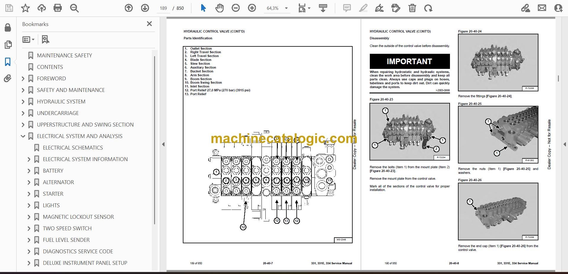
- HYDRAULIC CONTROL VALVE
- Description
- Removal And Installation
- Parts Identification
- Disassembly
- Right Travel Valve Section Disassembly And Assembly
- Left Travel Valve Section Disassembly And Assembly
- Blade Valve Section Disassembly And Assembly
- Slew Valve Section Disassembly And Assembly
- Auxiliary Valve Section Disassembly And Assembly
- Bucket Valve Section Disassembly And Assembly
- Arm Valve Section Disassembly And Assembly
- Boom Valve Section Disassembly And Assembly
- Boom Swing Valve Section Disassembly And Assembly
- Inlet Section Disassembly And Assembly
- Assembly
- HYDRAULIC PUMP
- Description
- Torque Adjustment
- Testing The Piston Pump
- Testing Auxiliary Hydraulic Flow
- Removal And Installation
- Coupler Removal And Installation
- Hydraulic Pump Start Up
- Parts Identification
- Disassembly
- Assembly
- MANIFOLD ASSEMBLY / ACCUMULATOR
- Description
- Removal And Installation
- Parts Identification
- Disassembly And Assembly
- TRAVEL MOTOR
- Removal And Installation
- Parts Identification
- Disassembly
- Assembly
- SWIVEL JOINT
- Description
- Removal And Installation
- Parts Identification
- Disassembly
- Assembly
- SWING MOTOR
- Removal And Installation
- Parts Identification
- Disassembly
- Assembly
- SWING MOTOR DRIVE CARRIER
- Removal And Installation
- Parts Identification
- Disassembly
- Assembly
- CONTROL PATTERN SELECTOR VALVE
- Removal And Installation
- Parts Identification
- Disassembly
- Assembly
- RIGHT CONTROL LEVER (JOYSTICK)
- Testing
- Handle Removal And Installation
- Joystick Assembly Removal And Installation
- Parts Identification
- Disassembly
- Assembly
- LEFT CONTROL LEVER (JOYSTICK)
- Testing
- Handle Removal And Installation
- Joystick Assembly Removal And Installation
- Parts Identification
- Disassembly
- Assembly
- HYDRAULIC FILTER MOUNT
- HYDRAULIC RESERVOIR
- OIL COOLER
- DIRECT TO TANK VALVE
- Removal And Installation
- Parts Identification
- Disassembly And Assembly
- CASE DRAIN FILTER
- BOOM SWING LOCK VALVE
- Removal And Installation
- Parts Identification
- Disassembly
- Assembly
- TRAVEL CONTROL VALVE
- Removal and Installation
- Parts Identification
- Disassembly And Assembly
- HYDRAULIC X-CHANGE™ VALVE
- Removal And Installation
- Parts Identification
- Disassembly
- Assembly
- SLEW LOCK VALVE
- Description
- Removal And Installation
- Parts Identification
- Disassembly And Assembly
- UNDERCARRIAGE
- BLADE
- TRACKS
- Track Lug Height
- Adjustment
- Rubber Track Removal And Installation
- Steel Track Removal And Installation
- TRACK FRAME
- Disassembly And Assembly
- Recoil Spring Cylinder (S/N AACS11750 & Below, A9K511103 & Below, A9K711102 & Below And A9K911051 & Below)
- Recoil Spring Cylinder Parts Identification (With Replaceable Shaft) (S/N AACS11751 & Above, A9K511104 & Above, A9K711103 & Above And A9K91102 & Above)
- Recoil Spring Cylinder (With Replaceable Shaft) (S/N AACS11751 & Above, A9K511104 & Above, A9K711103 & Above And A9K911052 & Above)
- TRACK DAMAGE IDENTIFICATION
- Cutting Of Steel Cords
- Abrasion Of Embedded Metals
- Separation Of Embedded Metals
- Separation Of Embedded Metals Due To Corrosion
- Cuts On The Lug Side Rubber
- Cracks On The Lug Side Rubber Due To Fatigue
- Lug Abrasion
- Cracks And Cuts On The Lug Side Rubber
- Abrasion Of The Track Roller Side
- Cuts On The Edges Of Track Roller Side
- TRACK IDLER
- Parts Identification
- Disassembly
- Assembly
- TRACK ROLLER
- Parts Identification
- Disassembly
- Assembly
- SWING CIRCLE GEAR
- Swing Bearing Removal
- Swing Bearing Installation
- UPPERSTRUCTURE AND SWING SECTION
- UPPERSTRUCTURE
- ROPS CANOPY
- CAB
- Removal And Installation
- Door Removal And Installation
- Front Window Removal And Installation
- Right Side Rear Sliding Window Removal And Installation
- Right Side Front Sliding Window Removal And Installation
- Right Side Front And Rear Sliding Window Weather Strip Removal And Installation
- Right Side Front And Rear Sliding Window Wiper Strip Removal And Installation
- Glass Removal
- Glass Installation
- SEAT AND SEAT MOUNT
- RIGHT CONSOLE
- Console Cover Removal And Installation
- Console Base Removal And Installation
- LEFT CONSOLE
- Lower Console Cover Removal And Installation
- Upper Console Cover Removal And Installation
- Compression Spring Removal And Installation
- Compression Spring Disassembly And Assembly
- Lock Lever Removal And Installation
- Console Removal And Installation
- Disassembly And Assembly
- Console Base Removal And Installation
- ENGINE SPEED CONTROL
- Removal And Installation
- Adjustment (Later Models)
- BLADE CONTROL
- Lever Removal And Installation
- Linkage Removal And Installation
- Linkage Bar Removal And Installation
- Lower Linkage Removal And Installation
- RIGHT PEDAL AND LINKAGE
- Pedal Removal And Installation
- Pedal Disassembly And Assembly
- Linkage Removal And Installation
- TRAVEL CONTROLS
- Removal And Installation
- Disassembly And Assembly
- Adjustment
- Control Linkage Removal And Installation
- FLOOR MAT AND FLOOR PANEL
- Removal And Installation (Canopy Equipped Excavators)
- Removal And Installation (Cab Equipped Excavators)
- FUEL TANK
- HORN
- SWING FRAME
- Removal And Installation
- Boom Swing Frame Hose Routing
- Bushing Removal
- Bushing Installation
- BOOM
- STANDARD AND LONG ARM
- Removal And Installation
- Arm To Boom Bushing Removal And Installation
- Arm To Bucket And Bucket Link Bushing Removal And Installation
- Arm To Bucket And Bucket Link Bushing Removal And Installation (Cont’d)
- EXTENDABLE ARM
- Removal And Installation
- Disassembly And Assembly
- BUCKET
- Bucket Teeth Removal And Installation
- Bucket Side Cutting Edge Removal And Installation
- CLAMP
- TAILGATE
- Removal And Installation
- Latch Removal And Installation
- X-CHANGE™
- Removal And Installation
- Disassembly
- Assembly
- Check Proper Latch Engagement
- X-CHANGE™ (HYDRAULIC)
- Removal And Installation
- Parts Identification
- Disassembly
- Assembly
- UPPERSTRUCTURE SLEW LOCK
- Removal And Installation
- Disassembly And Assembly
- RIGHT SIDE COVER
- QUICK COUPLER (KLAC™ SYSTEM)
- Troubleshooting
- Daily Inspection
- Removal And Installation
- Parts Identification
- Disassembly
- Assembly
- QUICK COUPLER (LEHNHOFF® SYSTEM)
- Troubleshooting
- Daily Inspection
- Removal (MS03 And MS08)
- Installation (MS03 And MS08)
- Parts Identification (MS03)
- Disassembly And Assembly (MS03)
- Parts Identification (MS08)
- Disassembly (MS08)
- Assembly (MS08)
- ELECTRICAL SYSTEM AND ANALYSIS
- ELECTRICAL SCHEMATICS
- ELECTRICAL SYSTEM INFORMATION
- Troubleshooting Chart
- Description
- Fuse And Relay Location
- BATTERY
- Servicing
- Removal And Installation
- Using A Booster Battery (Jump Starting)
- ALTERNATOR
- Engine Accessory Drive Belt
- Removal And Installation
- Alternator Identification
- Charging System Check
- Alternator Voltage Test
- Low Voltage Test
- High Voltage Test
- Rectifier Continuity (Diode) Test
- Alternator Regulator Test
- Parts Identification
- Disassembly
- Stator Continuity Test
- Stator Ground Test
- Rotor Continuity Test
- Rotor Ground Test
- Assembly
- STARTER
- Removal And Installation
- Parts Identification
- Disassembly
- Inspection And Repair
- Assembly
- LIGHTS
- Removal And Installation
- Boom Light Removal And Installation
- Boom Light Bulb Replacement
- MAGNETIC LOCKOUT SENSOR
- TWO SPEED SWITCH
- FUEL LEVEL SENDER
- Removal And Installation
- Testing
- DIAGNOSTICS SERVICE CODE
- DELUXE INSTRUMENT PANEL SETUP
- Passwords
- Password Entry (For Starting and Operating the Machine)
- Changing The Owner Or Operator Password
- Password Lockout Feature
- Job Clock
- RPM
- ENGINE SERVICE
- TROUBLESHOOTING
- SPARK ARRESTER MUFFLER
- AIR CLEANER
- RADIATOR
- ENGINE COMPONENTS AND TESTING
- Engine Compression Checking
- Glow Plugs Removal And Installation
- Checking The Glow Plug
- Fuel Shut-off Solenoid Removal And Installation
- Fuel Injection Pump Check
- Fuel Injection Pump Removal And Installation
- Fuel Injection Pump Timing
- Fuel Injector Nozzles Removal And Installation
- Fuel Injector Nozzle Check
- Valve Clearance Adjustment
- ENGINE
- ENGINE FLYWHEEL
- Hydraulic Pump Coupler Removal And Installation
- Flywheel Removal And Installation
- Flywheel Ring Gear
- RECONDITIONING THE ENGINE
- Cylinder Head Removal And Installation
- Cylinder Head Disassembly And Assembly
- Cylinder Head Servicing
- Cylinder Head Top Clearance
- Valve Guide Checking
- Reconditioning The Valve And Valve Seat
- Valve Spring
- Rocker Arm And Shaft Checking
- Timing Gearcase Cover Removal And Installation
- Idler Gear And Camshaft Removal And Installation
- Camshaft Servicing
- Idler Gear And Shaft Servicing
- Timing Gears Checking Backlash
- Fuel Camshaft Removal And Installation
- Fuel Camshaft Governor
- Crankshaft Gear Removal And Installation
- Oil Pump Removal And Installation
- Oil Pump Service
- Checking Engine Oil Pressure
- Valve Tappets
- Piston And Connecting Rod Removal And Installation
- Piston And Connecting Rod Servicing
- Connecting Rod Alignment
- Crankshaft And Bearings Removal And Installation
- Crankshaft And Bearings Servicing
- Cylinder Bore Checking
- Water Pump Removal And Installation
- Water Pump Disassembly And Assembly
- Fan Removal And Installation
- HEATING, VENTILATION AND AIR CONDITIONING (HVAC)
- HEATER COIL
- Removal And Installation With A/C
- Removal And Installation Without A/C
- BLOWER FAN
- Removal And Installation
- Disassembly And Assembly
- Resistor Removal And Installation
- HEATER VALVE
- AIR CONDITIONING SYSTEM FLOW
- COMPONENTS
- SAFETY
- REGULAR MAINTENANCE
- Heater Air Filter
- Engine Accessory Drive Belt Inspection
- Cleaning The Condenser
- BASIC TROUBLESHOOTING
- Poor A/C Performance
- Cleaning The A/C Evaporator Coil And Heater Coil
- Engine Accessory Drive Belt Inspection
- Checking The Electrical System
- Engine Coolant By-Passing The Heater Valve
- GENERAL AIR CONDITIONING SERVICE GUIDELINES
- Compressor Oil
- Compressor Oil Check
- Component Replacement And Refrigeration Leaks
- SYSTEM TROUBLESHOOTING CHART
- Blower Motor Does Not Operate
- Blower Motor Operates Normally, But Air Flow Is Insufficient
- Insufficient Cooling Although Air Flow And Compressor Operation Are Normal
- The Compressor Operates Improperly Or Not At All
- Gauge Pressure Related Troubleshooting
- TEMPERATURE / PRESSURE
- AIR CONDITIONING SERVICE
- SYSTEM CHARGING AND RECLAMATION
- Reclamation Procedure
- Charging Procedure With A Manifold Gauge Set
- COMPRESSOR
- Removal And Installation
- Compressor Clutch Disassembly And Assembly
- CONDENSER
- RECEIVER / DRIER
- PRESSURE RELIEF VALVE
- PRESSURE SWITCH
- EVAPORATOR / HEATER UNIT
- Removal And Installation
- Disassembly And Assembly
- THERMOSTAT
- EXPANSION VALVE
- EVAPORATOR
- SPECIFICATIONS
- SPECIFICATIONS
- 331, 331E With Long Arm Option And 334 Excavator Machine Dimensions
- 331 With Extendable Arm Option And 331E Excavator Machine Dimensions
- Performance
- Controls
- Engine
- Hydraulic System
- Hydraulic Cylinders
- Hydraulic Cycle Times
- Drive System
- Undercarriage
- Track
- Ground Pressure
- Electrical
- ENGINE SPECIFICATIONS
- Fuel Injection Nozzles
- Fuel Injection Pump
- Cylinder Head
- Valves
- Valve Springs
- Valve Timing
- Rocker Arms
- Camshaft
- Tappet
- Cylinders
- Piston Rings
- Pistons
- Connecting Rods
- Oil Pump
- Crankshaft
- Timing Gear
- Thermostat
- Engine Bolt Torque
- Crankshaft Re-Grind Data
- TORQUE SPECIFICATIONS
- Torque For General SAE Bolts
- Torque For General Metric Bolts
- HYDRAULIC CONNECTION SPECIFICATIONS
- O-Ring Face Seal Connection
- Straight Thread O-Ring Fitting
- Tubelines And Hoses
- Flare Fitting
- O-Ring Flare Fitting
- Port Seal Fitting
- HYDRAULIC FLUID SPECIFICATIONS
- SERVICE TOOLS REQUIRED
- Remote Start Tools
- Hydraulic Tools
- Engine Tools
- HVAC Tools
- CONVERSIONS
- Decimal And Millimeter Equivalents
- U.S. To Metric Conversion
- ALPHABETICAL INDEX
Bobcat Software
Bobcat PDF Manuals


