A Bobcat 331 is a compact excavator you'll see trenching, setting small structures, digging footings, and cleaning up around houses and barns. The person who reaches for this service manual is the one actually turning wrenches, chasing electrical gremlins, or trying to get hydraulic pressures back where they belong. They're past the "how do I run it" stage and into "how do I fix what's broken and not guess."
What this manual helps you do
- Diagnose hydraulic problems, check test ports, and compare readings to the specs Bobcat calls for on the 331 in this serial range.
- Trace and troubleshoot wiring and sensor issues using the 331-specific electrical diagrams and harness layouts.
- Follow teardown and reassembly steps for the engine, pumps, drive motors, and swing components on this exact model.
- Replace and adjust cylinders, valves, and linkages with the right sequences and adjustment procedures.
- Verify fluid types, service intervals, and inspection points for the 331 so you're not mixing info from other models.
Who this is for
If you own or work on a Bobcat 331 with a serial number between AACS11001 and AACS99999, this is the right service manual. It suits small contractors, owner-operators, rental fleets, and shop or field mechanics who are doing real repair work. If you just need basic controls, safety, and daily checks, you want the operator's handbook instead.
FAQ
Q: Is this a searchable PDF, and can I read the wiring diagrams clearly?
A: These manuals are usually supplied as searchable PDFs, and the wiring diagrams are meant to be zoomed in on a screen or printed.
Q: How do I know it matches my exact 331?
A: Check your machine's serial tag. If it falls between AACS11001 and AACS99999, this is the correct book.
Q: Is this the right document for basic maintenance only?
A: It covers maintenance, but it's really aimed at repair and diagnostics. For simple greasing and daily checks, the operator's manual is easier.
If your 331's serial number is in that AACS11001-AACS99999 window and you're doing your own repairs, this is the manual you want. If the serial does not match, skip it.
📘 Show Index
Table of Contents:
- MAINTENANCE SAFETY
- CONTENTS
- FOREWORD
- FOREWORD
- SAFETY INSTRUCTIONS
- FIRE PREVENTION
- Maintenance
- Operation
- Electrical
- Hydraulic System
- Fueling
- Starting
- Spark Arrester Exhaust System
- Welding And Grinding
- Fire Extinguishers
- SERIAL NUMBER LOCATIONS
- Excavator Serial Number
- Engine Serial Number
- DELIVERY REPORT
- EXCAVATOR IDENTIFICATION
- SAFETY AND MAINTENANCE
- LIFTING AND BLOCKING THE EXCAVATOR
- UPPERSTRUCTURE SLEW LOCK
- LIFTING THE EXCAVATOR
- OPERATOR CAB (ROPS / TOPS)
- Description
- Cab Door
- Front Window
- Front Wiper
- Window Washer Reservoir
- Right Side Windows
- Heating, Ventilation, and Air Conditioning Duct
- TRANSPORTING THE EXCAVATOR ON A TRAILER
- Loading And Unloading
- Fastening
- TAILGATE
- Opening And Closing
- Adjusting The Bumper
- Adjusting The Latch
- RIGHT SIDE COVER
- Opening And Closing
- Adjusting The Latch
- SERVICE SCHEDULE
- AIR CLEANER SERVICE
- Daily Check
- Replacing The Filter Elements
- ENGINE COOLING SYSTEM
- Cleaning
- Checking Level
- Replacing The Coolant
- FUEL SYSTEM
- Fuel Specifications
- Biodiesel Blend Fuel
- Filling The Fuel Tank
- Fuel Filters
- Draining The Fuel Tank
- Removing Air From The Fuel System
- ENGINE LUBRICATION SYSTEM
- Checking And Adding Engine Oil
- Oil Chart
- Removing And Replacing Oil And Filter
- HYDRAULIC SYSTEM
- Checking And Adding Hydraulic Oil
- Hydraulic Fluid Chart
- Removing And Replacing The Hydraulic Filter
- Replacing The Case Drain Filter
- Removing And Replacing The Hydraulic Fluid
- LUBRICATION OF THE HYDRAULIC EXCAVATOR
- TRAVEL MOTOR
- Checking And Adding Oil
- Removing And Replacing Oil
- SPARK ARRESTER MUFFLER
- ENGINE ACCESSORY DRIVE BELT
- SEAT BELT
- Inspection And Maintenance
- PIVOT PINS
- Inspection And Maintenance
- EXCAVATOR STORAGE AND RETURN TO SERVICE
- Storage
- Return to Service
- STOPPING THE ENGINE AND LEAVING THE EXCAVATOR
- Procedure
- Emergency Exits
- REMOTE START TOOL KIT – MEL1563
- Remote Start Tool Kit – MEL1563
- Service Tool Harness Control – MEL1565
- Service Tool Harness Communicator – MEL1566
- REMOTE START TOOL (SERVICE TOOL) KIT – 7003031
- Description
- Remote Start Tool (Service Tool) – 7003030
- Excavator Service Tool Harness – 6689747
- Computer Service Tool Harness – 6689746
- HYDRAULIC SYSTEM
- HYDRAULIC/HYDROSTATIC SCHEMATICS
- HYDRAULIC SYSTEM INFORMATION
- Glossary Of Hydraulic / Hydrostatic Symbols For Excavators
- Troubleshooting The Hydraulic Circuit
- Troubleshooting The Cylinder Circuit
- Troubleshooting The Swing (Upperstructure Slew) Circuit
- Troubleshooting The Travel Circuit
- CYLINDER (BOOM)
- Testing
- Removal And Installation
- Parts Identification
- Disassembly
- Assembly
- CYLINDER (ARM)
- Testing
- Removal And Installation
- Parts Identification
- Disassembly
- Assembly
- CYLINDER (BOOM SWING)
- Testing
- Removal And Installation
- Parts Identification
- Disassembly
- Assembly
- CYLINDER (BUCKET)
- Testing
- Removal And Installation (Standard And Long Arm)
- Removal And Installation (Extendable Arm)
- Parts Identification
- Disassembly
- Assembly
- CYLINDER (BLADE)
- Testing
- Removal And Installation
- Parts Identification
- Disassembly
- Assembly
- CYLINDER (EXTENDABLE ARM)
- Removal And Installation
- Parts Identification
- Disassembly
- Assembly
- CYLINDER (CLAMP)
- Testing
- Removal And Installation
- Parts Identification
- Disassembly
- Assembly
- VALVE (MAIN RELIEF)
- Testing And Adjusting The Main Relief Valve
- VALVES (PORT RELIEF)
- Testing And Adjusting Port Relief Valve Pressure
- VALVES (CROSSPORT RELIEF)
- Testing And Adjusting The Crossport Relief Valves
- VALVE (PRESSURE REDUCING)
- Testing And Adjusting The Pressure Reducing Valve
- HYDRAULIC CONTROL VALVE
- Description
- Removal And Installation
- Parts Identification
- Disassembly
- Right Travel Valve Section Disassembly And Assembly
- Left Travel Valve Section Disassembly And Assembly
- Blade Valve Section Disassembly And Assembly
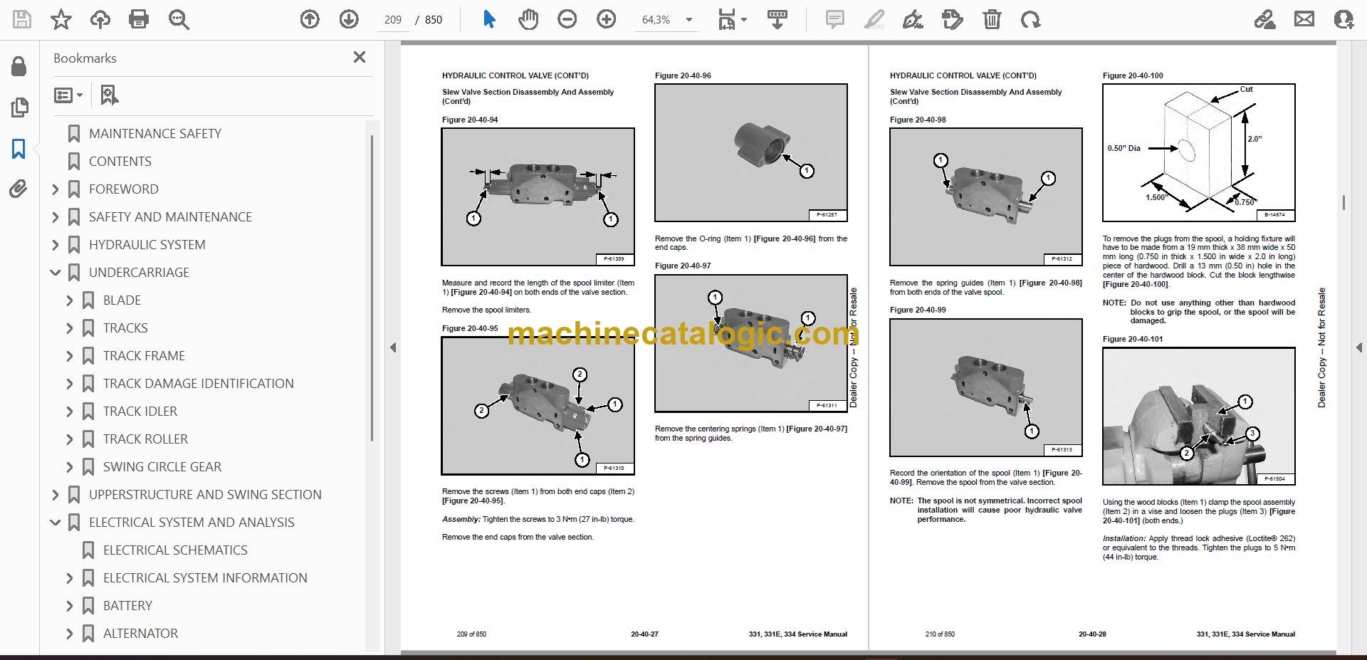
- Slew Valve Section Disassembly And Assembly
- Auxiliary Valve Section Disassembly And Assembly
- Bucket Valve Section Disassembly And Assembly
- Arm Valve Section Disassembly And Assembly
- Boom Valve Section Disassembly And Assembly
- Boom Swing Valve Section Disassembly And Assembly
- Inlet Section Disassembly And Assembly
- Assembly
- HYDRAULIC PUMP
- Description
- Torque Adjustment
- Testing The Piston Pump
- Testing Auxiliary Hydraulic Flow
- Removal And Installation
- Coupler Removal And Installation
- Hydraulic Pump Start Up
- Parts Identification
- Disassembly
- Assembly
- MANIFOLD ASSEMBLY / ACCUMULATOR
- Description
- Removal And Installation
- Parts Identification
- Disassembly And Assembly
- TRAVEL MOTOR
- Removal And Installation
- Parts Identification
- Disassembly
- Assembly
- SWIVEL JOINT
- Description
- Removal And Installation
- Parts Identification
- Disassembly
- Assembly
- SWING MOTOR
- Removal And Installation
- Parts Identification
- Disassembly
- Assembly
- SWING MOTOR DRIVE CARRIER
- Removal And Installation
- Parts Identification
- Disassembly
- Assembly
- CONTROL PATTERN SELECTOR VALVE
- Removal And Installation
- Parts Identification
- Disassembly
- Assembly
- RIGHT CONTROL LEVER (JOYSTICK)
- Testing
- Handle Removal And Installation
- Joystick Assembly Removal And Installation
- Parts Identification
- Disassembly
- Assembly
- LEFT CONTROL LEVER (JOYSTICK)
- Testing
- Handle Removal And Installation
- Joystick Assembly Removal And Installation
- Parts Identification
- Disassembly
- Assembly
- HYDRAULIC FILTER MOUNT
- HYDRAULIC RESERVOIR
- OIL COOLER
- DIRECT TO TANK VALVE
- Removal And Installation
- Parts Identification
- Disassembly And Assembly
- CASE DRAIN FILTER
- BOOM SWING LOCK VALVE
- Removal And Installation
- Parts Identification
- Disassembly
- Assembly
- TRAVEL CONTROL VALVE
- Removal and Installation
- Parts Identification
- Disassembly And Assembly
- HYDRAULIC X-CHANGE™ VALVE
- Removal And Installation
- Parts Identification
- Disassembly
- Assembly
- SLEW LOCK VALVE
- Description
- Removal And Installation
- Parts Identification
- Disassembly And Assembly
- UNDERCARRIAGE
- BLADE
- TRACKS
- Track Lug Height
- Adjustment
- Rubber Track Removal And Installation
- Steel Track Removal And Installation
- TRACK FRAME
- Disassembly And Assembly
- Recoil Spring Cylinder (S/N AACS11750 & Below, A9K511103 & Below, A9K711102 & Below And A9K911051 & Below)
- Recoil Spring Cylinder Parts Identification (With Replaceable Shaft) (S/N AACS11751 & Above, A9K511104 & Above, A9K711103 & Above And A9K91102 & Above)
- Recoil Spring Cylinder (With Replaceable Shaft) (S/N AACS11751 & Above, A9K511104 & Above, A9K711103 & Above And A9K911052 & Above)
- TRACK DAMAGE IDENTIFICATION
- Cutting Of Steel Cords
- Abrasion Of Embedded Metals
- Separation Of Embedded Metals
- Separation Of Embedded Metals Due To Corrosion
- Cuts On The Lug Side Rubber
- Cracks On The Lug Side Rubber Due To Fatigue
- Lug Abrasion
- Cracks And Cuts On The Lug Side Rubber
- Abrasion Of The Track Roller Side
- Cuts On The Edges Of Track Roller Side
- TRACK IDLER
- Parts Identification
- Disassembly
- Assembly
- TRACK ROLLER
- Parts Identification
- Disassembly
- Assembly
- SWING CIRCLE GEAR
- Swing Bearing Removal
- Swing Bearing Installation
- UPPERSTRUCTURE AND SWING SECTION
- UPPERSTRUCTURE
- ROPS CANOPY
- CAB
- Removal And Installation
- Door Removal And Installation
- Front Window Removal And Installation
- Right Side Rear Sliding Window Removal And Installation
- Right Side Front Sliding Window Removal And Installation
- Right Side Front And Rear Sliding Window Weather Strip Removal And Installation
- Right Side Front And Rear Sliding Window Wiper Strip Removal And Installation
- Glass Removal
- Glass Installation
- SEAT AND SEAT MOUNT
- RIGHT CONSOLE
- Console Cover Removal And Installation
- Console Base Removal And Installation
- LEFT CONSOLE
- Lower Console Cover Removal And Installation
- Upper Console Cover Removal And Installation
- Compression Spring Removal And Installation
- Compression Spring Disassembly And Assembly
- Lock Lever Removal And Installation
- Console Removal And Installation
- Disassembly And Assembly
- Console Base Removal And Installation
- ENGINE SPEED CONTROL
- Removal And Installation
- Adjustment (Later Models)
- BLADE CONTROL
- Lever Removal And Installation
- Linkage Removal And Installation
- Linkage Bar Removal And Installation
- Lower Linkage Removal And Installation
- RIGHT PEDAL AND LINKAGE
- Pedal Removal And Installation
- Pedal Disassembly And Assembly
- Linkage Removal And Installation
- TRAVEL CONTROLS
- Removal And Installation
- Disassembly And Assembly
- Adjustment
- Control Linkage Removal And Installation
- FLOOR MAT AND FLOOR PANEL
- Removal And Installation (Canopy Equipped Excavators)
- Removal And Installation (Cab Equipped Excavators)
- FUEL TANK
- HORN
- SWING FRAME
- Removal And Installation
- Boom Swing Frame Hose Routing
- Bushing Removal
- Bushing Installation
- BOOM
- STANDARD AND LONG ARM
- Removal And Installation
- Arm To Boom Bushing Removal And Installation
- Arm To Bucket And Bucket Link Bushing Removal And Installation
- Arm To Bucket And Bucket Link Bushing Removal And Installation (Cont’d)
- EXTENDABLE ARM
- Removal And Installation
- Disassembly And Assembly
- BUCKET
- Bucket Teeth Removal And Installation
- Bucket Side Cutting Edge Removal And Installation
- CLAMP
- TAILGATE
- Removal And Installation
- Latch Removal And Installation
- X-CHANGE™
- Removal And Installation
- Disassembly
- Assembly
- Check Proper Latch Engagement
- X-CHANGE™ (HYDRAULIC)
- Removal And Installation
- Parts Identification
- Disassembly
- Assembly
- UPPERSTRUCTURE SLEW LOCK
- Removal And Installation
- Disassembly And Assembly
- RIGHT SIDE COVER
- QUICK COUPLER (KLAC™ SYSTEM)
- Troubleshooting
- Daily Inspection
- Removal And Installation
- Parts Identification
- Disassembly
- Assembly
- QUICK COUPLER (LEHNHOFF® SYSTEM)
- Troubleshooting
- Daily Inspection
- Removal (MS03 And MS08)
- Installation (MS03 And MS08)
- Parts Identification (MS03)
- Disassembly And Assembly (MS03)
- Parts Identification (MS08)
- Disassembly (MS08)
- Assembly (MS08)
- ELECTRICAL SYSTEM AND ANALYSIS
- ELECTRICAL SCHEMATICS
- ELECTRICAL SYSTEM INFORMATION
- Troubleshooting Chart
- Description
- Fuse And Relay Location
- BATTERY
- Servicing
- Removal And Installation
- Using A Booster Battery (Jump Starting)
- ALTERNATOR
- Engine Accessory Drive Belt
- Removal And Installation
- Alternator Identification
- Charging System Check
- Alternator Voltage Test
- Low Voltage Test
- High Voltage Test
- Rectifier Continuity (Diode) Test
- Alternator Regulator Test
- Parts Identification
- Disassembly
- Stator Continuity Test
- Stator Ground Test
- Rotor Continuity Test
- Rotor Ground Test
- Assembly
- STARTER
- Removal And Installation
- Parts Identification
- Disassembly
- Inspection And Repair
- Assembly
- LIGHTS
- Removal And Installation
- Boom Light Removal And Installation
- Boom Light Bulb Replacement
- MAGNETIC LOCKOUT SENSOR
- TWO SPEED SWITCH
- FUEL LEVEL SENDER
- Removal And Installation
- Testing
- DIAGNOSTICS SERVICE CODE
- DELUXE INSTRUMENT PANEL SETUP
- Passwords
- Password Entry (For Starting and Operating the Machine)
- Changing The Owner Or Operator Password
- Password Lockout Feature
- Job Clock
- RPM
- ENGINE SERVICE
- TROUBLESHOOTING
- SPARK ARRESTER MUFFLER
- AIR CLEANER
- RADIATOR
- ENGINE COMPONENTS AND TESTING
- Engine Compression Checking
- Glow Plugs Removal And Installation
- Checking The Glow Plug
- Fuel Shut-off Solenoid Removal And Installation
- Fuel Injection Pump Check
- Fuel Injection Pump Removal And Installation
- Fuel Injection Pump Timing
- Fuel Injector Nozzles Removal And Installation
- Fuel Injector Nozzle Check
- Valve Clearance Adjustment
- ENGINE
- ENGINE FLYWHEEL
- Hydraulic Pump Coupler Removal And Installation
- Flywheel Removal And Installation
- Flywheel Ring Gear
- RECONDITIONING THE ENGINE
- Cylinder Head Removal And Installation
- Cylinder Head Disassembly And Assembly
- Cylinder Head Servicing
- Cylinder Head Top Clearance
- Valve Guide Checking
- Reconditioning The Valve And Valve Seat
- Valve Spring
- Rocker Arm And Shaft Checking
- Timing Gearcase Cover Removal And Installation
- Idler Gear And Camshaft Removal And Installation
- Camshaft Servicing
- Idler Gear And Shaft Servicing
- Timing Gears Checking Backlash
- Fuel Camshaft Removal And Installation
- Fuel Camshaft Governor
- Crankshaft Gear Removal And Installation
- Oil Pump Removal And Installation
- Oil Pump Service
- Checking Engine Oil Pressure
- Valve Tappets
- Piston And Connecting Rod Removal And Installation
- Piston And Connecting Rod Servicing
- Connecting Rod Alignment
- Crankshaft And Bearings Removal And Installation
- Crankshaft And Bearings Servicing
- Cylinder Bore Checking
- Water Pump Removal And Installation
- Water Pump Disassembly And Assembly
- Fan Removal And Installation
- HEATING, VENTILATION AND AIR CONDITIONING (HVAC)
- HEATER COIL
- Removal And Installation With A/C
- Removal And Installation Without A/C
- BLOWER FAN
- Removal And Installation
- Disassembly And Assembly
- Resistor Removal And Installation
- HEATER VALVE
- AIR CONDITIONING SYSTEM FLOW
- COMPONENTS
- SAFETY
- REGULAR MAINTENANCE
- Heater Air Filter
- Engine Accessory Drive Belt Inspection
- Cleaning The Condenser
- BASIC TROUBLESHOOTING
- Poor A/C Performance
- Cleaning The A/C Evaporator Coil And Heater Coil
- Engine Accessory Drive Belt Inspection
- Checking The Electrical System
- Engine Coolant By-Passing The Heater Valve
- GENERAL AIR CONDITIONING SERVICE GUIDELINES
- Compressor Oil
- Compressor Oil Check
- Component Replacement And Refrigeration Leaks
- SYSTEM TROUBLESHOOTING CHART
- Blower Motor Does Not Operate
- Blower Motor Operates Normally, But Air Flow Is Insufficient
- Insufficient Cooling Although Air Flow And Compressor Operation Are Normal
- The Compressor Operates Improperly Or Not At All
- Gauge Pressure Related Troubleshooting
- TEMPERATURE / PRESSURE
- AIR CONDITIONING SERVICE
- SYSTEM CHARGING AND RECLAMATION
- Reclamation Procedure
- Charging Procedure With A Manifold Gauge Set
- COMPRESSOR
- Removal And Installation
- Compressor Clutch Disassembly And Assembly
- CONDENSER
- RECEIVER / DRIER
- PRESSURE RELIEF VALVE
- PRESSURE SWITCH
- EVAPORATOR / HEATER UNIT
- Removal And Installation
- Disassembly And Assembly
- THERMOSTAT
- EXPANSION VALVE
- EVAPORATOR
- SPECIFICATIONS
- SPECIFICATIONS
- 331, 331E With Long Arm Option And 334 Excavator Machine Dimensions
- 331 With Extendable Arm Option And 331E Excavator Machine Dimensions
- Performance
- Controls
- Engine
- Hydraulic System
- Hydraulic Cylinders
- Hydraulic Cycle Times
- Drive System
- Undercarriage
- Track
- Ground Pressure
- Electrical
- ENGINE SPECIFICATIONS
- Fuel Injection Nozzles
- Fuel Injection Pump
- Cylinder Head
- Valves
- Valve Springs
- Valve Timing
- Rocker Arms
- Camshaft
- Tappet
- Cylinders
- Piston Rings
- Pistons
- Connecting Rods
- Oil Pump
- Crankshaft
- Timing Gear
- Thermostat
- Engine Bolt Torque
- Crankshaft Re-Grind Data
- TORQUE SPECIFICATIONS
- Torque For General SAE Bolts
- Torque For General Metric Bolts
- HYDRAULIC CONNECTION SPECIFICATIONS
- O-Ring Face Seal Connection
- Straight Thread O-Ring Fitting
- Tubelines And Hoses
- Flare Fitting
- O-Ring Flare Fitting
- Port Seal Fitting
- HYDRAULIC FLUID SPECIFICATIONS
- SERVICE TOOLS REQUIRED
- Remote Start Tools
- Hydraulic Tools
- Engine Tools
- HVAC Tools
- CONVERSIONS
- Decimal And Millimeter Equivalents
- U.S. To Metric Conversion
- ALPHABETICAL INDEX
Bobcat Software
Bobcat PDF Manuals


