$ 0
0
$ 0
0

Bobcat B730 Backhoe Loader Service Manual (SN B53R11000-B53R99999)

Format: PDF (Printable Document)

File Language: English

File Pages: 1220

File Size: 44.15 MB (Speed Download Link)

Brand: Bobcat

Model: B730 Backhoe Loader

Book No: 7402302

Serial No: SN B53R11000-B53R99999

Type of Document: Service Manual

Categories: ,

$ 45

Share:

Bobcat B730 Backhoe Loader Service Manual (SN B53R11000-B53R99999)

This B730 backhoe loader is what you park on a subdivision site or farm yard when you need one machine to load trucks, dig trenches, and handle pallet forks between pours. The service manual is what you reach for when the machine is out of warranty and you're tired of guessing, or when downtime starts costing more than the parts bill. Around my shop, I grab this kind of manual anytime I'm chasing a hydraulic issue, pulling a cylinder, or sorting out electrical gremlins.

What this manual helps you do

  • Diagnose hydraulic problems on the loader, backhoe, and steering circuits, then check pressures against Bobcat specs
  • Trace and repair electrical issues using wiring diagrams, from dead lights to no-crank and sensor faults
  • Follow step-by-step teardown and reassembly for major components like axles, cylinders, and drivetrain parts
  • Adjust linkages, brakes, and control valves so the machine digs, lifts, and stops the way it should
  • Replace seals, hoses, and wear parts with the right disassembly order and torque sequences called out

Who this is for

This is for a small contractor, rental fleet, owner-operator, or shop mechanic who actually turns wrenches on a Bobcat B730. If you only want basic controls, safety, and daily checks, you don't want this, you want the operator's handbook instead.

FAQ

Q: Is this a searchable PDF with readable wiring diagrams?

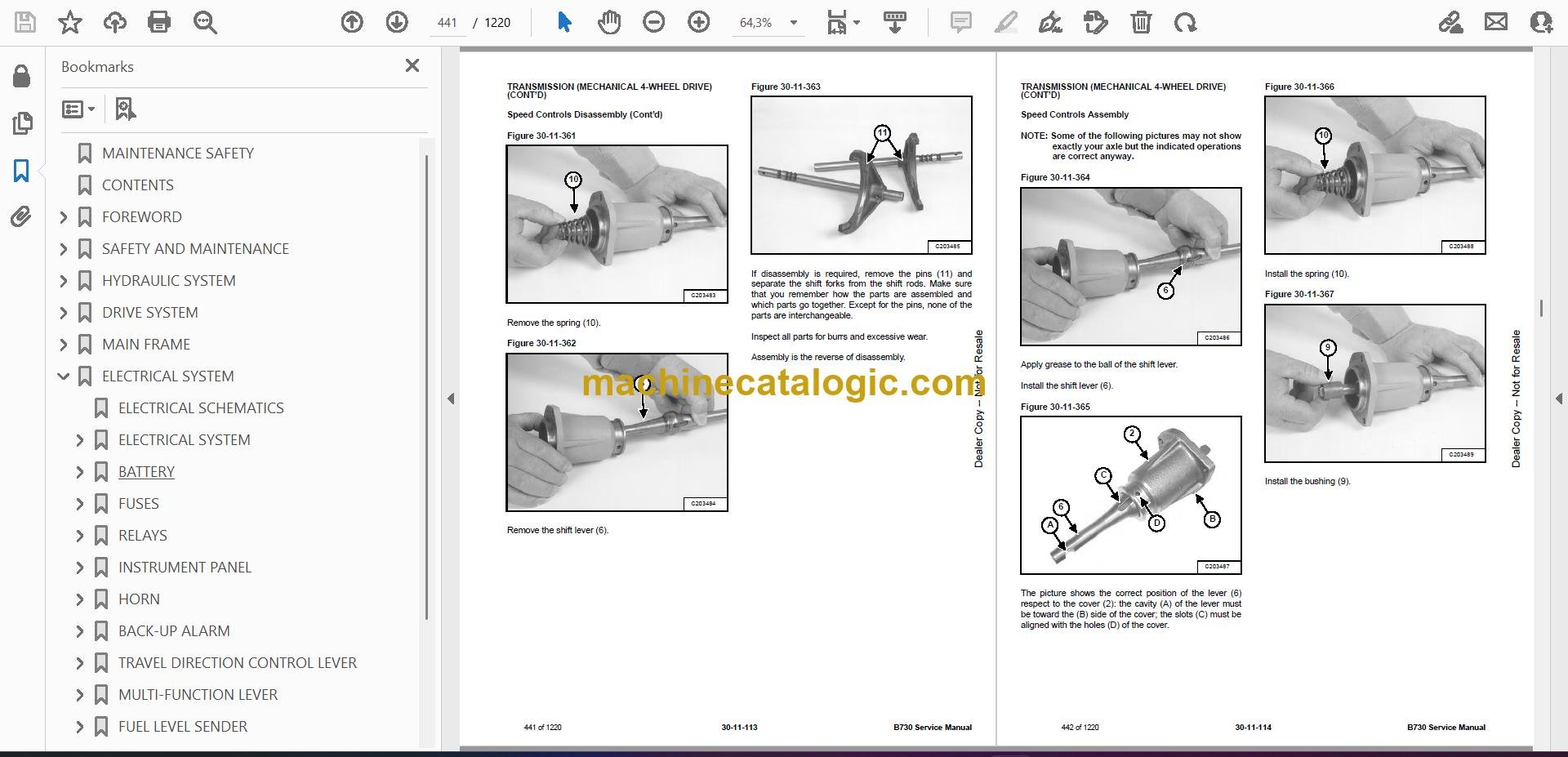
A: Yes, this type of manual is normally a PDF you can search, and the wiring diagrams are laid out so you can zoom in and follow circuits.

Q: How do I know if it covers my exact B730?

A: Check your serial number plate. If it falls between B53R11000 and B53R99999, this is the right manual for your machine.

Q: Is this the right document if I'm doing real repairs, not just maintenance?

A: Yes, this is the workshop service manual, meant for full diagnostics and repair, not just basic maintenance schedules.

Bottom line: If your B730 serial number is in that B53R11000-B53R99999 range and you're doing your own repairs, this is the manual you want. If your serial is outside that range, skip it.

📘 Show Index

Table of Contents:

  • MAINTENANCE SAFETY
  • CONTENTS
  • FOREWORD
    • FOREWORD
    • SAFETY INSTRUCTIONS
      • Before Operation
      • Safe Operation Is The Operator’s Responsibility
      • Safe Operation Needs A Qualified Operator
      • Avoid Silica Dust
      • Dismantling And Disposal
      • General Safety Information
      • Crushing And Burning Prevention
      • Fire And Explosion Prevention
      • Machine Startup Safety
      • Engine Startup And Operating Safety
      • Machine Operating Safety
      • Machine Parking Safety
      • Machine Transporting Safety
      • Machine Towing Safety
      • Machine Maintenance Safety
      • During Maintenance
      • Hydraulic Lines And Hoses
    • PUBLICATIONS AND TRAINING RESOURCES
    • SERIAL NUMBER LOCATION
      • Backhoe Loader Serial Number
      • Engine Serial Number
      • Other Serial Numbers
    • DELIVERY REPORT
    • BOBCAT BACKHOE LOADER IDENTIFICATION
  • SAFETY AND MAINTENANCE
    • SERVICE SCHEDULE
      • Maintenance Intervals
      • Lubrication Chart
      • Inspection Checkbook
    • LIFTING AND BLOCKING THE MACHINE
      • Procedure
    • TOWING THE MACHINE
      • Procedure
    • TRANSPORTING THE BACKHOE LOADER ON A TRAILER
      • Loading And Unloading
    • STOPPING THE ENGINE AND LEAVING THE MACHINE
    • STORAGE AND RETURN TO SERVICE
      • Storage
      • Return To Service
    • OPERATOR CAB
      • Description
      • Cab Doors
      • Windshield Wipers
      • Side Windows
      • Rear Windows
    • EMERGENCY EXIT
    • BACKHOE BOOM / SWING LOCK
      • Locking And Unlocking The Backhoe Boom / Swing Lock
    • APPROVED LIFT ARM SUPPORT DEVICE
      • Description
      • Installing The Approved Lift Arm Support Device
      • Removing The Approved Lift Arm Support Device
    • TIRE MAINTENANCE
      • Wheel Nuts
      • Rotating The Tires
      • Wheel Replacement
      • Mounting The Tires
      • Tire Pressure
    • ENGINE COVER
      • Opening And Closing
    • GRILLE
      • Removing And Installing
    • ENGINE AIR CLEANER
      • Description
      • Cleaning The Outer Air Filter
      • Replacing The Air Filters
    • FUEL SYSTEM
      • Fuel Specifications
      • Biodiesel Blend Fuel
      • Filling The Fuel Tank
      • Draining The Fuel Tank
      • Fuel Filters
    • ENGINE LUBRICATION SYSTEM
      • Engine Oil Chart
      • Checking And Adding Engine Oil
      • Removing And Replacing Oil And Filter
    • ENGINE COOLING SYSTEM
      • Cooling System
      • Cleaning The Cooling System
      • Checking And Adding Coolant
      • Removing And Replacing Coolant
    • HYDRAULIC SYSTEM
      • Hydraulic / Hydrostatic Fluid Chart
      • Checking And Adding Hydraulic Fluid
      • Removing And Replacing The Hydraulic Filters
      • Removing And Replacing The Hydraulic Fluid
    • REAR AXLE
      • Axle And Reduction Gears
      • Checking And Adding Oil
      • Draining Oil
      • Check And Adding Reduction Gear Oil
      • Draining Reduction Gear Oil
      • Parking Brake Inspection / Adjustment
    • TRANSMISSION
      • Checking And Adding Oil
      • Removing And Replacing Oil
      • Replacing The Filter Element
    • ALTERNATOR AND FAN BELT
      • Belt Checking
      • Belt Adjustment
      • Belt Replacement
    • ATTACHMENT COUPLING SYSTEMS
      • Loader Attachment Coupling Inspection And Maintenance
      • Backhoe Attachment Coupling Inspection And Maintenance
    • LUBRICATING THE MACHINE
      • Lubrication Locations
  • HYDRAULIC SYSTEM
    • HYDRAULIC / HYDROSTATIC SCHEMATICS
    • HYDRAULIC SYSTEM INFORMATION
      • Glossary Of Hydraulic / Hydrostatic Symbols
    • HYDRAULIC SYSTEM
      • Tests And Hydraulic Pressure Test
      • Test Ports
      • Blocks
      • ON-OFF Solenoid Valve
      • ON-OFF Pressure Reducing Valve
      • Steering Priority Valve
      • Steering Pressure Test
      • Pilot Pressure Test
      • Pilot Pressure Regulation Block
      • Priority Valve
    • RETURN LINE CHECK VALVE
      • Removal And Installation
    • LOADER ARM LIFT CYLINDERS
      • Removal And Installation
      • Parts Identification
      • Disassembly
      • Inspection
      • Assembly
    • LOADER BUCKET (TILT) CYLINDER
      • Removal And Installation
      • Parts Identification
      • Disassembly
      • Inspection
      • Assembly
    • CLAMPSHELL CYLINDER
      • Removal And Installation
      • Parts Identification
      • Disassembly
      • Inspection
      • Assembly
    • BACKHOE BOOM CYLINDER
      • Removal And Installation
      • Parts Identification
      • Disassembly
      • Inspection
      • Assembly
    • BACKHOE ARM CYLINDER
      • Removal And Installation
      • Parts Identification
      • Disassembly
      • Inspection
      • Assembly
    • BACKHOE BUCKET CYLINDER
      • Removal And Installation
      • Parts Identification
      • Disassembly
      • Inspection
      • Assembly
    • TELESCOPIC ARM CYLINDER
      • Removal And Installation
      • Parts Identification
      • Disassembly
      • Inspection
      • Assembly
    • BACKHOE SWING CYLINDERS
      • Removal And Installation
      • Parts Identification
      • Disassembly
      • Inspection
      • Assembly
    • BACKHOE STABILIZER CYLINDERS
      • Removal And Installation
      • Parts Identification
      • Disassembly
      • Inspection
      • Assembly
    • SIDE SHIFT LOCK CYLINDERS
      • Removal And Installation
    • HYDRAULIC PUMP
      • Description
      • Removal And Installation
    • BACKHOE CONTROL VALVE
      • Port Locations (ISO Pattern)
      • Removal And Installation
    • BRAKE PEDAL AND BOOSTER
      • Removal And Installation
    • HYDRAULIC FLUID RESERVOIR
      • Description
      • Removal And Installation
      • Hydraulic Fluid Screen Removal And Installation
      • Hydraulic Filter Removal And Installation
      • Hydraulic Suction Strainer Removal And Installation
    • LOADER CONTROL VALVE
      • Port Locations (Mechanical Controls)
      • Port Locations (Pilot Controls)
      • Removal And Installation
      • Pressure Relief Valves (PRV) Test And Unloading Valve Test
    • STEERING COLUMN AND UNIT
      • Removal And Installation
    • BACKHOE DISTRIBUTOR BLOCK
      • Removal And Installation
  • DRIVE SYSTEM
    • TRANSMISSION (MECHANICAL 2-WHEEL DRIVE)
      • Description
      • Removal And Installation
      • Tightening Torques
      • Plugs And Filters Disassembly
      • Plugs And Filters Assembly
      • Converter And Oil Pump Disassembly
      • Converter And Oil Pump Assembly
      • Pipes Disassembly
      • Pipes Assembly
      • Hydraulic Control Valve Disassembly
      • Hydraulic Control Valve Assembly
      • Transmission Housing Disassembly
      • Transmission Housing Assembly
      • Shafts A – D Disassembly
      • Shafts A – D Assembly
      • Shafts B – C Disassembly
      • Shafts B – C Assembly
      • Speed Controls Disassembly
      • Speed Controls Assembly
      • Troubleshooting
    • TRANSMISSION (MECHANICAL 4-WHEEL DRIVE)
      • Description
      • Removal And Installation
      • Tightening Torques
      • Plugs And Filters Disassembly
      • Plugs And Filters Assembly
      • Converter And Oil Pump Disassembly
      • Converter And Oil Pump Assembly
      • Pipes Disassembly
      • Pipes Assembly
      • Hydraulic Control Valve Disassembly
      • Hydraulic Control Valve Assembly
      • 4-Wheel Drive Solenoid Valve Disassembly
      • 4-Wheel Drive Solenoid Valve Assembly
      • Transmission Housing Disassembly
      • Transmission Housing Assembly
      • Shafts A – D Disassembly
      • Shafts A – D Assembly
      • Shafts B – C Disassembly
      • Shafts B – C Assembly
      • Shaft E Disassembly
      • Shaft E Assembly
      • Speed Controls Disassembly
      • Speed Controls Assembly
      • Troubleshooting
    • TRANSMISSION (AUTOSHIFT 4-WHEEL DRIVE)
      • Description
      • Removal And Installation
      • Tightening Torques
      • Filters Disassembly
      • Filters Assembly
      • Check Ports
      • Oil Pump Disassembly
      • Oil Pump Assembly
      • Switches And Sensors Disassembly
      • Switches And Sensors Assembly
      • Hydraulic Control Valve Disassembly
      • Hydraulic Control Valve Assembly
      • SAHR Brake Solenoid Valve Disassembly
      • SAHR Brake Solenoid Valve Assembly
      • SAHR Brake Group Disassembly
      • SAHR Brake Group Assembly
      • Manual Parking Brake Disassembly
      • Manual Parking Brake Assembly
      • Front Half-Housing Disassembly
      • Front Half-Housing Assembly
      • Rear Cover – Shafts Disassembly
      • Rear Cover – Shafts Assembly
      • Gear Pistons Disassembly
      • Gear Pistons Assembly
      • Speed Gears Shift Rails Adjustment
      • Speed Gears Switches Check
      • Shafts A – D Disassembly
      • Shafts A – D Assembly
      • Shafts B – C Disassembly
      • Shafts B – C Assembly
      • 4-Wheel Drive Shaft Disassembly
      • 4-Wheel Drive Shaft Assembly
      • Shift Rails – Forks Disassembly
      • Shift Rails – Forks Assembly
      • SAHR Parking Brake
      • 4WS Front Half-Housing Disassembly
      • 4WS Front Half-Housing Assembly
      • 4-Wheel Drive Shaft – Coaxial TLB1 Disassembly
      • 4-Wheel Drive Shaft – Coaxial TLB1 Assembly
    • FRONT AXLE (2-WHEEL DRIVE)
      • Description
      • Removal And Installation
      • Tightening Torques
      • Steering Cylinder Group Disassembly
      • Steering Cylinder Group Assembly
      • Wheel Hub Group Disassembly
      • Wheel Hub Group Assembly
      • Axle Beam Group Disassembly
      • Axle Beam Group Assembly
      • Toe-In Adjustment
      • Troubleshooting
    • FRONT AXLE (4-WHEEL DRIVE)
      • Description
      • Removal And Installation
      • Tightening Torques
      • Steering Cylinder Group Disassembly
      • Steering Cylinder Group Assembly
      • Epicyclic Reduction Gear Group Disassembly
      • Epicyclic Reduction Gear Group Assembly
      • Wheel Hub Group Disassembly
      • Wheel Hub Group Assembly
      • Differential Support Group Disassembly
      • Differential Support Group Assembly
      • Bevel Gear Marking Test
      • Differential Group Disassembly
      • Differential Group Assembly
      • Pinion Group Disassembly
      • Pinion Group Assembly
      • Axle Beam Group Disassembly
      • Axle Beam Group Assembly
      • Toe-In / Steering Angle
      • Toe-In Adjustment
      • Steering Angle Adjustment
      • Wheel And Double U-Joint Group Disassembly
      • Wheel And Double U-Joint Group Assembly
      • Double U-Joint Seal Ring Replacement On Axle Beam Side
      • Double U-Joint Bushing Replacement On Axle Beam Side
      • Testing After Assembly
      • Troubleshooting
    • REAR AXLE
      • Description
      • Removal And Installation
      • Tightening Torques
      • Parking Brake Caliper Group Disassembly
      • Parking Brake Caliper Group Assembly
      • Epicyclic Reduction Gear Group Disassembly
      • Epicyclic Reduction Gear Group Assembly
      • Wheel Hub Group Disassembly
      • Wheel Hub Group Assembly
      • Axle Beam Trumpet Group Disassembly
      • Axle Beam Trumpet Group Assembly
      • Brake Group Disassembly
      • Brake Group Assembly
      • Differential Support Group Disassembly
      • Differential Support Group Assembly
      • Differential Group Disassembly
      • Differential Group Assembly
      • Differential Locking Group Disassembly
      • Differential Locking Group Assembly
      • Pinion Group Disassembly
      • Pinion Group Assembly
      • Testing After Assembly
      • Troubleshooting
    • FRONT SHAFT
      • Removal And Installation
    • REAR SHAFT
      • Removal And Installation
    • SERVICE BRAKE
      • Description
      • Bleeding The Brake Circuitry
      • Test Procedure
      • Troubleshooting
  • MAIN FRAME
    • BACKHOE BOOM / SWING LOCK
      • Removal And Installation
    • BUCKET TEETH
      • Removal And Installation
    • BACKHOE BOOM
      • Removal And Installation
    • CAB (PILOT CONTROL)
      • Removal And Installation
    • CAB (MECHANICAL CONTROL)
      • Removal And Installation
    • COUNTERWEIGHT
      • Removal And Installation
    • ENGINE COVER
      • Removal And Installation
    • FRONT MUDGUARD
      • Removal And Installation
    • PARKING LEVER
      • Removal And Installation
    • FUEL TANK
      • Removal And Installation
    • KINGPOST
      • Removal And Installation
    • SIDE SHIFT
      • Removal And Installation
    • BACKHOE ARM
      • Removal And Installation
    • FRONT CONSOLE
      • Removal And Installation
    • STABILIZER WEAR PADS
      • Adjustment
  • ELECTRICAL SYSTEM
    • ELECTRICAL SCHEMATICS
    • ELECTRICAL SYSTEM
      • Component Location
    • BATTERY
      • Battery Maintenance
      • Battery Testing
      • Battery Charging
      • Using A Booster Battery (Jump Starting)
      • Removing And Installing The Battery
      • Battery Disconnect Switch
    • FUSES
      • Location
      • Parts Identification (Synchroshuttle Transmission)
      • Parts Identification (Autoshift Transmission)
    • RELAYS
      • Location
      • Parts Identification (Synchroshuttle Transmission)
      • Parts Identification (Autoshift Transmission)
    • INSTRUMENT PANEL
      • Removal And Installation
    • HORN
      • Removal And Installation
    • BACK-UP ALARM
      • Inspection
      • Removal And Installation
    • TRAVEL DIRECTION CONTROL LEVER
      • Removal And Installation
      • Parts Identification
    • MULTI-FUNCTION LEVER
      • Removal And Installation
    • FUEL LEVEL SENDER
      • Removal And Installation
  • ENGINE SERVICE (TIER 2)
    • ENGINE INFORMATION
      • Introduction
      • Engine Views
      • Engine Identification
      • Safety Precautions
      • Safety Precautions When The Engine Is Cleaned
      • Engine Lift Equipment
      • Viton Seals
      • POWERPART Recommended Consumable Products
      • Troubleshooting
    • ENGINE SPECIFICATIONS
      • Basic Engine Data
      • Data And Dimensions
      • Thread Sealant
      • Standard Torque Values
      • Specific Torque Values
      • Compression Test Data
    • CYLINDER HEAD
      • General Description
      • Atomiser Cover
      • Rocker Cover
      • Rocker Arm
      • Valve Tip Clearances
      • Valve Springs
      • Removal
      • Installation
      • Valve And Valve Springs
      • Valve Guides
      • Inspection And To Correct
    • PISTON AND CONNECTING ROD ASSEMBLIES
      • General Description
      • Big End Bearing
      • Piston And Connecting Rod
      • Piston Rings
      • Piston And Connecting Rod Assembly
      • Piston And Piston Rings
      • Connecting Rod
      • Partially Finished Small End Bush
      • Piston Cooling Jets
    • CRANKSHAFT ASSEMBLY
      • General Description
      • Crankshaft Pulley
      • Rear End Oil Seal Assembly
      • To Remove And To Fit A Wear Sleeve
      • Thrust Washers
      • Main Bearings
      • Crankshaft
      • Balancer Unit
    • TIMING CASE AND DRIVE ASSEMBLY
      • General Description
      • Timing Cover
      • Mechanical Fuel Pump Gear
      • Electronic Fuel Pump Gear
      • Idler Gear and Hub
      • Heavy Duty Idler Gear
      • Camshaft Gear
      • Front Oil Seal
      • Timing Case
      • Crankshaft Gear
      • Camshaft And Tappets
    • CYLINDER BLOCK ASSEMBLY
      • General Description
      • Cylinder Block
      • Cylinder Bore
    • ENGINE TIMING
      • General Description
      • To Set Number 1 Piston To TDC On The Compression Stroke
      • To Check The Timing Of The Bosch VP30 Fuel Injection Pump
      • To Check The Timing Of The Bosch EPVE Fuel Injection Pump
      • To Adjust The Timing Of The Bosch EPVE Fuel Injection Pump
      • To Check The Timing Of The Delphi DP210 Fuel Injection Pump
      • To Check The Valve Timing
    • ASPERATION SYSTEM
      • General Description
      • Exhaust Elbow
      • Turbocharger Side Mount
      • Turbocharger Faults
      • Open Engine Breather
      • Natural Aspirated Engine Breather
      • Closed Engine Breather
    • LUBRICATION SYSTEM
      • General Description
      • Lubrication System Flow Diagram
      • Canister Type Oil Filter
      • Element Type Oil Filter
      • Filter Head
      • Sump
      • Dipstick Tube
      • Oil Strainer And Suction Pipe
      • Lubricating Oil Pump Assembly
      • Relief Valve
    • FUEL SYSTEM
      • General Description
      • Cold Start Advance Unit (KSB)
      • Typical Fuel System
      • Fuel Filter Assembly
      • Atomizers
      • Fuel Lift Pump And Filter Assembly
      • Removing Air From The Fuel System
      • Bosch VP30 Fuel Injection Pump
      • Bosch EVPE Fuel Injection Pump
      • Delphi DP210 Fuel Injection Pump
    • ENGINE COOLING SYSTEM
      • General Description
      • Coolant Flow Diagram
      • Thermostat
      • Coolant Pump
      • Fan
      • Fan Drive
      • Lubricating Oil Cooler
      • Coolant Bypass Pipe
      • Oil Cooler / Radiator Removal And Installation
      • Expansion Tank Removal And Installation
    • FLYWHEEL AND HOUSING
      • General Description
      • Flywheel
      • Ring Gear
      • Flywheel Housing
    • ELECTRICAL SYSTEM
      • General Description
      • Alternator
      • Starter Motors
      • Starting Aid (Glow Plug)
      • Electrical Components
      • Engine Control Module (ECM)
      • Voltage Load Protection Module
      • Programming A New ECM
      • Speed And Timing Sensor
      • Pressure Sensor
      • Temperature Sensor
      • Wiring Harness
    • AUXILIARY EQUIPMENT
      • General Description
      • Power Steering Pump
      • Adaptor For A Hydraulic Pump Or A Steering Pump
      • Exhauster
    • SPECIAL TOOLS
    • ENGINE
      • Removal And Installation
    • ACCELERATOR PEDAL
      • Removal And Installation
      • Cable Removal And Installation
      • Cable Adjustment
    • EXHAUST
      • Removal And Installation
    • ENGINE AIR CLEANER
      • Removal And Installation
  • HEATING, VENTILATION AND AIR CONDITIONING (HVAC)
    • HVAC UNIT
      • Removal And Installation
  • SPECIFICATIONS
    • BACKHOE LOADER SPECIFICATIONS
      • Machine Dimensions
      • Loader Performance
      • Backhoe Performance
      • Fork Performance
      • Controls
      • Brakes
      • Engine
      • Hydraulic System
      • Electrical System
      • Drive System
      • Steering
      • Axles
      • Tyres
      • Operating Weight
      • Capacities
      • Cab
      • Instrument Panel
      • Temperature Range
    • MACHINE TORQUE SPECIFICATIONS
      • Drive Line
      • Cab
      • Wheels
    • TORQUE SPECIFICATIONS FOR BOLTS
      • Torque For General SAE Bolts
      • Torque For General Metric Bolts
    • HYDRAULIC CONNECTION SPECIFICATIONS
      • O-ring Face Seal Connection
      • Straight Thread O-ring Fitting
      • Tubelines And Hoses
      • Flare Fitting
      • O-ring Flare Fitting
      • Port Seal Fitting
    • REGULAR MAINTENANCE ITEMS
      • Parts
      • Fluids, Lubricants And Fuel
    • CONVERSIONS
      • Decimal And Millimeter Equivalent Chart
      • U.S. To Metric Conversion Chart
    • SERVICE TOOLS REQUIRED
      • Mechanical Tools
      • Hydraulic Tools
      • Electrical Tools
  • ALPHABETICAL INDEX

Bobcat Software

Bobcat PDF Manuals

Related Manuals

0
    0
    Your Cart
    Your cart is emptyReturn to Shop