$ 0
0
$ 0
0

Bobcat 3400XL Utility Vehicle Service Manual (SN B3FM11001-B3FM99999)

Format: PDF (Printable Document)

File Language: English

File Pages: 487

File Size: 14.15 MB (Speed Download Link)

Brand: Bobcat

Model: 3400XL Utility Vehicle

Book No: 7255694

Serial No: SN B3FM11001-B3FM99999

Type of Document: Service Manual

Categories: ,

$ 45

Share:

Bobcat 3400XL Utility Vehicle Service Manual (SN B3FM11001-B3FM99999)

The 3400XL is the farm and ranch runaround: fencing, spot spraying, hauling tools, dragging small trailers. When something quits, the person who ends up with the service manual is the one who has to get it back in service before Monday. They're trying to figure out why it won't start, why it won't move, or how to tear into a system without guessing and breaking more parts. That's where this kind of book earns its keep.

What this manual helps you do

  • Diagnose no-start, hard-start, or poor running by following engine and fuel system checks
  • Trace electrical faults with wiring diagrams and step-by-step test procedures
  • Check and repair drivetrain problems like no-move, slipping, or odd noises from the transaxle
  • Replace and adjust steering, suspension, and brake parts with correct sequences and specs
  • Troubleshoot hydraulic dump or accessory issues and verify things are working right after repair

Who this is for

This manual is for a 3400XL owner-operator, farm shop, small contractor, or rental fleet that wants to do real repairs, not just basic checks. If you only want to know button functions, fluid types, and simple maintenance intervals, you want the operator's handbook instead, not this service manual.

FAQ

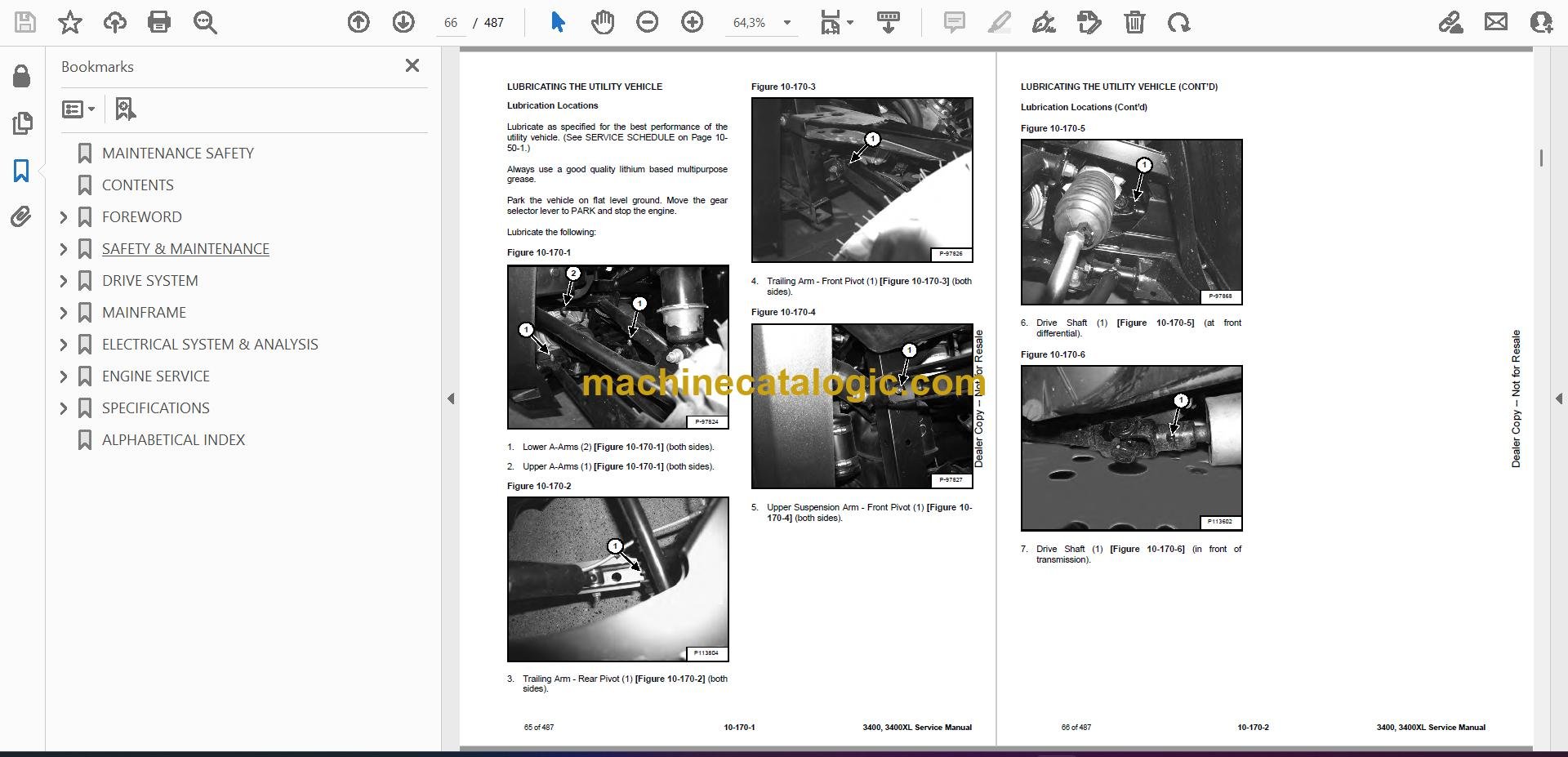
Q: Is this a searchable PDF and are the wiring diagrams readable?

A: Yes, it's a PDF you can search, and the wiring diagrams are laid out so you can zoom in to follow circuits and color codes.

Q: Does this cover my exact 3400XL?

A: It's written for 3400XL utility vehicles in the serial number range B3FM11001 through B3FM99999. If your plate falls in that range, this is the right one.

Q: Is this the right book if I'm doing real repairs, not just oil changes?

A: Yes. This is the workshop service manual, meant for teardown, testing, and reassembly, not routine daily checks.

Bottom line: If your 3400XL serial number is between B3FM11001 and B3FM99999 and you plan to wrench on it yourself, this is the manual you want.

📘 Show Index

Table of Contents:

  • MAINTENANCE SAFETY
  • CONTENTS
  • FOREWORD
    • FOREWORD
    • SAFETY INSTRUCTIONS
    • FIRE PREVENTION
      • Maintenance
      • Operation
      • Electrical
      • Fueling
      • Starting
      • Spark Arrester Exhaust System
      • Welding And Grinding
      • Fire Extinguishers
    • SERIAL NUMBER LOCATIONS
      • Utility Vehicle Serial Number
      • Engine Serial Number
    • DELIVERY REPORT
    • UTILITY VEHICLE IDENTIFICATION (3400)
    • UTILITY VEHICLE IDENTIFICATION (3400XL)
  • SAFETY & MAINTENANCE
    • LIFTING AND BLOCKING THE UTILITY VEHICLE
      • Procedure
    • ROLLOVER PROTECTIVE STRUCTURE (ROPS)
      • Description
    • TRANSPORTING THE UTILITY VEHICLE ON A TRAILER
      • Loading And Unloading
      • Fastening
    • TOWING THE UTILITY VEHICLE
      • Procedure
    • SERVICE SCHEDULE
      • Maintenance Intervals
    • AIR CLEANER SERVICE
      • Pre-Filter Element
      • Replacing Filter Element
    • ENGINE COOLING SYSTEM
      • Checking Level
      • Cleaning
      • Removing And Replacing Coolant
    • FUEL SYSTEM
      • Fuel Specifications
      • Biodiesel Blend Fuel
      • Filling The Fuel Tank
      • Fuel Filter
      • Removing Air From The Fuel System
      • Filling A Portable Fuel Container
    • ENGINE LUBRICATION SYSTEM
      • Checking And Adding Engine Oil
      • Engine Oil Chart
      • Removing And Replacing Oil And Filter
    • CONTINUOUS VARIABLE TRANSMISSION (CVT)
      • CVT Drying
      • CVT Filter
    • GEARCASE
      • Checking Transmission Fluid
      • Transmission Fluid
      • Adding Transmission Fluid
      • Removing And Replacing Transmission Fluid
      • Checking Front Gearcase Fluid
      • Front Gearcase Fluid
      • Adding Front Gearcase Fluid
      • Removing And Replacing Front Gearcase Fluid
    • TIRE MAINTENANCE
      • Tires
      • Tire Tread Depth
      • Axle And Wheel Nut Torque
      • Wheel Removal And Installation
      • Mounting
      • Tire Pressure
    • SPARK ARRESTER MUFFLER
      • Cleaning Procedure
    • UTILITY VEHICLE STORAGE AND RETURN TO SERVICE
      • Storage
      • Return To Service
    • STOPPING THE ENGINE AND LEAVING THE UTILITY VEHICLE
      • Procedure
    • SEAT BELT
      • Inspection And Maintenance
    • LUBRICATING THE UTILITY VEHICLE
      • Lubrication Locations
  • DRIVE SYSTEM
    • BRAKE
      • General Specifications
      • Torque Specifications
      • System Service Notes
      • Noise Troubleshooting
      • System Troubleshooting
      • Hydraulic Brake System Operation
      • System Parts Identification
      • Master Cylinder Removal And Installation
      • Foot Brake Pedal Removal And Installation
      • Bleeding / Fluid Removal And Installation
      • Brake Inspection
      • Brake Pad Inspection
      • Burnishing
    • BRAKE (FRONT)
      • Pad Removal
      • Pad Inspection
      • Pad Assembly / Installation
      • Caliper Removal
      • Caliper Parts Identification
      • Caliper Disassembly
      • Caliper Inspection
      • Caliper Assembly
      • Caliper Installation
      • Disc Runout
      • Disc Inspection
      • Disc Removal And Installation
    • BRAKE (REAR)
      • Caliper Removal
      • Pad Removal
      • Pad Inspection
      • Pad Installation
      • Caliper Parts Identification
      • Caliper Disassembly
      • Caliper Inspection
      • Caliper Assembly
      • Caliper Installation
      • Disc Runout
      • Disc Inspection
      • Disc Removal And Installation
    • TRANSMISSION
      • General Operation
      • System Troubleshooting
      • Shift Lever Removal And Installation
      • Shift Cable Inspecting
      • Shift Cable Adjustment
      • Shift Cable Removal And Installation
      • Removal
      • Installation
      • Parts Identification
      • Transmission Disassembly
      • Gear Cluster Disassembly
      • Snorkel Shaft Removal / Disassembly
      • Planetary Differential Disassembly
      • Planetary Differential Assembly
      • Snorkel Gear Backlash
      • Transmission Assembly
    • DRIVE BELT
      • Removal
      • Installation
      • Belt Inspection
      • Belt Damage
    • CONTINUOUS VARIABLE TRANSMISSION (CVT)
      • CVT System Overview
      • Drive Clutch Operation
      • Driven Clutch Operation
      • CVT Break-In (Drive Belt / Clutches)
      • Maintenance And Inspection
      • Overheating Troubleshooting
      • System Troubleshooting
      • CVT Sealing, Guard And Ducting Components Parts Identification
      • CVT (Outer) Cover Removal And Installation
      • CVT (Inner) Cover Removal And Installation
    • CONTINUOUS VARIABLE TRANSMISSION (CVT) (DRIVE CLUTCH)
      • Removal And Installation
      • Spring Specifications
      • Parts Identification
      • Disassembly
      • Assembly
    • CONTINUOUS VARIABLE TRANSMISSION (CVT) (DRIVEN CLUTCH)
      • Removal And Installation
      • Parts Identification
      • Disassembly
      • Assembly
    • FINAL DRIVE
      • Description
      • Bearing Carrier Removal
      • Bearing Removal And Installation
      • Bearing Carrier Installation
      • Front Drive Shaft Removal And Installation
      • Rear Drive Shaft Removal And Installation
      • Drive Shaft / CV Joint Handling
      • Outer CV Joint And Boot Removal And Installation
      • Inner Plunging Joint And Boot Removal And Installation
      • Propshaft Removal And Installation
      • Propshaft U-Joint Disassembly
      • Propshaft U-Joint Assembly
      • Front Gearcase Operation
      • Front Gearcase Removal And Installation
      • Front Gearcase Parts Identification
      • Front Gearcase Disassembly / Inspection
      • Front Gearcase Assembly
  • MAINFRAME
    • ROLL OVER PROTECTIVE STRUCTURE (ROPS)
      • Removal And Installation
    • OPERATOR SEAT
      • Seat Back Removal And Installation
      • Seat Base Removal And Installation
      • Seat Belt Removal And Installation
    • DASH
      • Front Access Cover Removal And Installation
      • Upper Dash Panel Removal And Installation
      • Lower Dash Panel Removal And Installation
      • Storage Panel Removal And Installation
    • BUMPER COVER
      • Removal And Installation
    • REAR SUSPENSION LINK AND AXLE BRACE
      • Upper Suspension Link Removal And Installation
      • Lower Suspension Link Removal And Installation
      • Axle Brace Removal And Installation
      • Rear Axle Bearing Replacement
    • STEERING COLUMN
      • Description
      • Tilt Steering Shock Removal And Installation
      • Parts Identification
      • Steering Wheel Removal And Installation
      • Steering Wheel / Upper Steering Shaft Removal And Installation
      • Steering Shaft Bearing Replacement
      • Power Steering Unit Removal
      • Power Steering Unit Installation
    • STEERING BOX
      • Removal And Installation
    • FUEL TANK
      • Removal And Installation
    • SHOCKS
      • Rear Shock Removal And Installation
      • Front Shock Removal And Installation
      • Shock Spring Removal And Installation
    • A-ARMS
      • Lower A-Arm Removal And Installation
      • Upper A-Arm Removal
      • Upper A-Arm Installation
      • Inspection
      • Ball Joint Removal And Installation
    • TIE ROD
      • Description
      • Removal And Installation
      • Toe Adjustment Procedure
    • TAILGATE
      • Removal And Installation
      • Latch Removal And Installation
    • CARGO BOX
      • Removal And Installation
    • FENDER
      • Removal And Installation (Front)
      • Removal And Installation (Rear)
      • Flare Removal And Installation
  • ELECTRICAL SYSTEM & ANALYSIS
    • ELECTRICAL SCHEMATICS
    • ELECTRICAL SYSTEM INFORMATION
      • Glossary Of Electrical Symbols
      • Troubleshooting
      • Description
      • Fuse And Relay Location
    • BATTERY
      • Removal And Installation
      • Servicing
      • Using A Booster Battery (Jump Starting)
    • CHARGING SYSTEM
      • Current Draw – Key OFF
      • Break Even Test
      • Alternator Removal And Installation
      • Belt Adjustment
      • Belt Replacement
    • STARTER SYSTEM
      • Operation
      • Testing
      • Removal And Installation
    • FUEL SOLENOID
      • Location
      • Removal And Installation
      • Testing
    • LIGHTS
      • Headlight Removal And Installation
      • Headlight Adjustment
      • Taillight / Brake Light Removal And Installation
    • ELECTRONIC CONTROL MODULE (ECU)
      • Description
      • Removal And Installation
    • VEHICLE SPEED SENSOR
      • Location
      • Testing
    • SWITCH (HEADLIGHT)
      • Location
      • Removal And Installation
      • Testing
    • SWITCH (BRAKE LIGHT)
      • Description
      • Location
      • Removal And Installation
      • Testing
    • SWITCH (AWD / 2WD / TURF)
      • Location
      • Removal And Installation
      • Testing
    • SWITCH (KEY)
      • Location
      • Removal And Installation
      • Ignition Key Switch Testing
    • SWITCH (GEAR SELECTOR)
      • Location
      • Removal And Installation
      • Testing
    • GLOWPLUGS
      • Location
      • Removal And Installation
      • Testing
    • DIFFERENTIAL SOLENOID
      • Description
      • Removal And Installation
    • DIFFERENTIAL SOLENOID (REAR RELAY)
      • Description
      • Removal And Installation
    • BACK-UP ALARM SYSTEM (IF EQUIPPED)
      • Description
      • Inspecting
      • Removal And Installation
    • TEMPERATURE SENSOR
      • Description
      • Testing
      • Removal And Installation
      • Fan Control Circuit Operation / Testing
      • Fan Control Circuit Bypass Test
    • INSTRUMENT CLUSTER
      • Information Display
      • Pinouts
      • Information Display Area
      • Diagnostic Trouble Codes
      • Removal And Installation
    • FUEL SENDER
      • Testing
    • DIAGNOSTIC TESTING
      • Digital Wrench™ Diagnostic Software
      • Digital Wrench™ Diagnostic Connector
      • Digital Wrench™ SmartLink Module Kit – MEL1721
      • Serial Number Location
      • Version And Update ID
      • Updates
      • Digital Wrench™ Feature Map
      • Engine Controller Reprograming (Reflash)
    • ELECTRONIC POWER STEERING (EPS)
      • EPS Operation
      • Power Steering 30A Fuse
      • System Diagnosing
      • EPS Troubleshooting (Power Steering Non-Functional with MIL ON)
      • EPS Troubleshooting (Power Steering Non-Functional with MIL OFF)
      • EPS Troubleshooting (Using Digital Wrench™)
  • ENGINE SERVICE
    • ENGINE INFORMATION
      • Description
      • Specifications
      • Torque Values
      • Troubleshooting
      • Accessible Engine Components
      • Engine Removal And Installation
      • Engine Installation Notes
      • Engine Mount Replacement
      • Compression And Leakage Test
      • Cylinder Head Diagnostics
      • Fuel Limiter
      • Idle Speed Setting
      • Timing Belt Inspection
    • THROTTLE SYSTEM
      • Throttle Pedal Removal And Installation
      • Throttle Cable Removal And Installation
      • Throttle Freeplay
      • Inspection And Maintenance
      • Throttle Freeplay Adjustment
    • MUFFLER
      • Removal And Installation
    • AIR CLEANER
      • Housing Removal And Installation
    • ENGINE COOLING SYSTEM
      • Cooling System Pressure Test
      • Radiator Cap Pressure Test
      • System Bleeding
      • Radiator Cleaning
      • Radiator Removal And Installation
      • Cooling Fan Removal And Installation
      • Thermostat Removal And Installation
      • Water Pump Removal And Installation
    • LUBRICATION SYSTEM
      • Oil Pan Removal And Installation
      • Oil Pump Removal
      • Oil Pump Inspection
      • Oil Pump Installation
      • Engine Oil Pressure – Testing
    • FUEL SYSTEM
      • Service Notes
      • Operation
      • Initial Priming / Starting Procedure
      • Fuel Line Removal / Installation
      • Fuel Tank Removal
      • Fuel Tank Installation
      • Fuel Pump
      • Fuel Sender
      • Injector Timing
    • ENGINE DISASSEMBLY AND INSPECTION
      • Crankcase Vacuum Regulator Valve Removal
      • Intake Manifold Removal
      • Exhaust Manifold Removal
      • Drive Pulley Removal
      • Flywheel Removal
      • Timing Belt Removal
      • Timing Pulleys Removal
      • Water Pump Removal
      • Speed Governor Removal
      • Rocker Arm Cover Removal
      • Fuel Rail Removal
      • Unit Injector Removal
      • Rocker Arm Assembly Removal
      • Camshaft Removal
      • Camshaft Inspection
      • Cylinder Head Removal
      • Valve Removal
      • Valve And Spring Inspection
      • Pre-Combustion Chamber Removal
      • Piston And Connecting Rod Removal
      • Piston And Piston Ring Inspection
      • Connecting Rod Inspection
      • Cylinder Inspection
      • Crankshaft Removal
      • Crankshaft Inspection
    • ENGINE ASSEMBLY
      • Crankshaft Installation
      • Piston And Connecting Rod Installation
      • Oil Pan Installation
      • Pre-Combustion Chamber Installation
      • Valve Installation
      • Cylinder Head Installation
      • Camshaft Installation
      • Rocker Arm Assembly Installation
      • Valve / Rocker Arm Clearance
      • Speed Governor Installation
      • Unit Injector Installation
      • Fuel Rail Installation
      • Rocker Arm Cover Installation
      • Oil Pump Installation
      • Water Pump Installation
      • Timing Pulleys Installation
      • Timing Belt Installation
      • Flywheel Installation
      • Drive Pulley Installation
      • Starter Installation
      • Exhaust Manifold Installation
      • Intake Manifold Installation
      • Crankcase Vacuum Regulator Valve Installation
  • SPECIFICATIONS
    • 3400 UTILITY VEHICLE SPECIFICATIONS
      • Dimensions (S/N B3FK16999 & Below)
      • Dimensions (S/N B3FK17001 & Above)
      • (3400XL) Dimensions (S/N B3FM16999 & Below)
      • (3400XL) Dimensions (S/N B3FM17001 & Above)
      • Performance
      • Controls
      • Engine
      • Electrical
      • Drive System
      • Fluid And Capacities
      • Tires
    • TECHNICAL SERVICE GUIDE SPECIFICATIONS
      • Engine
      • Engine Torques
      • Cooling System
    • TORQUE SPECIFICATIONS FOR BOLTS
      • Torque For General SAE Bolts
      • Torque For General Metric Bolts
    • CONVERSIONS
      • Decimal And Millimeter Equivalent Chart
      • U.S. To Metric Conversion Chart
    • SERVICE TOOLS REQUIRED
      • Hydraulic Tools
      • Transmission / Clutch / Drive Tools
      • Engine Tools
      • HVAC Tools
  • ALPHABETICAL INDEX

Bobcat Software

Bobcat PDF Manuals

Related Manuals

0
    0
    Your Cart
    Your cart is emptyReturn to Shop