$ 0
0
$ 0
0

Bobcat TL4380HF VersaHANDLER® TTC, Telescopic Handler Service Manual (SN B4BY11001-B4BY99999)

Format: PDF (Printable Document)

File Language: English

File Pages: 822

File Size: 28.63 MB (Speed Download Link)

Brand: Bobcat

Model: TL4380HF VersaHANDLER® TTC, Telescopic Handler

Book No: 7318405

Serial No: SN B4BY11001-B4BY99999

Type of Document: Service Manual

Categories: ,

$ 45

Share:

Bobcat TL4380HF VersaHANDLER® TTC, Telescopic Handler Service Manual (SN B4BY11001-B4BY99999)

A TL4380HF VersaHANDLER is the kind of telehandler you see on a jobsite unloading trucks, setting trusses, or stacking pallets in a tight yard. The people who grab this service manual are the ones turning wrenches: small contractors, field techs like me, and shop mechanics. They're trying to chase down hydraulic issues, sort electrical gremlins, or rebuild something without guessing and ordering parts twice. This specific book is for the TL4380HF telescopic handler with serial numbers in the B4BY11001 to B4BY99999 range.

What this manual helps you do

  • Diagnose hydraulic problems, check pressures, and track down slow or weak boom and stabilizer functions
  • Trace and repair electrical faults using wiring diagrams, connector callouts, and harness routing info
  • Follow step-by-step teardown and reassembly for boom components, axles, and driveline parts in the shop or in the dirt
  • Adjust linkages, boom wear pads, and steering components so the machine runs straight and lifts correctly
  • Replace major components like pumps, motors, and cylinders with the right removal, install, and setup procedures

Who this is for

If you own or maintain a TL4380HF VersaHANDLER in that B4BY11001-B4BY99999 serial range, this is the right workshop manual. It fits small contractors, rental fleets, owner-operators, and techs who already know which end of a multimeter to hold. If you just need basic controls or daily checks, you want the operator's handbook instead.

FAQ

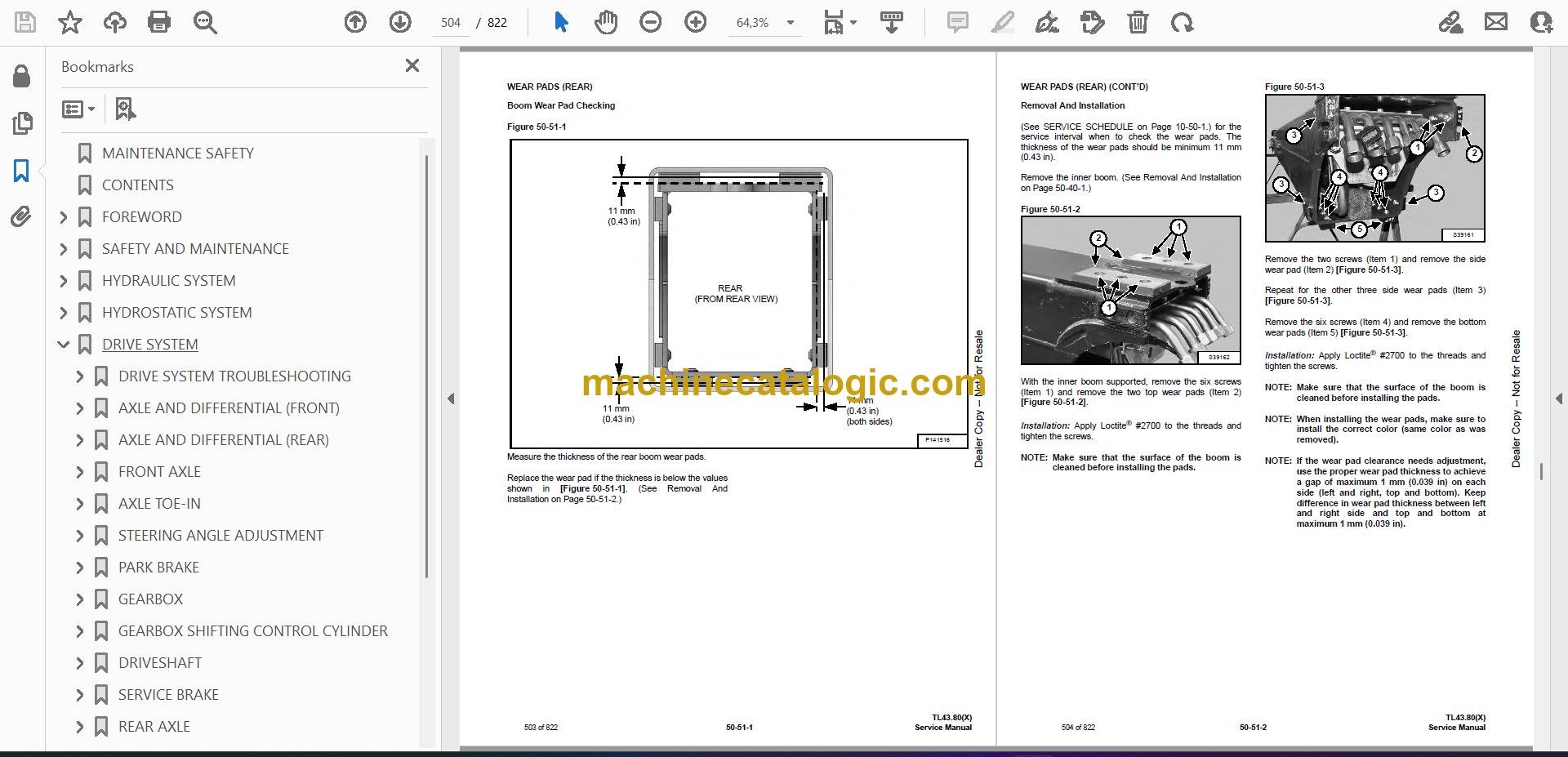
Q: Is this a searchable PDF with clear wiring diagrams?

A: These manuals are usually supplied as searchable PDFs, and the wiring diagrams are normally clean enough to zoom in on connector labels and wire colors.

Q: How do I know if it covers my exact machine?

A: Check your serial plate; if it starts with B4BY and falls between B4BY11001 and B4BY99999, this manual matches your machine variant.

Q: Is this the right document if I'm planning real repairs, not just maintenance?

A: Yes, this is the workshop service manual, meant for diagnostics and repair, not just fluid changes and walk-around checks.

Bottom line, if your TL4380HF's serial number is in that B4BY range and you're doing your own repairs, this is the manual you want. If the serial does not match, skip it.

📘 Show Index

Table of Contents:

  • MAINTENANCE SAFETY
  • CONTENTS
  • FOREWORD
    • FOREWORD
    • SAFETY INSTRUCTIONS
      • Safe Operation Is The Operator’s Responsibility
      • Safe Operation Needs A Qualified Operator
      • Avoid Silica Dust
      • Dismantling And Disposal
    • FIRE PREVENTION
      • Maintenance
      • Operation
      • Electrical
      • Hydraulic System
      • Fueling
      • Starting
      • Welding And Grinding
      • Fire Extinguishers
    • PUBLICATIONS AND TRAINING RESOURCES
    • SERIAL NUMBER LOCATION
      • Telescopic Handler Serial Number
      • Telescopic Handler Statutory Plate
      • Engine Serial Number
      • Other Serial Numbers
    • DELIVERY REPORT
    • BOBCAT TELESCOPIC HANDLER IDENTIFICATION
  • SAFETY AND MAINTENANCE
    • LIFTING AND BLOCKING THE TELESCOPIC HANDLER
      • Procedure
    • OPERATOR CAB
      • Description
      • Cab Door
      • Cab Door Window
      • Rear Cab Window
      • Cab Light
    • TRANSPORTING THE TELESCOPIC HANDLER ON A TRAILER
      • Loading And Unloading
      • Fastening
    • TOWING THE TELESCOPIC HANDLER
      • Procedure
    • SERVICE SCHEDULE
      • Maintenance Intervals
    • AIR CLEANER SERVICE
      • Replacing Filter Elements
    • COOLING SYSTEM
      • Cleaning
      • Checking Level
      • Removing And Replacing The Coolant
    • FUEL SYSTEM
      • Fuel Specifications
      • Biodiesel Blend Fuel
      • Filling The Fuel Tank
      • Fuel Pre-Filter
      • Fuel Filter
      • Removing Air From The Fuel System
    • ENGINE LUBRICATION SYSTEM
      • Checking And Adding Engine Oil
      • Engine Oil Chart
      • Removing And Replacing Oil And Filter
      • Removing And Replacing Oil Separator Filter
    • HYDRAULIC / HYDROSTATIC SYSTEM
      • Checking And Adding Fluid
      • Hydraulic / Hydrostatic Fluid
      • Removing And Replacing Hydraulic Fluid
      • Removing And Replacing Hydraulic / Hydrostatic Filters
      • Removing And Replacing Hydraulic Charge Filter
      • Fill / Breather Cap
      • Hydraulic Fluid Air Bleeding Procedure
      • Starter Procedure
    • AXLES (FRONT AND REAR)
      • Checking And Adding Oil (Planetary Carrier)
      • Removing And Replacing Oil (Planetary Carrier)
      • Checking And Adding Oil (Rear Differential)
      • Removing And Replacing Oil (Rear Differential)
      • Checking And Adding Oil (Front Differential)
      • Removing And Replacing Oil (Front Differential)
      • Checking And Adding Oil (Gearbox)
      • Removing And Replacing Oil (Gearbox)
    • LUBRICATING THE TELESCOPIC HANDLER
      • Lubrication Locations
    • ATTACHMENT CARRIER
      • Inspection And Maintenance
    • TIRE MAINTENANCE
      • Wheel Nuts
      • Rotating
      • Wheel Replacement
      • Mounting
      • Pressure
    • APPROVED BOOM STOP
      • Installing The Approved Boom Stop
      • Removing The Approved Boom Stop
    • ENGINE COVER
      • Opening And Closing
    • STOPPING THE ENGINE AND LEAVING THE TELESCOPIC HANDLER
      • Procedure
    • EMERGENCY EXIT
      • Rear Window
      • Right Rear Window
    • TELESCOPIC HANDLER STORAGE AND RETURN TO SERVICE
      • Storage
      • Return To Service
    • LIFTING THE TELESCOPIC HANDLER
      • Procedure
    • REMOTE START TOOL (SERVICE TOOL) KIT – 6987761
      • Remote Start Tool (Service Tool) – 7022042
      • Telescopic Handler Service Tool Harness – 6689747
      • Computer Service Tool Harness – 6689746
      • Remote Start Procedure
  • HYDRAULIC SYSTEM
    • HYDRAULIC / HYDROSTATIC SCHEMATICS
    • HYDRAULIC SYSTEM INFORMATION
      • Glossary Of Hydraulic / Hydrostatic Symbols
      • Troubleshooting Chart
      • Tightening Procedures
    • BOOM CYLINDER
      • Removal And Installation
      • Parts Identification
      • Disassembly
      • Assembly
    • SELF LEVELING (COMPENSATION) CYLINDER
      • Removal And Installation
      • Parts Identification
      • Disassembly
      • Assembly
    • EXTENSION (COMPENSATION) CYLINDER
      • Cylinder Group Removal And Installation
      • Upper Tubeline Removal And Installation
      • Extension Cylinder Removal And Installation
      • Tubeline Tray Disassembly
      • Parts Identification
      • Disassembly
      • Assembly
    • TILT CYLINDER
      • Removal And Installation
      • Parts Identification
      • Disassembly
      • Assembly
    • STEERING CYLINDER (FRONT / REAR)
      • Removal
      • Installation
      • Disassembly
      • Assembly
    • COLLECTOR BLOCK
      • Removal And Installation
      • Parts Identification
      • Disassembly And Assembly
    • SERVICE BRAKE VALVE
      • Removal And Installation
    • LS PISTON PUMP ELECTRONIC TORQUE CONTROL
      • LS Piston Pump Testing
      • Troubleshooting Chart (LS Piston Pump Testing)
      • Servo Piston Testing
      • Removal And Installation
      • Parts Identification
      • Disassembly And Assembly
    • FAN MOTOR
      • Description
      • Removal And Installation
      • Parts Identification (Single Speed Version) (Standard)
      • Disassembly And Assembly (Single Speed Version) (Standard)
      • Parts Identification (Variable Speed Version)
      • Disassembly And Assembly (Variable Speed Version)
    • HYDRAULIC FLUID TANK
      • Removal And Installation
    • STEERING UNIT
      • Removal And Installation
    • MAIN VALVE
      • Troubleshooting Chart (Controllers)
      • Valve Section Troubleshooting
      • Troubleshooting Chart (Main Valve)
      • Main Relief Valve Removal And Installation
      • Removal And Installation
      • Parts Identification
      • Disassembly And Assembly
      • End Housing Disassembly And Assembly
      • Auxiliary Valve Section Disassembly And Assembly
      • Telescoping Valve Section Disassembly And Assembly
      • Tilting Valve Section Disassembly And Assembly
      • Lifting Valve Section Disassembly And Assembly
      • Inlet-Outlet Valve Section Disassembly And Assembly
    • PORT RELIEF VALVES
      • Testing
      • Replacement Procedure
    • ACCUMULATORS
      • Accumulators Pressure Relief
      • Park / Service Brake Accumulator Removal And Installation
      • LS Pump Accumulator Removal And Installation
    • FAN PUMP
      • Description
      • Removal And Installation
      • Parts Identification
      • Disassembly And Assembly
    • POWER LIFT SYSTEM
      • Description
      • Removing And Installing The Self Leveling Valve
      • Removing And Installing The Power Lift Valve
    • TRAILER BRAKE VALVE
      • Description
      • Removal And Installation
    • BOOM SUSPENSION AND FLOAT SYSTEM
      • Boom Suspension Functional Description
      • Boom Float Functional Description
      • Removing And Installing The Boom Suspension Valve
  • HYDROSTATIC SYSTEM
    • HYDROSTATIC SYSTEM INFORMATION
      • Troubleshooting Chart
      • Replenishing Valve Function
      • Drive Component Location
      • Test Coupler Location
    • OIL COOLER
      • Description
    • HYDROSTATIC DRIVE MOTOR
      • Removal And Installation
      • Parts Identification
      • Disassembly
      • Inspection
      • Assembly
    • HYDROSTATIC PUMP
      • Removal And Installation
      • Parts Identification
      • Shaft Disassembly
      • Relief Valves Disassembly And Assembly
      • Charge Pump Disassembly
      • Piston Pump Disassembly
      • Solenoid Block Disassembly
      • Inspection
      • Piston Pump Assembly
      • Charge Pump Assembly
      • Solenoid Block Assembly
      • Shaft Assembly
    • CHARGE PRESSURE
      • Description
      • Testing And Adjusting
    • MULTIFUNCTION VALVES
      • Description
      • Testing
  • DRIVE SYSTEM
    • DRIVE SYSTEM TROUBLESHOOTING
      • Chart
    • AXLE AND DIFFERENTIAL (FRONT)
      • Description
      • Planetary Carrier And Drive Axle Parts Identification
      • Planetary Carrier Disassembly
      • Steering Knuckle Parts Identification
      • Steering Knuckle Disassembly
      • Drive Axle Disassembly
      • Brake Group Parts Identification
      • Brake Group Disassembly
      • Differential And Pinion Group Parts Identification
      • Differential Disassembly
      • Pinion Group Disassembly
      • Pinion Group Assembly
      • Differential Assembly
      • Brake Group Assembly
      • Drive Axle Assembly
      • Steering Knuckle Assembly
      • Planetary Carrier Assembly
    • AXLE AND DIFFERENTIAL (REAR)
      • Description
      • Planetary Carrier And Drive Axle Parts Identification
      • Planetary Carrier Disassembly
      • Steering Knuckle Parts Identification
      • Steering Knuckle Disassembly
      • Differential And Pinion Group Parts Identification
      • Differential Disassembly
      • Pinion Group Disassembly
      • Pinion Group Assembly
      • Differential Assembly
      • Steering Knuckle Assembly
      • Planetary Carrier Assembly
    • FRONT AXLE
      • Removal And Installation
    • AXLE TOE-IN
      • Adjustment
    • STEERING ANGLE ADJUSTMENT
      • Adjustment
    • PARK BRAKE
      • Releasing The Brake For Towing
      • Adjustment
      • Brake Cylinder Removal
      • Brake Cylinder Disassembly And Assembly
      • Brake Disc Removal And Installation
      • Brake Cylinder Installation
    • GEARBOX
      • Removal And Installation
      • Parts Identification
      • Disassembly
      • Assembly
    • GEARBOX SHIFTING CONTROL CYLINDER
      • Removal
      • Parts Identification
      • Disassembly
      • Assembly
      • Installation
    • DRIVESHAFT
      • Rear Driveshaft Removal And Installation
      • Front Driveshaft Removal And Installation
    • SERVICE BRAKE
      • Description
      • Bleeding The Brake Circuit
    • REAR AXLE
      • Removal And Installation
  • MAINFRAME
    • OPERATOR CAB
      • Removal And Installation
    • OPERATOR SEAT
      • Removal And Installation
    • FIXED BOOM
      • Removal
      • Installation
    • INNER BOOM
      • Removal And Installation
    • WEAR PADS (FRONT)
      • Boom Wear Pad Checking
      • Removal And Installation
    • WEAR PADS (REAR)
      • Boom Wear Pad Checking
      • Removal And Installation
    • ENGINE COVER
      • Gas Cylinder Removal And Installation
      • Removal And Installation
    • FUEL TANK
      • Removal And Installation
    • ATTACHMENT CARRIER (QUICK-TACH)
      • Removal And Installation
    • ATTACHMENT CARRIER (MER-TACH)
      • Removal And Installation
      • Setting Up The Attachment
    • COUNTERWEIGHT
      • Removal And Installation
    • FENDER
      • Removal And Installation
    • STEERING COLUMN COVER
      • Removal And Installation
    • DASH COVER
      • Removal And Installation
    • JOYSTICK PANEL
      • Removal And Installation
  • ELECTRICAL SYSTEM AND ANALYSIS
    • ELECTRICAL SCHEMATICS
    • ELECTRICAL SYSTEM INFORMATION
      • Glossary Of Electrical Symbols
      • Cab Harness Connectors
      • Mainframe Harness Connectors
      • Engine Bay Harness Connectors
      • Engine Bay Harness Connectors
      • DEF Harness Connectors
      • Engine Harness Connectors
      • Troubleshooting Chart
      • Description
      • Fuses And Relay Location / Identification
    • BATTERY
      • Battery Maintenance
      • Using A Booster Battery (Jump Starting)
      • Removing And Installing The Battery
    • ALTERNATOR
      • Belt Adjustment
      • Belt Checking
      • Belt Replacement
      • Removal And Installation
    • STARTER
      • Testing
      • Removal And Installation
    • LIGHTS
      • Rear Light Removal And Installation
      • Front Light Removal And Installation
      • Rear Work Light Removal And Installation
    • SIGNAL LEVER
      • Removal And Installation
    • DISPLAY
      • Removal And Installation
    • INSTRUMENT PANELS
      • Right Instrument And Indicator Panel Removal And Installation
      • Left Instrument Panel Removal And Installation
    • BOOM ANGLE SENSOR
      • Description
      • Removal And Installation
    • FRONT WIPER MOTOR
      • Removal And Installation
    • TOP WIPER MOTOR
      • Removal And Installation
    • REAR WIPER MOTOR
      • Removal And Installation
    • SERVICE BRAKE PEDAL ASSEMBLY
      • Removal And Installation
    • INCHING SENSOR
      • Description
      • Removal And Installation
    • EMERGENCY BRAKE
      • Description
    • SERVICE PC (LAPTOP COMPUTER)
      • Connecting Remote Start Tool (Service Tool) – 6987761
    • FUEL LEVEL SENDER
      • Removal And Installation
    • JOYSTICK
      • Removal And Installation
    • LLMI / LLMC SYSTEM
      • System Components Identification
      • Longitudinal Load Moment Indicator (LLMI) Description
      • Longitudinal Load Moment Controller (LLMC)
      • Longitudinal Load Moment Controller (LLMC) Override Switch
      • LLMS Removal
      • LLMS Installation
    • MAINTENANCE CLOCK
      • Description
      • Setup
      • Reset
    • CONTROLLERS
      • Description
      • Gateway Controller
      • Drive Controller
      • Workgroup Controller
      • Display Controller
      • LLMI Controller
      • LLMC Controller
      • Engine Controller
      • Dosing Controller
    • RETRACT SENSOR
      • Removal And Installation
      • Adjustment
    • AUTOMATIC PARK BRAKE
      • Description
    • CALIBRATION
      • Calibrating The Hydrostatic Pump
      • Calibrating The Boom Angle Sensor
      • Calibrating The Inching Sensor
      • Calibrating The LLMC System
      • LLMC Calibration Test
      • LLMI / LLMC System Failure Reports
  • ENGINE SERVICE
    • ENGINE
      • Description
      • Sensor Locations
      • Troubleshooting
      • Removal And Installation
    • ENGINE BAY ASSEMBLY
      • Removal And Installation
    • ENGINE SPEED CONTROL
      • Removal And Installation
    • EXHAUST PIPE
      • Removal And Installation
    • AIR CLEANER
      • Housing Removal And Installation
    • COOLING SYSTEM
      • Hydraulic Oil Cooler / Intercooler / Radiator Removal And Installation
      • Expansion Tank Removal And Installation
      • Cooling System Check
      • Cooling System Inspection
    • SELECTIVE CATALYTIC REDUCTION (SCR) SYSTEM
      • Description
      • Diesel Exhaust Fluid (DEF) / AdBlue® Level
      • DeSOX Process
      • SCR System Codes
      • Diesel Exhaust Fluid (DEF) / AdBlue® Unsatisfactory Quality
      • SCR System Component Tampering
      • EGR Impeded
      • Diesel Exhaust Fluid (DEF) / AdBlue® Dosing Interruption
      • Removal And Installation
      • Dosing Module Removal And Installation
    • DIESEL OXIDATION CATALYST (DOC)
      • Removal And Installation
    • EXHAUST GAS RECIRCULATION (EGR) SYSTEM
      • Description
    • TURBOCHARGER
      • Description
    • DIESEL EXHAUST FLUID (DEF) TANK
      • Removal And Installation
      • DEF Tank Fan Removal And Installation
      • Coolant Valve Removal And Installation
      • Dosing Control Unit (DCU) Removal And Installation
      • Supply Module Removal And Installation
      • Supply Module Filter Removal And Installation
    • FUEL COOLER
      • Removal And Installation
  • HEATING, VENTILATION, AIR CONDITIONING (HVAC)
    • AIR CONDITIONING SYSTEM FLOW
      • Description
      • Chart
      • Components
      • Safety Equipment
    • REGULAR MAINTENANCE
      • Filters
      • Air Conditioning Belt Adjustment
      • Belt Replacement
      • Cleaning The Condenser
      • Air Conditioning Lubrication
      • Air Conditioning Service Chart
      • Evaporator / Heater Coil
    • A/C SYSTEM TROUBLESHOOTING
      • Blower Motor Does Not Operate
      • Blower Motor Operates Normally, But Air Flow Is Insufficient
      • Insufficient Cooling Although Air Flow And Compressor Operation Are Normal
      • The Compressor Does Not Operate At All, Or Operates Improperly
      • Gauge Pressure Related Troubleshooting
      • Temperature / Pressure Chart
      • Poor A/C Performance
      • HVAC Repair And Leaks
      • Electrical System
    • SYSTEM CHARGING AND RECLAMATION
      • Reclamation And Charging With Recovery / Charging Unit
    • COMPRESSOR
      • Removal And Installation
      • Oil
      • Oil Check
      • Clutch Disassembly And Assembly
    • CONDENSER
      • Removal And Installation
    • RECEIVER / DRIER
      • Removal And Installation
    • PRESSURE SWITCH
      • Removal And Installation
    • EVAPORATOR / HEATER UNIT
      • Removal And Installation
    • THERMOSTAT
      • Description
      • Removal And Installation
    • EXPANSION VALVE
      • Removal And Installation
  • SPECIFICATIONS
    • (TL43.80(X)) TELESCOPIC HANDLER SPECIFICATIONS
      • Machine Dimensions
      • Performance
      • Weights
      • Engine
      • Controls
      • Drive System
      • Traction
      • Steering
      • Brakes
      • Fluid Capacities
      • Hydraulic System
      • Electrical System
      • Temperature Range
      • Altitude
      • Instrument Panel
      • Environmental
      • Visibility Diagrams
      • Visibility Diagrams For Light Material Buckets
      • Lifting
      • Tie Down
    • MACHINE TORQUE SPECIFICATIONS
      • Axle
      • Boom
      • Drive Box
      • Drive Motor
      • Engine
      • Hydraulic Pump
    • TORQUE SPECIFICATIONS FOR BOLTS
      • Torque for General SAE Bolts
      • Torque For General Metric Bolts
    • HYDRAULIC CONNECTION SPECIFICATIONS
      • O-ring Face Seal Connection
      • Straight Thread O-ring Fitting
      • Tubelines And Hoses
      • Flare Fitting
      • O-ring Flare Fitting
      • Port Seal Fitting
    • HYDRAULIC / HYDROSTATIC FLUID SPECIFICATIONS
      • Specifications
    • CONVERSIONS
      • Decimal And Millimeter Equivalent Chart
      • U.S. To Metric Conversion Chart
    • SERVICE TOOLS REQUIRED
      • Remote Start Tools
      • Hydraulic Tools
      • Drive Tools
      • Electrical Tools
      • Engine Tools
      • Special Drive Tools
  • ALPHABETICAL INDEX

Bobcat Software

Bobcat PDF Manuals

Related Manuals

0
    0
    Your Cart
    Your cart is emptyReturn to Shop