$ 0
0
$ 0
0

Bobcat 341 Excavator Service Manual (SN 230611001-230699999)

Format: PDF (Printable Document)

File Language: English

File Pages: 492

File Size: 17.65 MB (Speed Download Link)

Brand: Bobcat

Model: 341 Excavator

Book No: 6900380

Serial No: SN 230611001-230699999

Type of Document: Service Manual

Categories: ,

$ 45

Share:

Bobcat 341 Excavator Service Manual (SN 230611001-230699999)

A Bobcat 341 is a compact excavator that spends its life trenching, loading trucks, and working tight spots where a big machine won't fit. The people who grab this service manual are the ones actually turning wrenches: shop mechanics, field techs, and owners who'd rather fix than haul to the dealer. They're looking for teardown steps, test specs, and wiring info so the machine goes back out clean at the next 50/250/500-hour slot, not on a hook.

What this manual helps you do

  • Diagnose no-start, low-power, or smoking complaints on the small diesel and confirm what to check before you order parts
  • Trace hydraulic problems like weak boom, slow travel, or swing drift and pressure-test circuits on the 341's hydraulic system
  • Follow step-by-step disassembly and reassembly on drive motors, cylinders, control valves, and swing components so you don't miss seals or shims
  • Check and set adjustments for controls, pilot pressures, and travel functions so the machine tracks straight and responds correctly
  • Replace and wire in sensors, switches, and harness sections using readable wiring diagrams and connector callouts

Who this is for

This is for anyone maintaining or repairing a Bobcat 341 excavator in the serial range 230611001 to 230699999: small contractors, rental fleets, owner-operators, and shop techs. If you're just learning how to run the machine or want safety/operating tips, you need the operator's handbook instead, not this service manual.

FAQ

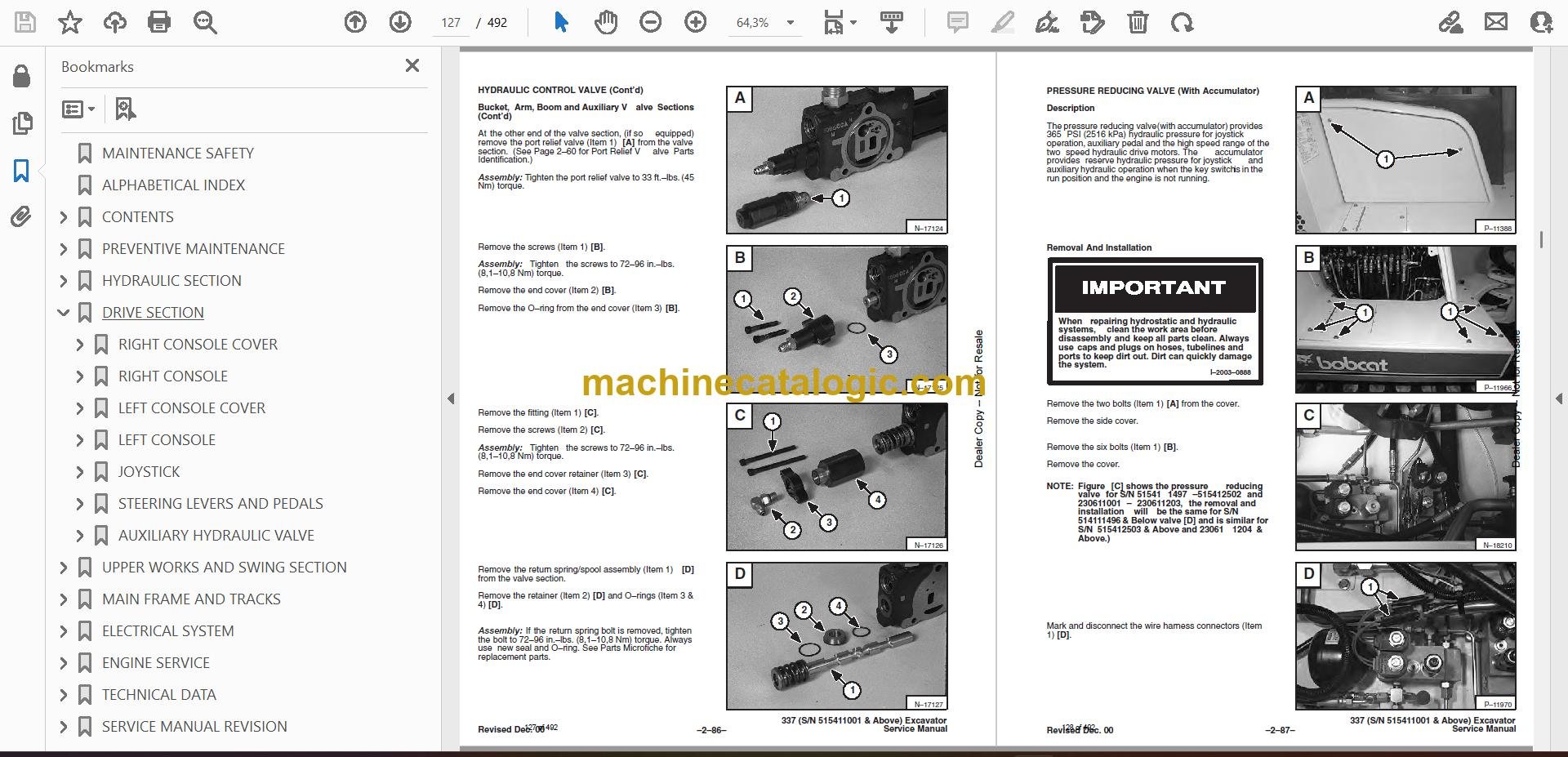
Q: Is this a searchable PDF and are the wiring diagrams readable?

A: Yes, this is typically a searchable PDF, and the wiring diagrams are laid out so you can zoom in and read pin numbers and wire colors.

Q: How do I know if it fits my exact 341?

A: Check your serial plate. If your 341 serial number falls between 230611001 and 230699999, this is the right manual.

Q: I just want maintenance intervals and fluid types. Is this overkill?

A: For simple daily/50-hour checks, yes, it's more than you need. For real diagnostics, repairs, and rebuilds, this is the right document.

Bottom line: If you own or service a Bobcat 341 in that serial range and you're doing real repairs, this is the manual you want. If you only need basic operating info, skip it.

📘 Show Index

Table of Contents:

  • MAINTENANCE SAFETY
  • ALPHABETICAL INDEX
  • CONTENTS
    • FOREWORD
    • SAFETY INSTRUCTIONS
    • SERIAL NUMBER LOCATIONS
    • HYDRAULIC EXCAVATOR SERIAL NUMBER
    • ENGINE SERIAL NUMBER
    • DELIVERY REPORT
    • HYDRAULIC EXCAVATOR IDENTIFICATION
  • PREVENTIVE MAINTENANCE
    • SERVICE SCHEDULE
    • LIFTING AND BLOCKING THE EXCAVATOR
      • Procedure
    • TRANSPORTING THE HYDRAULIC EXCAVATOR
      • Procedure
    • ENGINE COVER
      • Opening The Engine Cover
      • Adjusting The Engine Cover Latches
    • AIR CLEANER
      • Air Cleaner Service
    • FUEL SYSTEM
      • Fuel Specifications
      • Filling The Fuel Tank
      • Fuel System Maintenance
      • Fuel Filter Service
      • Removing Air From The Fuel System
    • ENGINE LUBRICATION SYSTEM
      • Checking Engine Oil
      • Replacing Oil And Filter
    • COOLING SYSTEM
      • Coolant Level
      • Replacing Coolant
      • Propylene Glycol (Factory Installed)
    • ALTERNATOR BELT
      • Adjustment
    • HYDRAULIC SYSTEM
      • Checking And Adding Fluid
      • Replacing The Hydraulic Fluid
      • Replacing the Hydraulic Filter
      • Replacing The Case Drain Filter
    • SPARK ARRESTOR MUFFLER (If Equipped)
      • Cleaning Procedure
    • TRAVEL MOTOR
      • Checking Oil Level
      • Draining And Refilling
    • LUBRICATION OF THE HYDRAULIC EXCAVATOR
      • Procedure
    • HEATER AIR FILTER (With Cab Option Only)
      • Cleaning Procedure
  • HYDRAULIC SECTION
    • HYDRAULIC SCHEMATICS
    • HYDRAULIC SYSTEM TROUBLESHOOTING
    • HYDRAULIC SERVICE INFORMATION
      • Description
    • HYDRAULIC PUMPS
      • Testing The Hydraulic Gear Pump
      • Testing The Pump Stand By Circuit
      • Adjusting The Pump Stand By Circuit
      • Testing The Torque Limiter Load Sense Circuit
      • Testing The Pump Compensator
      • Adjusting The Pump Compensator
      • Testing The Torque Limiter For Pressure At Maximum Flow
      • Testing The Torque Limiter For Flow At Maximum Pressure
    • HYDRAULIC PISTON PUMP
      • Removal And Installation
      • Coupler Removal And Installation
      • Torque Limiter Valve Parts Identification
      • Torque Limiter Valve Removal
      • Torque Limiter Valve Disassembly
      • Torque Limiter Valve Assembly
      • Initial Torque Limiter Valve Setting
      • Torque Limiter Valve Installation
      • Parts Identification
      • Disassembly
      • Assembly
      • Pump Control Parts Identification
      • Pump Control Removal And Installation
      • Pump Control Disassembly
      • Pump Control Assembly
    • HYDRAULIC GEAR PUMP (S/N 515411001 –515412249 and 230611001 – 230611067)
      • Parts Identification
      • Disassembly
      • Assembly
    • HYDRAULIC GEAR PUMP
      • (S/N 515412250 & Above and 230611068 & Above)
      • Parts Identification
      • Disassembly
      • Assembly
    • MAIN RELIEF VALVES
      • Pressure Setting And Adjustment
      • Pressure Setting And Adjustment (3900 PSI)
      • Load Sense Relief Valve Setting (3450 PSI) (If Equipped)
      • Removal and Installation
    • PORT RELIEF VALVES
      • Port Relief Valve Pressure Setting
      • Parts Identification
      • Adjustment Procedure
    • HYDRAULIC CONTROL VALVE
      • Removal And Installation
      • Mid–Inlet Isolator Spool
      • Control Valve Identification
      • Disassembly and Assembly
      • Swing and Second Auxiliary Valve Section
      • Blade Valve Section
      • Mid–Inlet Valve Section
      • Load Sense Relief Valve Parts Identification
      • Boom Swing and Travel Valve Sections
      • Bucket, Arm, Boom and Auxiliary Valve Sections
    • PRESSURE REDUCING VALVE (With Accumulator)
      • Description
      • Removal And Installation
    • PRESSURE REDUCING VALVE (Without Accumulator)
      • Description
      • Removal And Installation
      • Parts Identification
      • Disassembly
      • Assembly
      • Testing
      • Testing (S/N 515411497 – 515412054 & 2306 11001–230611203)
      • Testing (S/N 515411496 & Below)
    • PRESSURE REDUCING VALVE (With and WithoutAccumulator) (S/N 515412053 & Above and 230611204 & Above)
      • Parts Identification
      • Disassembly
      • Assembly
      • Testing
      • Testing (With Accumulator)
      • Testing (Without Accumulator)
    • DUAL SEQUENCE VALVE
      • Removal and Installation
      • Disassembly and Assembly
    • AUXILIARY HYDRAULIC VALVE
      • Description
      • Removal And Installation
      • Foot Pedal Disassembly and Assembly (Later Model)
      • Foot Pedal Disassembly and Assembly (Early Model)
      • Disassembly
      • Assembly
    • BOOM SWING LOCK VALVE
      • Description
      • Removal And Installation
      • Parts Identification
      • Disassembly
      • Assembly
    • OIL COOLER
      • Removal And Installation
    • HYDRAULIC RESERVOIR
      • Removal And Installation
    • LIFTING CLAMP CYLINDER (If Equipped)
      • Removal And Installation
    • BOOM CYLINDER
      • Removal And Installation
      • Parts Identification
    • ARM CYLINDER
      • Removal And Installation
      • Parts Identification
    • BUCKET CYLINDER
      • Removal And Installation
      • Parts Identification
    • BLADE CYLINDER
      • Removal And Installation
      • Parts Identification
    • BOOM SWING CYLINDER
      • Removal And Installation
      • Parts Identification
    • HYDRAULIC CYLINDER
      • Disassembly
      • Assembly
    • JOYSTICK CONTROL CHANGE
      • ISO/Standard Control Pattern
    • CONTROL PATTERN SELECTOR VALVE
      • Disassembly
      • Assembly
    • AUXILIARY SELECTOR VALVE
      • Description
      • Removal And Installation
      • Disassembly And Assembly
  • DRIVE SECTION
    • RIGHT CONSOLE COVER
      • Removal And Installation
      • Arm Rest Removal And Installation
      • Gauge Removal And Installation
    • RIGHT CONSOLE
      • Swing Lock Lever Removal And Installation
      • Blade Lever Removal And Installation
      • Speed Control Lever Removal And Installation
      • Speed Control Lever Adjustment
    • LEFT CONSOLE COVER
      • Removal And Installation
      • Arm Rest Removal And Installation
      • Switch Removal And Installation
      • Rear Cover Removal And Installation
      • Heater Control Removal And Installation
    • LEFT CONSOLE
      • Console And Mount Removal And Installation
      • Control Lock Micro–switch Removal And Installation
      • Lock Lever Removal And Installation
      • Gas Spring Removal And Installation
      • Console Removal And Installation
    • JOYSTICK
      • Removal And Installation Of Right Hand Joystick
      • Removal And Installation Of Left Hand Joystick
      • Parts Identification
      • Disassembly
      • Assembly
      • Troubleshooting
    • STEERING LEVERS AND PEDALS
      • Removal And Installation
      • Adjusting The Linkage Cables
      • Disassembly And Assembly
    • AUXILIARY HYDRAULIC VALVE
      • Removal And Installation
  • UPPER WORKS AND SWING SECTION
    • ENGINE COVER
      • Removal And Installation
    • SEAT AND SEAT MOUNT
      • Removal And Installation
    • FLOORMAT AND FLOOR PLATE
      • Removal And Installation
    • REAR FLOOR PLATE
      • Removal And Installation
    • LEFT SIDE COVER
      • Removal And Installation
    • RIGHT SIDE COVER
      • Removal And Installation
    • RIGHT CORNER POST
      • Removal And Installation
    • LEFT CORNER POST
      • Removal And Installation
    • RIGHT COUNTERWEIGHT
      • Removal And Installation
    • LEFT COUNTERWEIGHT
      • Removal And Installation
    • BATTERY BOX
      • Removal And Installation
    • FUEL TANK
      • Removal And Installation
    • BUCKET TEETH
      • Removal And Installation
    • X–CHANGE™
      • Removal And Installation
    • ARM
      • Removal And Installation
    • BOOM
      • Removal And Installation
    • BOOM SWING BRACKET
      • Removal And Installation
      • Hose Installation
    • SWING BRACKET BUSHING
      • Bushing Removal
      • Bushing Installation
    • SWING MOTOR (S/N 515411496 & Below)
      • Removal And Installation
      • Parts Identification
      • Disassembly
      • Inspection
      • Assembly
    • SWING MOTOR DRIVE CARRIER (S/N 515411496 &Below)
      • Removal And Installation
      • Parts Identification
      • Disassembly
      • Assembly
    • SWING MOTOR/BRAKE ASSEMBLY (S/N 515411497& Above)
      • Removal And Installation
    • SWING MOTOR/BRAKE ASSEMBLY (S/N 515411497& Above)
      • Disassembly
      • Inspection
      • Assembly
    • SWING MOTOR DRIVE CARRIER (S/N 515411497 &Above)
      • Removal And Installation
      • Parts Identification
      • Checking The Drive Carrier Shaft End Play
      • Inspection
      • Assembly
    • FRONT ENGINE COVER
      • Removal And Installation
    • UPPERSTRUCTURE AND SWING CIRCLE GEAR
      • Removal And Installation
      • Swing Bearing Removal
      • Swing Bearing Installation
      • Upperstructure Installation
    • CENTER SWIVEL JOINT
      • Removal And Installation
      • Parts Identification
    • ROPS CANOPY
      • Removal And Installation
    • CAB
      • Removal And Installation
      • Heater Removal And Installation
      • Heater Disassembly And Assembly
      • Front Window Removal And Installation
      • Front Lower Window Removal And Installation
      • Front Upper Window Removal And Installation
      • Door Removal And Installation
      • Door Window Removal And Installation
      • Left Hand Side Window Removal And Installation
      • Right Hand Side Window Removal And Installation
      • Right Hand Window Assembly Removal AndInstallation
      • Rear Window Removal And Installation
    • CAB/CANOPY REAR COVER
      • Removal
      • Installation
  • MAIN FRAME AND TRACKS
    • BLADE
      • Removal And Installation
    • TRACK
      • Track Lug Height
      • Rubber Track Clearance
      • Rubber Track Adjustment
      • Steel Track Clearance
      • Steel Track Adjustment
      • Rubber Track Removal And Installation
      • Steel Track Removal
      • Steel Track Installation
      • Track Shoe Removal And Installation
    • TRACK FRAME
      • Disassembly And Assembly
    • TRACK IDLER
      • Parts Identification
      • Disassembly
      • Assembly
    • TRACK ROLLER
      • Parts Identification
      • Disassembly
      • Assembly
    • TRAVEL MOTOR
      • Testing (Case Drain)
      • Removal And Installation
      • Parts Identification
      • Disassembly
      • Assembly
    • TRACK DAMAGE IDENTIFICATION
      • Cutting Of Steel Cords
      • Abrasion Of Embedded Metals
      • Separation Of Embedded Metals
      • Separation Of Embedded Metals Due To Corrosion
      • Cuts On The Lug Side Rubber
      • Cracks On The Lug Side Rubber Due To Fatigue
      • Lug Abrasion
      • Cracks And Cuts On The Lug Side Rubber
      • Abrasion Of The Track Roller Side
      • Cuts On The Edges Of Track Roller Side
  • ELECTRICAL SYSTEM
    • ELECTRICAL SCHEMATICS
    • ELECTRICAL SYSTEM
      • Description
      • Troubleshooting
      • Electrical Relays And Diodes
      • Fuses
      • Electrical System Service
      • Using A Booster Battery (Jump Starting)
    • BATTERY
      • Removal And Installation
      • Servicing The Battery
    • ALTERNATOR
      • Belt Adjustment
      • Removal And Installation
      • Parts Identification
      • Disassembly And Inspection
      • Stator Continuity Test
      • Stator Ground Test
      • Rotor Continuity Test
      • Rotor Ground Test
      • Rectifier Continuity (Diode) Test
      • Assembly
    • STARTER
      • Removal And Installation
      • Parts Identification
      • Disassembly
      • Inspection And Repair
      • Assembly
    • FUEL LEVEL SENDER
      • Removal And Installation
      • Testing And Inspection
    • GAUGES
      • Removal And Installation
      • Bulb Replacement
    • TWO SPEED SWITCH
      • Removal And Installation
    • HORN
      • Removal And Installation
    • BUZZER
      • Removal And Installation
    • TIMER
      • Removal And Installation
    • DIODES
      • Diode Location
      • Diode Replacement
      • Diode Testing
    • CAB ELECTRICAL
      • Cab Option
    • TWO SPEED SWITCH
      • Removal and Installation (Later Models)
      • Removal and Installation (Early Models)
  • ENGINE SERVICE
    • TROUBLESHOOTING
      • Chart
    • VALVE CLEARANCE
      • Adjustment
    • ENGINE COMPRESSION
      • Checking
    • GLOW PLUGS
      • Removal And Installation
      • Checking The Glow Plug
    • FUEL SHUT–OFF SOLENOID
      • Adjustment
      • Removal And Installation
      • Timer Module Removal And Installation
    • FUEL INJECTION PUMP
      • Checking The Injection Pump
      • Removal And Installation
      • Timing The Injection Pump
    • FUEL INJECTOR NOZZLES
      • Removal And Installation
      • Checking The Injector Nozzle
    • FAN GUARD
      • Removal And Installation
    • RADIATOR
      • Removal And Installation
    • MUFFLER
      • Removal And Installation
    • AIR CLEANER
      • Removal And Installation
      • Air Cleaner Mount Removal And Installation
    • ENGINE
      • Removal And Installation
    • ENGINE FLYWHEEL
      • Removal And Installation
      • Flywheel Ring Gear
    • CYLINDER HEAD
      • Removal And Installation
      • Disassembly And Assembly
      • Servicing The Cylinder Head
      • Top Clearance
    • VALVE, VALVE SEAT AND GUIDE
      • Checking The Valve Guide
      • Reconditioning The Valve And Valve Seat
      • Valve Spring
    • ROCKER ARM AND SHAFT
      • Checking
    • TIMING GEARCASE COVER
      • Removal And Installation
    • IDLER GEAR AND CAMSHAFT
      • Removal And Installation
      • Servicing The Camshaft
      • Servicing The Idler Gear And Shaft
    • TIMING GEARS
      • Checking Backlash
    • FUEL CAMSHAFT
      • Removal And Installation
      • Governor
    • CRANKSHAFT GEAR
      • Removal And Installation
    • OIL PUMP
      • Removal And Installation
      • Oil Pump Service
      • Checking Engine Oil Pressure
      • Relief Valve
    • PISTON AND CONNECTING ROD
      • Removal And Installation
      • Servicing The Piston And Connecting Rod
      • Connecting Rod Alignment
    • CRANKSHAFT AND BEARINGS
      • Removal And Installation
      • Servicing The Crankshaft And Bearings
    • CYLINDER BORE
      • Checking The Cylinder Bore
    • WATER PUMP
      • Removal And Installation
      • Disassembly And Assembly
  • TECHNICAL DATA
    • 337 HYDRAULIC EXCAVATOR SPECIFICATIONS
      • Machine Dimensions
      • Lifting Capacity
      • Weights
      • Controls
      • Engine
      • Hydraulic System
      • Swing System
      • Hydraulic Cylinders
      • Drive System
      • Brakes
      • Undercarriage
      • Standard Track Shoes
      • Refill Capacities
      • Digging Force
    • 341 HYDRAULIC EXCAVATOR SPECIFICATIONS
      • Machine Dimensions
      • Lifting Capacity
      • Weights
      • Controls
      • Engine
      • Electrical
      • Hydraulic System
      • Swing System
      • Hydraulic Cylinders
      • Drive System
      • Brakes
      • Undercarriage
      • Standard Track Shoes
      • Refill Capacities
      • Digging Force
    • ENGINE SPECIFICATIONS
      • Fuel Injection Nozzles
      • Fuel Injection Pump
      • Cylinder Head
      • Valves
      • Valve Springs
      • Valve Timing
      • Rocker Arms
      • Camshaft
      • Tappet
      • Cylinders
      • Piston Rings
      • Pistons
      • Connecting Rods
      • Oil Pump
      • Crankshaft
      • Timing Gear
      • Thermostat
      • Engine Bolt Torque
      • Crankshaft Re–Grind Data
      • Torque For General Metric Bolts
    • FUEL, COOLANT AND LUBRICANTS
      • Chart
    • HYDRAULIC CONNECTION SPECIFICATIONS
      • O–ring Face Seal Connection
      • Straight Thread O–ring Fitting
      • Tubelines And Hoses
      • Flare Fitting
      • O–ring Flare Fitting
      • Port Seal Fitting
    • DECIMAL AND MILLIMETER EQUIVALENTS
    • U.S. TO METRIC CONVERSION
  • SERVICE MANUAL REVISION
    • 337-1
    • 337-2
    • 337-3
    • 337-4
    • 337-5
    • 337-6
    • 337/341-7

Bobcat Software

Bobcat PDF Manuals

Related Manuals

0
    0
    Your Cart
    Your cart is emptyReturn to Shop