$ 0
0
$ 0
0

Bobcat VR638 VersaHANDLER® TTC, Telescopic Handler Service Manual (SN 365111001-365111999)

Format: PDF (Printable Document)

File Language: English

File Pages: 842

File Size: 27.43 MB (Speed Download Link)

Brand: Bobcat

Model: VR638 VersaHANDLER® TTC, Telescopic Handler

Book No: 6904755

Serial No: SN 365111001-365111999

Type of Document: Service Manual

Categories: ,

$ 45

Share:

Bobcat VR638 VersaHANDLER® TTC, Telescopic Handler Service Manual (SN 365111001-365111999)

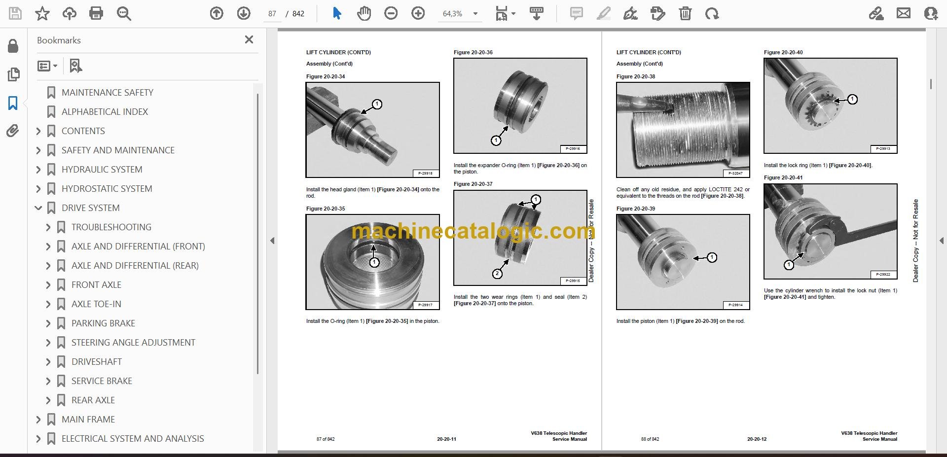
A VR638 VersaHANDLER is the farm and jobsite telehandler you use to stack bales, load manure, set trusses, and run forks or buckets where the skid steer just can't reach. When one of these starts leaking down, losing drive, or throwing electrical gremlins, this is when I pull the service manual off the shelf. Folks use it to get into the guts of the boom, axles, hydraulics, and wiring so the machine is ready again by Monday.

What this manual helps you do

  • Diagnose hydraulic problems in the boom, stabilizers, and steering, and pressure-test circuits with the right ports and test points
  • Check and adjust hydrostatic drive components when travel is weak, noisy, or jerky
  • Follow teardown and reassembly steps for cylinders, valves, and major mechanical parts like axles and driveline
  • Trace and troubleshoot electrical and wiring issues, from dead circuits to sensor and switch faults
  • Set and verify adjustments after repairs, like control linkages, safety interlocks, and limit switches

Who this is for

This manual is for anyone running or fixing a Bobcat VR638 VersaHANDLER TTC telehandler in the serial range 365111001 through 365111999, whether you're a small contractor, farm owner, or shop mechanic. If you just want basic controls, safety, and daily checks, you want the operator's handbook instead, not this.

FAQ

Q: Is this a searchable PDF, and can I read the wiring diagrams?

A: Yes, it's typically a searchable PDF, and the wiring diagrams are laid out so you can zoom in and follow circuits on a laptop or tablet.

Q: How do I know if it fits my exact machine?

A: Check your serial plate. If your VR638 serial number falls between 365111001 and 365111999, this is the right manual.

Q: Is this the right document if I'm doing my own repairs?

A: Yes, this is the workshop service manual, meant for actual repair work, not just operating or ordering parts.

If your VR638's serial number is in that range and you're planning to wrench on it yourself, this is the manual you want. If the serial doesn't match, don't buy it.

📘 Show Index

Table of Contents:

  • MAINTENANCE SAFETY
  • ALPHABETICAL INDEX
  • CONTENTS
    • FOREWORD
    • SAFETY INSTRUCTIONS
      • Fire Prevention
    • SERIAL NUMBER LOCATION
      • VersaHANDLER Serial Number
      • Engine Serial Number
      • Other Serial Numbers
    • DELIVERY REPORT
    • BOBCAT VersaHANDLER IDENTIFICATION
  • SAFETY AND MAINTENANCE
    • LIFTING AND BLOCKING THE VERSAHANDLER
      • Procedure
    • OPERATOR CAB/CANOPY
      • Emergency Exit
      • Cab Door
      • Cab Door Window
    • TRANSPORTING THE VersaHANDLER
      • Procedure
    • TOWING THE VersaHANDLER
      • Procedure
    • SERVICE SCHEDULE
    • AIR CLEANER SERVICE
      • Replacing Filter Element
    • ENGINE COOLING SYSTEM
      • Cleaning The Cooling System
      • Checking The Coolant Level
      • Replacing The Coolant
    • FUEL SYSTEM
      • Fuel Specifications
      • Filling The Fuel Tank
      • Fuel Filter
    • ENGINE LUBRICATION SYSTEM
      • Checking Engine Oil
      • Oil Chart
      • Replacing Oil And Filter
    • HYDRAULIC/HYDROSTATIC SYSTEM
      • Checking And Adding Fluid
      • Replacing Hydraulic/Hydrostatic Filter
      • Replacing Hydraulic Fluid
    • AXLES (FRONT AND REAR)
      • Checking Oil Level (Planetary Carrier)
      • Draining Oil (Planetary Carrier)
      • Checking Oil Level (Rear Differential)
      • Checking Oil Level (Front Differential)
      • Draining Oil (Front Differential)
    • LUBRICATION
      • Procedure
    • ATTACHMENT FRAME
      • Inspection And Maintenance
    • TIRE MAINTENANCE
      • Wheel Nuts
      • Tire Rotation
      • Tire Mounting
    • SPARK ARRESTOR MUFFLER
      • Cleaning
    • APPROVED BOOM STOP
      • Installing The Approved Boom Stop
      • Removing The Approved Boom Stop
    • ENGINE COVER
      • Opening And Closing The Engine Cover
    • LATERAL OPERATOR RESTRAINT SYSTEM (LORS™)
      • System Inspection
      • System Maintenance
    • CHAIN CHECKING AND ADJUSTING PROCEDURE
      • Checking/Adjustment Procedure
      • Extend/Retract Chain Wear Check
  • HYDRAULIC SYSTEM
    • HYDRAULIC/HYDROSTATIC SCHEMATICS
    • HYDRAULIC SYSTEM INFORMATION
      • Troubleshooting Chart
      • Tightening Procedures
    • LIFT CYLINDER
      • Removal And Installation
      • Parts Identification
      • Disassembly
      • Assembly
    • BUCKET POSITIONING CYLINDER
      • Removal And Installation
      • Removal And Installation (Cont’d)
      • Parts Identification
      • Disassembly
      • Disassembly (Cont'd)
      • Assembly
    • EXTENSION CYLINDER
      • Cylinder Group Removal And Installation
      • Parts Identification
    • TILT CYLINDER
      • Removal And Installation
      • Disassembly
    • STEERING CYLINDER (FRONT)
      • Removing The Steering Cylinder
      • Installing The Steering Cylinder
      • Disassembling The Steering Cylinder
      • Assembling The Steering Cylinder
    • STEERING CYLINDER (REAR)
      • Removing The Steering Cylinder
      • Installing The Steering Cylinder
      • Disassembling The Steering Cylinder
      • Assembling The Steering Cylinder
    • DRIVE BOX
      • Parts Identification
      • Disassembly
      • Assembly
      • Special Tools
    • MAIN RELIEF VALVE
      • Testing And Adjustment
      • Removal And Installation
    • QUICK TACH CYLINDER
      • Removal And Installation
      • Parts Identification
      • Disassembly
      • Assembly
    • FRAME LEVELING CYLINDER
      • Removal And Installation
      • Parts Identification
      • Disassembly
      • Assembly
    • STEERING MODE VALVE BLOCK
      • Removal And Installation
      • Parts Identification
      • Disassembly
      • Solenoid Testing
      • Assembly
    • BRAKE VALVE
      • Removal And Installation
      • Disassembly And Assembly
    • GEAR PUMP
      • Removal And Installation
      • Parts Identification
      • Disassembly And Assembly
    • FAN MOTOR
      • Removal And Installation
      • Parts Identification
      • Disassembly And Assembly
    • HYDRAULIC RESERVOIR
      • Removal And Installation
    • STEERING VALVE
      • Removal And Installation
      • Parts Identification
      • Disassembly
      • Inspection
      • Assembly
    • HYDRAULIC CONTROL VALVE
      • Troubleshooting Chart (Controllers)
      • Telescoping Valve Section Troubleshooting
      • Auxiliary Valve Section Troubleshooting
      • Troubleshooting Chart (Control Valve)
      • Removal And Installation
      • Parts Identification
      • Disassembly And Assembly
      • End Housing Disassembly And Assembly
      • Lifting Valve Section Disassembly And Assembly
      • Tilting Valve Section Disassembly And Assembly
      • Telescoping Valve Section Disassembly And Assembly
      • Auxiliary/Frame Leveling Valve Section Disassembly And Assembly
      • Inlet-Outlet Valve Section Disassembly And Assembly
    • PORT RELIEF VALVES
      • Adjustment Procedure
    • FLOW CONTROL VALVE
      • Removal And Installation
    • JOYSTICK
      • Removal And Installation
    • PARKING BRAKE
      • Pressure Switch Removal And Installation
      • Pressure Switch Disassembly And Assembly
      • Parking Brake Valve Removal And Installation
      • Parking Brake Valve Disassembly And Assembly
    • PRESSURE REDUCING VALVE
      • Testing
      • Removal And Installation
      • Disassembly And Assembly
    • ACCUMULATOR
      • Removal And Installation
    • TOW VALVE
      • Removal And Installation
      • Disassembly And Assembly
  • HYDROSTATIC SYSTEM
    • HYDROSTATIC SYSTEM INFORMATION
      • Troubleshooting Chart
      • Replenishing Valve Function
    • OIL COOLER
      • Description
    • HYDROSTATIC DRIVE MOTOR
      • Removal And Installation
      • Parts Identification
      • Disassembly
      • Inspection
      • Assembly
    • HYDROSTATIC PUMP
      • Removal And Installation
      • Parts Identification
      • Disassembly
      • Inspection
      • Assembly
    • CUSTOMER PACKING LIST
  • DRIVE SYSTEM
    • TROUBLESHOOTING
      • Chart
    • AXLE AND DIFFERENTIAL (FRONT)
      • General Information
      • Planetary Carrier Parts Identification
      • Planetary Carrier Disassembly
      • Planetary Carrier Disassembly (Cont’d)
      • Steering Knuckle And Drive Axle Parts Identification
      • Steering Knuckle Disassembly
      • Drive Axle Disassembly
      • Brake system Identification
      • Brake System Disassembly
      • Differential Parts Identification
      • Differential Disassembly
      • Bevel pinion Parts Identification
      • Bevel Pinion Disassembly
      • Bevel Pinion Disassembly (Cont’d)
      • Bevel Pinion Assembly
      • Setting Ring And Pinion Backlash
      • Brake System Assembly
      • Drive Axle Assembly
      • Steering Knuckle Assembly
      • Steering Knuckle Assembly (Cont’d)
      • Planetary Carrier Assembly
      • Special Tools
    • AXLE AND DIFFERENTIAL (REAR)
      • General Information
      • Planetary Carrier Parts Identification
      • Steering Knuckle And Drive Axle Parts Identification
      • Steering Knuckle Disassembly
      • Differential and Bevel Pinion Parts Identification
      • Differential Disassembly
      • Bevel Pinion Disassembly
      • Bevel Pinion Assembly
      • Bevel Pinion Assembly (Cont’d)
      • Differential Assembly
      • Steering Knuckle Assembly
      • Planetary Carrier Assembly
      • Special Tools
    • FRONT AXLE
      • Removal
      • Installation
    • AXLE TOE-IN
      • Adjustment
    • PARKING BRAKE
      • Releasing The Brake For Towing
      • Re-Activating The Brake
    • STEERING ANGLE ADJUSTMENT
      • Adjustment
    • DRIVESHAFT
      • Removal And Installation
    • SERVICE BRAKE
      • Description
      • Bleeding The Brake Circuit
    • REAR AXLE
      • Removal
      • Installation
  • MAIN FRAME
    • OPERATOR CAB
      • Removal And Installation
    • CANOPY
      • Removal And Installation
    • OPERATOR SEAT
      • Removal And Installation
    • FIXED BOOM
      • Removal
      • Installation
    • END BOOM
      • Removal
    • END BOOM
      • Installation
    • WEAR PADS (FRONT)
      • Removal
      • Installation
    • WEAR PADS (REAR)
      • Removal
    • WEAR PADS (REAR)
      • Installation
    • ENGINE COVER
      • Gas Cylinder Removal And Installation
      • Removal And Installation
    • AIR INTAKE COWLING
      • Removal And Installation
    • FUEL TANK
      • Removal And Installation
    • QUICK TACH
      • Removal And Installation
    • REAR WEIGHTS
      • Removal And Installation
    • FENDER
      • Removal And Installation
    • DASH COVER/STEERING COLUMN COVER
      • Removal And Installation
    • JOYSTICK PANEL
      • Removal And Installation
    • INTERMEDIATE BOOM
      • Removal
    • INTERMEDIATE BOOM
      • Installation
    • BOOM TRAY
      • Removal And Installation
    • CHAIN CHECKING AND ADJUSTING PROCEDURE
      • Checking/Adjustment Procedure
  • ELECTRICAL SYSTEM AND ANALYSIS
    • ELECTRICAL SCHEMATICS
    • ELECTRICAL SYSTEM INFORMATION
      • Troubleshooting Chart
      • Description
      • Fuses, Diodes & Relays
    • BATTERY
      • Removal And Installation
      • Servicing
      • Using A Booster Battery (Jump Starting)
    • ALTERNATOR
      • Removal And Installation
      • Adjusting The Alternator Belt
    • STARTER
      • Removal And Installation
      • Parts Identification
      • Disassembly
      • Inspection And Repair
      • Assembly
    • LATERAL OPERATOR RESTRAINT SYSTEM (LOR’S™)
      • Restraint Bar Removal And Installation
      • Strut Removal And Installation
      • Strut Disassembly And Assembly
      • Restraint Bar Bushing Removal And Installation
      • Restraint Bar Bumper Removal And Installation
    • LIGHTS
      • Rear Light Removal And Installation
      • Front Light Removal And Installation
    • TRAVEL/SIGNAL LEVER
      • Removal And Installation
    • INSTRUMENT PANEL
      • Removal And Installation
    • SWITCH PANEL
      • Removal And Installation
    • BRAKE LIGHT SWITCH
      • Removal And Installation
      • Adjustment
    • FRONT WIPER MOTOR
      • Removal And Installation
    • TOP WIPER MOTOR
      • Removal And Installation
    • REAR WIPER MOTOR
      • Removal And Installation
    • PEDAL ASSEMBLY
      • Removal And Installation
      • Disassembly And Assembly
    • INCHING SWITCH
      • Removal And Installation
      • Adjustment
    • SERVICE SOFTWARE
      • Connecting The Laptop Computer
      • Entering The Service Software
      • Monitor Screen
      • Warnings Screen
      • Calibrate Inch Pedal
      • Calibrate Creep Potentiometer
      • Program/Update Susmic Controller
    • FRAME LEVEL SPEED SWITCH
      • Description
      • Removal
      • Installation
  • ENGINE SERVICE
    • TROUBLESHOOTING
      • Chart
    • ENGINE SPEED CONTROL
      • Removal And Installation
    • MUFFLER
      • Removal And Installation
    • AIR CLEANER
      • Housing Removal And Installation
    • OIL COOLER/RADIATOR
      • Removal And Installation
      • Disassembly And Assembly
    • ENGINE AND ENGINE MOUNTS
      • Removal And Installation
    • ENGINE COMPONENTS AND TESTING
      • Fuel Injection Pump Removal
      • Fuel Injection Pump Installation
      • Fuel Injectors Removal And Installation
      • Checking The Fuel Lift Pump
      • Fuel Lift Pump Removal And Installation
      • Compression Checking
      • Glow Plugs Checking
      • Glow Plugs Removal And Installation
    • ENGINE TIMING
      • Procedure
    • ENGINE/HYDROSTAT ASSEMBLY
      • Removal And Installation
    • FLYWHEEL AND HOUSING
      • Removal And Installation
      • Ring Gear Removal
      • Ring Gear Installation
    • RECONDITIONING THE ENGINE
      • Turbo Charger Troubleshooting
      • Turbo Charger Description
      • Turbo Charger Removal And Installation
      • Exhaust Manifold Removal And Installation
      • Fuel Injector Cover Removal And Installation
      • Rocker Cover Removal And Installation
      • Cylinder Head Removal
      • Cylinder Head Inspection
      • Cylinder Head Installation
      • Rocker Shaft Disassembly And Assembly
      • Valve Removal
      • Valve Springs Checking
      • Valve Depth Checking
      • Valve Guides Checking
      • Valve Guide Removal
      • Valve Guide Installation
      • Valves Checking
      • Cutting A Valve Seat
      • Valve Seat Assembly
      • Changing Valve Springs (With Cylinder Head Installed)
      • Valve Clearance Adjustment
      • Timing Case And Drive Assembly Description
      • Timing Cover Removal
      • Timing Cover Installation
      • Crankshaft Pulley Removal And Installation
      • Front Oil Seal Removal And Installation
      • Timing Case And Gear Removal
      • Timing Case And Gear Installation
      • Camshaft And Tappets Removal
      • Camshaft And Tappets Installation
      • Pistons And Connecting Rods Description
      • Pistons And Connecting Rods Removal
      • Pistons And Connecting Rods Disassembly
      • Piston Ring End Gap
      • Piston Ring Groove Clearance
      • Connecting Rod Inspection
      • Connecting Rod Bushing Replacement
      • Piston And Connecting Rod Assembly
      • Checking Piston Height
      • Crankshaft And Bearings Description
      • Crankshaft And Bearings Removal
      • Inspection Of Crankshaft And Bearings
      • Crankshaft And Bearings Installation
      • Rear Oil Seal Removal
      • Rear Oil Seal Housing Positioning
      • Rear Oil Seal Installation
      • Checking Crankshaft End Play
      • Cooling System Description
      • Thermostat Removal and Installation
      • Thermostat Testing
      • Lubricating Oil Cooler Removal And Installation
      • Water Pump Removal
      • Water Pump Installation
      • Engine Lubrication System Description
      • Oil Filter Adapter Removal And Installation
      • Oil Pan Removal And Installation
      • Oil Screen And Pick-up Tube
      • Oil Pump Removal
      • Oil Pump Installation
      • Oil Pump Disassembly And Assembly
      • Oil Pressure Relief Valve Disassembly And Assembly
      • Engine Block Description
      • Engine Block Disassembly And Assembly
      • Piston Cooling Jet Removal
      • Piston Cooling Jet Installation
      • Piston Cooling Jet Alignment
      • Inspection
      • Cylinder Liner Inspection
      • Cylinder Liner Removal
      • Cylinder Liner Installation
  • HEATING, VENTILATION, AIR CONDITIONING
    • AIR CONDITIONING SYSTEM FLOW
      • Principals
      • Chart
    • COMPONENTS
      • Identification
    • SAFETY
      • Safety Equipment
    • REGULAR MAINTENANCE
      • Filter Element Removal And Installation
      • Compressor Drive Belt Inspection
      • Cleaning The Condenser
    • BASIC TROUBLESHOOTING
      • Poor A/C Performance
      • Compressor Drive Belt Inspection
      • Checking The Electrical System
    • GENERAL AIR CONDITIONING SERVICE GUIDELINES
      • Compressor Oil
      • Compressor Oil Check
      • Component Replacement And Refrigeration Leaks
    • SYSTEM TROUBLESHOOTING CHART
    • TEMPERATURE/PRESSURE
      • Chart
    • AIR CONDITIONING SERVICE
      • Chart
    • SYSTEM CHARGING AND RECLAMATION
      • Reclamation Procedure
      • Charging Procedure With A Manifold Gauge Set
      • Charging Procedure
    • COMPRESSOR
      • Removal And Installation
      • Compressor Clutch Disassembly And Assembly
    • CONDENSER
      • Removal And Installation
    • RECEIVER/DRIER
      • Removal And Installation
    • PRESSURE SWITCH
      • Removal And Installation
    • EVAPORATOR/BLOWER UNIT
      • Removal And Installation
    • EXPANSION VALVE
      • Removal And Installation
    • HEATER ASSEMBLY
      • Removal And Installation
      • Fan Removal And Installation
      • Core Removal And Installation
  • SPECIFICATIONS
    • VersaHANDLER SPECIFICATIONS
      • Dimensional Specifications
      • Performance Specifications
      • Engine
      • Controls
      • Drive System
      • Tires
      • Capacities
      • Hydraulic System
      • Electrical System
      • Instrument Panel
    • ENGINE SPECIFICATIONS
      • General
      • Cylinder Head
      • Valve Guides
      • Exhaust Valves
      • Intake Valves
      • Valve Springs
      • Rocker Shaft, Rockers And Bushings
      • Pistons And Piston Rings
      • Connecting Rods And Bearings
      • Crankshaft
      • Crankshaft Re-Grind Data
      • Main Bearings
      • Thrust Washers
      • Camshaft And Thrust Washer
      • Cylinder Block
      • Cylinder Liners
      • Fuel Injection Pump
      • Fuel Injectors
      • Fuel Lift Pump
      • Timing Case And Timing Gears
      • Oil Pump, Gear And Relief Valve
      • Turbocharger
      • Flywheel
      • Water Pump And Thermostat
      • Engine Torque Component
    • MACHINE TORQUE SPECIFICATIONS
      • Axle
      • Boom
      • Drive Box
      • Drive Motor
      • Engine
      • Hydraulic Pump
    • TORQUE SPECIFICATIONS FOR BOLTS
      • Torque for General SAE Bolts
      • Torque For General Metric Bolts
    • HYDRAULIC CONNECTION SPECIFICATIONS
      • O-ring Face Seal Connection
      • Straight Thread O-ring Fitting
      • Tubelines And Hoses
      • Port Seal Fitting
    • HYDRAULIC/HYDROSTATIC FLUID SPECIFICATIONS
      • Specifications
    • CONVERSIONS
      • Decimal And Millimeter Equivalents
      • U.S. To Metric Conversion
  • SMR
    • V638-1

Bobcat Software

Bobcat PDF Manuals

Related Manuals

0
    0
    Your Cart
    Your cart is emptyReturn to Shop