On a real job, a 442 is digging footings, trenching utilities, loading trucks, and sitting on slopes where a blown hose or bad sensor can stop your day cold. The person who reaches for this manual is the one who actually has to fix that, not just call the dealer. Around my shop, I pull the service manual when I need teardown steps, test ports, or specs that I don't trust my memory on. If you're trying to keep an older 442 earning instead of bleeding cash at the dealer, this is the book you reach for.
What this manual helps you do
- Trace hydraulic circuits so you can find weak functions, slow boom, or swing issues on the 442.
- Check and set hydraulic and hydrostatic test points when you're chasing low power or overheating.
- Follow step-by-step removal and install procedures for pumps, final drives, swing motors, and cylinders.
- Diagnose electrical problems using wiring diagrams, connector callouts, and sensor/solenoid test info.
- Rebuild major components like control valves or engine assemblies with correct sequences and reference data.
Who this is for
This is for anyone working on a Bobcat 442 excavator in the serial range ADBR11001 through ADBR99999: small contractors, owner-operators, shop mechanics, and rental fleets. If you just need operating instructions or basic maintenance intervals, you want the operator's handbook, not this service manual.
FAQ
Q: Is this a searchable PDF, and can you actually read the wiring diagrams?
A: Yes, it's a PDF and you can search text. Wiring diagrams are scan-quality you can zoom in on to read pin numbers and wire colors.
Q: How do I know if it fits my exact 442?
A: Check your serial plate. If your 442 serial number falls between ADBR11001 and ADBR99999, this is the right manual.
Q: Is this what I need for real repairs, not just oil changes?
A: Yes. This is the workshop-level service manual, meant for diagnostics, teardown, and repair, not routine greasing and checks.
Bottom line: If you own or wrench on a 442 in that serial range and you're doing your own repairs, this is the right manual. If your machine is outside that range, don't buy it.
📘 Show Index
Table of Contents:
- MAINTENANCE SAFETY
- ALPHABETICAL INDEX
- CONTENTS
- FOREWORD
- SAFETY INSTRUCTIONS
- FIRE PREVENTION
- Maintenance
- Operation
- Electrical
- Hydraulic System
- Fueling
- Starting
- Spark Arrestor Exhaust System
- Welding And Grinding
- Fire Extinguishers
- SERIAL NUMBER LOCATIONS
- Excavator Serial Number
- Engine Serial Number
- DELIVERY REPORT
- SAFETY AND MAINTENANCE
- LIFTING AND BLOCKING THE EXCAVATOR
- LIFTING THE EXCAVATOR
- OPERATOR CAB
- Description
- Entering And Exiting The Excavator
- Raising And Lowering The Left Console
- Emergency Exit
- TRANSPORTING THE EXCAVATOR
- REAR COVER
- Opening And Closing The Rear Cover
- RIGHT SIDE COVER
- Opening And Closing The Right Side Cover
- SERVICE SCHEDULE
- AIR CLEANER
- Daily Check
- Replacing The Filters
- FRESH AIR FILTER
- COOLING SYSTEM
- Cleaning The Cooling System
- Checking Coolant Level
- Replacing The Coolant
- FUEL SYSTEM
- Fuel Specifications
- Filling The Fuel Tank
- Pre-Filter Removal And Installation
- Fuel Filter Removal And Installation
- Draining The Fuel Tank
- ENGINE LUBRICATION SYSTEM
- Checking Engine Oil
- Oil Chart
- Replacing Oil And Filter
- HYDRAULIC SYSTEM
- Checking And Adding Hydraulic Oil
- Replacing The Hydraulic Oil
- Hydraulic Filter Removal
- Hydraulic Filter Installation
- Diagnostic Couplers
- LUBRICATION OF THE EXCAVATOR
- TRAVEL MOTOR
- Checking Oil Level
- Draining The Travel Motor
- ALTERNATOR BELT
- FAN/FUEL PUMP BELT
- AIR CONDITIONING COMPRESSOR BELT
- CAB TILT PROCEDURE
- Installing The Cab Tilt Hinges
- Tilting The Cab
- HYDRAULIC SYSTEM
- HYDRAULIC / HYDROSTATIC SCHEMATICS
- HYDRAULIC SYSTEM INFORMATION
- Troubleshooting Chart
- Description
- BOOM CYLINDER
- Testing
- Removal And Installation
- Parts Identification
- Disassembly
- Assembly
- ARM CYLINDER
- Testing
- Removal And Installation
- Parts Identification
- Disassembly
- Assembly
- BOOM OFFSET CYLINDER
- BOOM OFFSET CYLINDER
- Removal And Installation
- Parts Identification
- Disassembly
- Assembly
- BUCKET CYLINDER
- Testing
- Removal And Installation
- Parts Identification
- Disassembly
- Assembly
- BLADE CYLINDER
- Testing
- Removal And Installation
- Parts Identification
- Disassembly
- Assembly
- RELIEF VALVES
- Description
- Testing The Three Spool Control Valve Main Relief Valve
- Adjusting The Three Spool Control Valve Main Relief Valve
- PORT RELIEF VALVES
- PRESSURE REDUCING VALVE
- Description
- Testing
- Adjustment
- DUMP VALVE
- Description
- Testing
- Adjustment
- Removal And Installation
- Parts Identification
- Disassembly And Assembly
- SIX SPOOL HYDRAULIC CONTROL VALVE
- Removal And Installation
- Control Valve Identification
- Disassembly And Assembly
- Left Travel And Right Travel Valve Section Disassembly And Assembly
- Boom, Arm, Bucket And Auxiliary Valve Section Disassembly And Assembly
- Inlet Valve Section Disassembly And Assembly
- THREE SPOOL HYDRAULIC CONTROL VALVE
- Removal And Installation
- Parts Identification
- Disassembly And Assembly
- Boom Offset And Blade Valve Section Disassembly And Assembly
- Inlet/Upperstructure Swing Valve Section Disassembly And Assembly
- HYDRAULIC PISTON PUMP
- Hydraulic Pump Work Sheet
- Testing Information
- Pump Testing
- Load Sense Relief Valve Adjustment
- Removal And Installation
- Coupler Removal And Installation
- Torque Limiter Valve Parts Identification
- Torque Limiter Valve Removal and Installation
- Torque Limiter Valve Disassembly
- Torque Limiter Valve Assembly
- Initial Torque Limiter Valve Setting
- Pump Control Parts Identification
- Pump Control Removal And Installation
- Pump Control Disassembly And Assembly
- Parts Identification
- Disassembly
- Assembly
- HYDRAULIC GEAR PUMP
- Removal And Installation
- Parts Identification
- Disassembly
- Assembly
- ACCUMULATOR
- Description
- Removal And Installation
- TRAVEL MOTOR
- Removal And Installation
- Parts Identification
- Disassembly
- Assembly
- SWIVEL JOINT
- Removal And Installation
- Parts Identification
- Disassembly And Assembly
- SWING MOTOR
- Removal And Installation
- Parts Identification
- Disassembly
- Assembly
- SWING MOTOR DRIVE CARRIER
- Removal And Installation
- Parts Identification
- Disassembly
- Assembly
- SWING BRAKE VALVE
- Removal And Installation
- Parts Identification
- Disassembly And Assembly
- SWING BRAKE RELEASE VALVE
- SWING BRAKE RELEASE VALVE (CONT’D)
- Parts Identification
- Disassembly And Assembly
- JOYSTICK CONTROL PATTERN SELECTOR VALVE
- Removal And Installation
- Parts Identification
- Disassembly And Assembly
- JOYSTICK LOCKOUT/TWO SPEED VALVE
- Removal And Installation
- Parts Identification
- Disassembly And Assembly
- RIGHT CONTROL LEVER (JOYSTICK)
- Testing
- Handle Removal And Installation
- Removal And Installation
- Parts Identification
- Disassembly And Assembly
- LEFT CONTROL LEVER (JOYSTICK)
- Testing
- Handle Removal And Installation
- Removal And Installation
- Parts Identification
- Disassembly and Assembly
- TRAVEL LEVER/FOOT PEDAL VALVE
- Left Travel Lever/Foot Pedal Valve Removal And Installation
- Right Travel Lever/Foot Pedal Valve Removal And Installation
- Parts Identification
- Disassembly And Assembly
- HYDRAULIC FILTER MOUNT
- HYDRAULIC RESERVOIR
- OIL COOLER
- SECONDARY FRONT AUXILIARY VALVE
- Removal And Installation
- Parts Identification
- Disassembly And Assembly
- AUXILIARY HYDRAULIC FLOW CONTROL/ HYDRAULIC BREAKER APPLICATION VALVE
- AUXILIARY HYDRAULIC FLOW CONTROL/HYDRAULIC BREAKER APPLICATION VALVE (CONT’D)
- Parts Identification
- Disassembly And Assembly
- BLADE VALVE
- Removal And Installation
- Parts Identification
- Disassembly And Assembly
- BLADE FLOAT VALVE
- Removal And Installation
- Parts Identification
- Disassembly And Assembly
- BOOM OFFSET VALVE
- Removal And Installation
- Parts Identification
- Disassembly And Assembly
- BOOM LOAD HOLDING VALVE
- Removal And Installation
- Parts Identification
- Disassembly
- Assembly
- OIL TEMPERATURE REGULATOR
- Description
- Removal And Installation
- AUXILIARY HYDRAULICS SELECTOR VALVE
- HYDRAULIC PISTON PUMP DRIVE COUPLER
- UNDERCARRIAGE
- BLADE
- TRACKS
- Track Lug Height
- Rubber Track Clearance
- Steel Track Clearance
- Track Adjustment
- Rubber Track Removal And Installation
- TRACK FRAME
- Disassembly And Assembly
- Drive Sprocket Removal And Installation
- TRACK IDLER
- Parts Identification
- Disassembly
- Assembly
- UPPER TRACK ROLLER
- Parts Identification
- Disassembly
- Assembly
- LOWER TRACK ROLLER
- Parts Identification
- Disassembly
- Assembly
- GREASE CYLINDER
- Parts Identification
- Disassembly
- Assembly
- TRACK DAMAGE IDENTIFICATION
- Cutting Of Steel Cords
- Abrasion Of Embedded Metals
- Separation Of Embedded Metals
- Separation Of Embedded Metals Due To Corrosion
- Cuts On The Lug Side Rubber
- Cracks On The Lug Side Rubber Due To Fatigue
- Lug Abrasion
- Cracks And Cuts On The Lug Side Rubber
- Abrasion Of The Track Roller Side
- Cuts On The Edges Of Track Roller Side
- UPPERSTRUCTURE & SWING SECTION
- UPPERSTRUCTURE
- Removal And Installation
- Swing Bearing Removal And Installation
- CAB
- Removal And Installation
- Door Removal And Installation
- Front Window Removal And Installation
- Front Window Gas Strut Removal And Installation
- Front Window Pivot Frame Removal And Installation
- Lower Front Widow Removal And Installation
- Door, Left Side, Right Side And Rear Window Removal
- Door, Left Side, Right Side And Rear Window Installation
- Cab Visor Removal And Installation
- Top Window Removal And Installation
- SEAT AND SEAT MOUNT
- RIGHT CONSOLE
- LEFT CONSOLE
- Removal And Installation
- Disassembly And Assembly
- Console Lockout Switch Removal And Installation
- ENGINE SPEED CONTROL
- Removal And Installation
- Disassembly And Assembly
- CONTROL LEVERS
- FUEL TANK
- HORN
- SWING FRAME
- Removal And Installation
- Bushing Removal And Installation
- FLOOR MAT
- BOOM
- Removal And Installation
- Bushing Removal And Installation
- ARM
- Removal And Installation
- Bushing Removal And Installation
- BUCKET
- REAR COVER
- RIGHT SIDE COVER
- COUNTERWEIGHT
- ELECTRICAL SYSTEM AND ANALYSIS
- ELECTRICAL SCHEMATICS
- ELECTRICAL SYSTEM INFORMATION
- Troubleshooting Chart
- Description
- Fuse And Relay Location
- BATTERY
- Servicing
- Removal And Installation
- Using A Booster Battery (Jump Starting)
- ALTERNATOR
- Removal And Installation
- Parts Identification
- Alternator Identification
- Charging System Check
- Rectifier Continuity (Diode) Test
- Disassembly
- Stator Continuity Test
- Stator Ground Test
- Rotor Continuity Test
- Rotor Ground Test
- Capacitor Continuity Test
- Assembly
- STARTER
- Removal And Installation
- Parts Identification
- Disassembly
- Inspection And Repair
- Assembly
- FRONT CAB LIGHT
- Removal And Installation
- Disassembly And Assembly
- TWO SPEED SWITCH
- FUEL LEVEL SENDER
- WIPER MOTOR
- BATTERY DISCONNECT SWITCH
- INSTRUMENT PANEL
- Removal And Installation
- E-Prom Information
- OIL TEMPERATURE COMPONENTS
- Sensor Testing
- Gauge Testing
- ENGINE SERVICE
- TROUBLESHOOTING
- MUFFLER
- AIR CLEANER
- RADIATOR/OIL COOLER
- ENGINE COMPONENTS AND TESTING
- Engine Compression Checking
- Checking The Manifold Heater
- Manifold Heater Removal And Installation
- Fuel Shutoff Solenoid Checking
- Fuel Shutoff Solenoid Removal And Installation
- Fuel Injection Pump Removal
- Fuel Injection Pump Timing
- Fuel Injection Pump Installation
- Fuel Injector Removal And Installation
- Fuel Injector, Checking
- Fuel Injector Disassembly
- Fuel Injector Assembly
- Timing Belt Inspection
- Timing Belt Removal
- Timing Belt Installation
- Valve Clearance Adjustment
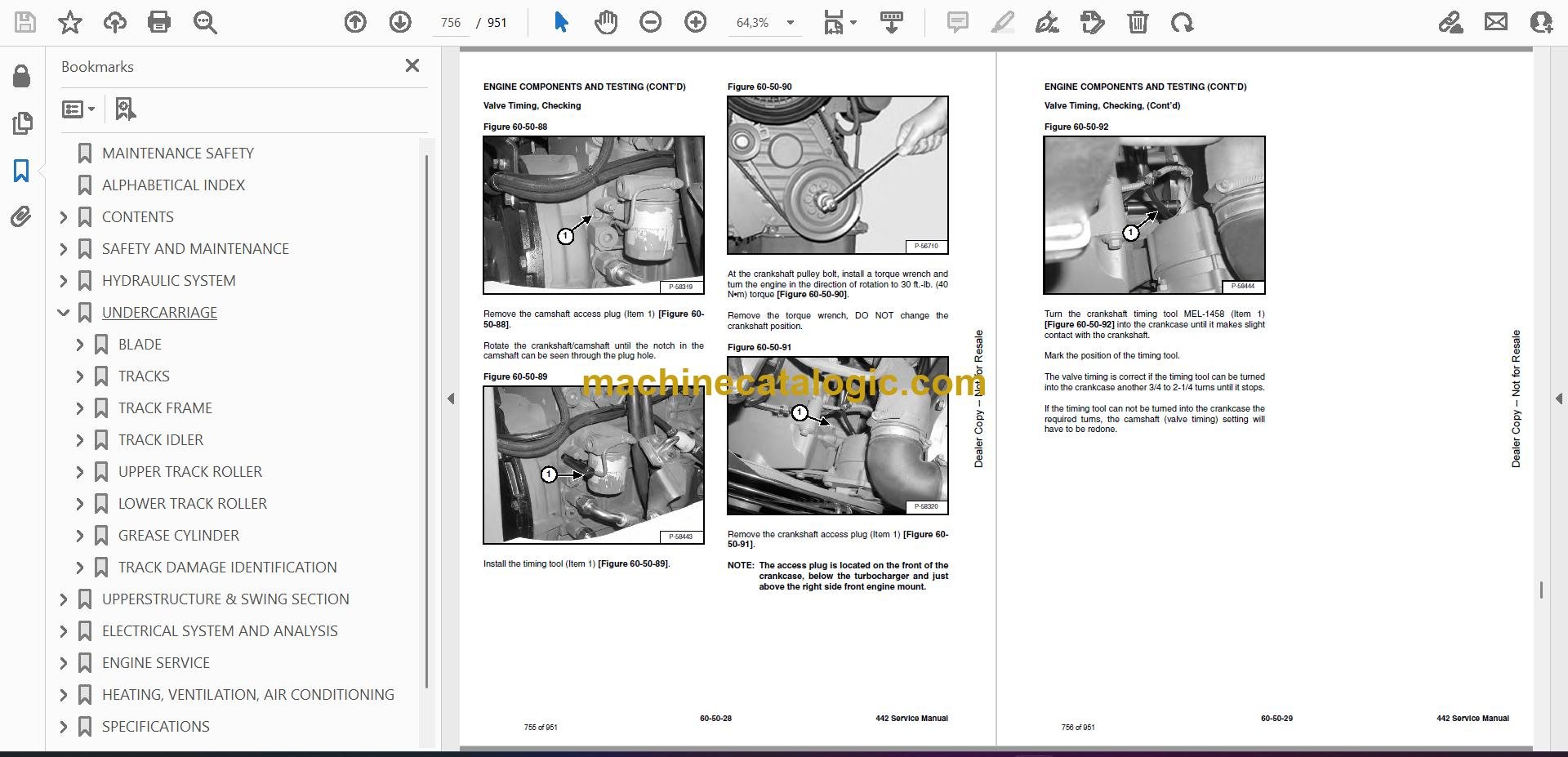
- Valve Timing, Checking
- Aneroid Device
- ENGINE
- FLYWHEEL
- Removal And Installation
- Flywheel Ring Gear
- RECONDITIONING THE ENGINE
- Deutz Engine Tools Identification Chart
- Disassembly
- Assembly
- Cylinder, Checking
- Camshaft Bearing, Checking
- Camshaft Bearing, Removal And Installation
- Control Rod Guide Bushing Removal
- Control Rod Guide Bushing Installation
- Rear Cover Seal Removal And Installation
- Crankshaft, Checking
- Connecting Rod, Checking
- Piston, Checking
- Piston Pin, Checking
- Piston Rings Installation
- Piston Installation On The Connecting Rod
- Cylinder Head Disassembly
- Valves, Checking
- Valve Clearance Adjustment
- Cylinder Head Assembly
- Rocker Arm And Bracket, Checking
- Front Cover Disassembly
- Front Cover Assembly
- Turbo Charger Removal and Installation
- Crankshaft Gear Mounting Bolt Torque Procedure
- HEATING, VENTILATION, AIR CONDITIONING
- EVAPORATOR UNIT
- Removal And Installation
- Disassembly And Assembly
- Evaporator Removal And Installation
- Fan Removal And Installation
- Switch Removal And Installation
- HEATER UNIT
- Removal And Installation
- Disassembly And Assembly
- HEATER FAN
- Removal And Installation
- Resistor Removal And Installation
- AIR CONDITIONING FAN
- Removal And Installation
- Switch Removal And Installation
- HEATER VALVE
- AIR CONDITIONING SYSTEM FLOW
- COMPONENTS
- SAFETY
- REGULAR MAINTENANCE
- Heater Air Filter
- Air Conditioning Compressor Belt
- Cleaning The Condenser
- BASIC TROUBLESHOOTING
- Poor A/C Performance
- Compressor Drive Belt Inspection
- Cleaning The Heater Coil
- Cleaning The A/C Evaporator Coil
- Checking The Electrical System
- Engine Coolant Bypassing The Heater Valve
- GENERAL AIR CONDITIONING SERVICE GUIDELINES
- Compressor Oil
- Compressor Oil Check
- Component Replacement And Refrigeration Leaks
- SYSTEM TROUBLESHOOTING CHART
- Blower Motor
- Gauge Pressure Related Troubleshooting
- TEMPERATURE/PRESSURE
- AIR CONDITIONING SERVICE
- SYSTEM CHARGING AND RECLAMATION
- COMPRESSOR
- Removal And Installation
- Compressor Clutch Disassembly And Assembly
- CONDENSOR
- RECEIVER/DRYER
- PRESSURE SWITCH
- HEATER COIL
- THERMOSTAT
- SPECIFICATIONS
- HYDRAULIC EXCAVATOR SPECIFICATIONS
- Excavator Machine Dimensions
- Performance
- Controls
- Engine
- Electrical
- Hydraulic System
- Hydraulic Cycle Times
- Swing System
- Hydraulic Cylinders
- Drive System
- Brake
- Undercarriage
- Track
- Capacities
- ENGINE SPECIFICATIONS
- General
- Fuel System
- Valve, Valve Guide And Seat Insert
- Piston And Rings
- Connecting Rod
- Cylinder Head And Block
- Crankshaft And Main Bearings
- Camshaft And Bearings
- Oil Pump
- Governor
- ENGINE BOLT TORQUE
- EXCAVATOR BOLT TORQUE
- TORQUE SPECIFICATIONS FOR BOLTS
- Torque For General SAE Bolts
- Torque For General Metric Bolts
- HYDRAULIC FLUID SPECIFICATIONS
- FUEL, COOLANT AND LUBRICANTS
- CONVERSIONS
- Decimal And Millimeter Equivalents
- U.S. To Metric Conversion
- SERVICE MANUAL REVISION
Bobcat Software
Bobcat PDF Manuals


