$ 0
0
$ 0
0

Bobcat 553 Loader Service Manual (SN 528011001-528099999)

Format: PDF (Printable Document)

File Language: English

File Pages: 411

File Size: 13.13 MB (Speed Download Link)

Brand: Bobcat

Model: 553 Loader

Book No: 6903125

Serial No: SN 528011001-528099999

Type of Document: Service Manual

Categories: ,

$ 45

Share:

Bobcat 553 Loader Service Manual (SN 528011001-528099999)

The Bobcat 553 is a small skid-steer loader that lives on tight jobsites, rental yards, and farm lots where it does light dirt work, snow, and material handling. The service manual is what the mechanic or hands-on owner grabs when the machine is down and they need real repair info, not just how to run the controls. In my shop, this is what I'd use when a 553 comes off rent with a drive issue, a hydraulic leak, or an electrical fault and I need it turned around fast. If your 553 falls in serial range 528011001 to 528099999, this is aimed right at your machine.

What this manual helps you do

  • Diagnose hydraulic and hydrostatic problems, then check pressures and track down internal leaks
  • Trace electrical faults using wiring diagrams, then test and replace switches, relays, and sensors
  • Follow step-by-step teardown and reassembly for the engine, drive motors, and major components
  • Adjust linkages, controls, chains, and brakes to factory specs after repairs or wear checks
  • Replace and reseal cylinders, valves, and pumps with correct sequences and torque references

Who this is for

This is for a shop mechanic, field tech, rental fleet, or owner-operator who is doing their own repairs on a Bobcat 553 in that serial range. If you only need basic controls, safety, and daily checks, you want the operator's handbook instead, not this manual.

FAQ

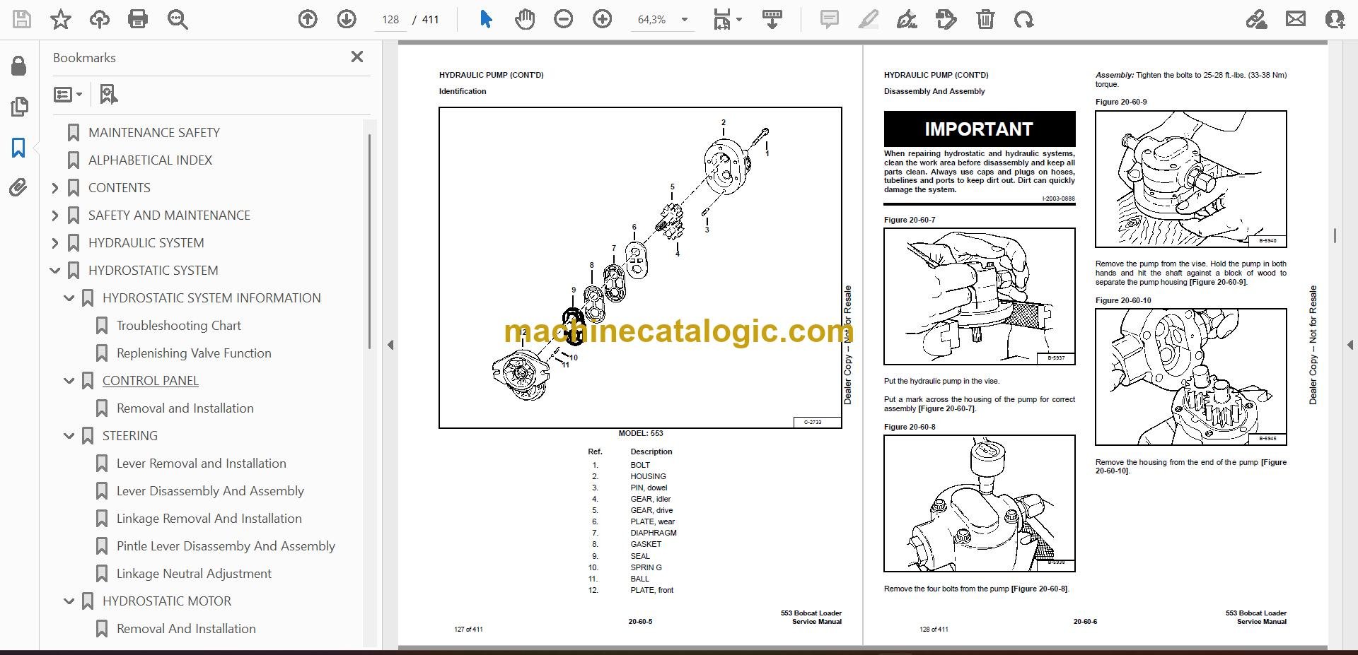
Q: Is this a searchable PDF and are the wiring diagrams readable?

A: Yes, these manuals are typically supplied as searchable PDFs, and the wiring diagrams are clear enough to zoom in and read pin labels.

Q: How do I know if it covers my exact 553?

A: Check your loader's serial plate. If it falls between 528011001 and 528099999, this is the correct service manual.

Q: Is this what I need for real repairs, not just maintenance?

A: Yes, this is the workshop-level service manual used for diagnostics, teardown, and rebuild work, not just routine service.

Bottom line: If your 553's serial number is in that range and you're doing your own repairs, this is the right manual. If your serial is outside that range, skip it.

📘 Show Index

Table of Contents:

  • MAINTENANCE SAFETY
  • ALPHABETICAL INDEX
  • CONTENTS
    • SAFETY INSTRUCTIONS
      • Fire Prevention
    • SERIAL NUMBER LOCATION
      • Loader Serial Number
      • Engine Serial Number
    • DELIVERY REPORT
    • BOBCAT LOADER IDENTIFICATION
  • SAFETY AND MAINTENANCE
    • LIFTING AND BLOCKING THE LOADER
      • Procedure
    • LIFT ARM SUPPORT DEVICE
      • Installing Lift Arm Support Device
      • Removing Lift Arm Support Device
    • OPERATOR CAB
      • Description
      • Raising The Operator Cab
      • Lowering The Operator Cab
      • Emergency Exit
    • TRANSPORTING THE BOBCAT LOADER
      • Procedure
      • Stopping The Bobcat Loader
    • TOWING THE LOADER
      • Procedure
    • REMOTE START
      • Procedure
    • SERVICE SCHEDULE
      • Chart
    • AIR CLEANER SERVICE
      • Replacing Filter Element
    • ENGINE COOLING SYSTEM
      • Cleaning The Cooling System
      • Checking The Coolant Level
      • Replacing The Coolant
    • FUEL SYSTEM
      • Fuel Specifications
      • Filling The Fuel Tank
      • Fuel Filter
      • Removing Air From The Fuel System
    • ENGINE LUBRICATION SYSTEM
      • Checking Engine Oil
      • Oil Chart
      • Replacing Oil And Filter
    • HYDRAULIC/HYDROSTATIC SYSTEM
      • Description
      • Checking And Adding Fluid
      • Replacing The Hydraulic/Hydrostatic Filter
      • Replacing Hydraulic Fluid
    • FINAL DRIVE TRANSMISSION (CHAINCASE)
      • Checking And Adding Oil
    • AUXILIARY CONTROL LOCKBOLT
      • Removal
    • BOB-TACH
      • Inspection And Maintenance
    • LUBRICATION OF THE BOBCAT LOADER
      • Procedure
    • TIRE MAINTENANCE
      • Wheel Nuts
      • Rotating
      • Mounting
    • SPARK ARRESTOR MUFFLER
      • Cleaning Procedure
    • PIVOT PINS
      • Procedure
    • SEAT BAR RESTRAINT SYSTEM
      • Description
      • Seat Bar Inspection
      • Seat Bar Maintenance
    • RUBBER COUPLER LUBRICATION
      • Procedure
  • HYDRAULIC SYSTEM
    • HYDRAULIC/HYDROSTATIC SCHEMATICS
    • HYDRAULIC SYSTEM INFORMATION
      • Tighten Procedures
      • Troubleshooting Chart
    • CYLINDER (LIFT)
      • Checking
      • Removal And Installation
      • Identification
      • Disassembly And Assembly
    • CYLINDER (TILT)
      • Checking
      • Removal And Installation
      • Identification
      • Disassembly And Assembly
    • MAIN RELIEF VALVE
      • Checking The Main Relief Valve Without Auxiliaries
      • Checking The Main Relief Valve With Auxiliaries
      • Removal and Installation
    • HYDRAULIC CONTROL VALVE
      • Removal And Installation
      • Identification Chart
      • Disassembly And Assembly
      • Load Check Valve
      • Main Releif Valve
      • Anti-Cavitation Check Valve
      • Port Relief Valve
      • Rubber Boot (Lift)
      • Rubber Boot (Tilt)
      • Rubber Boot (Aux.)
      • Lift Spool Detent
      • Tilt Centering Spring
      • Auxiliary Spool Detent
      • One Way Restrictors
      • Inspection
      • Spool Seal Installation
    • LIFT ARM BY-PASS CONTROL VALVE
      • Inspecting
      • Removal and Installation
      • Disassembly and Assembly
    • TILT LOCK VALVE
      • Removal And Installation
      • Disassembly and Assembly
    • HYDRAULIC PUMP
      • Check The Output Of The Hydraulic Pump
      • Removal And Installation
      • Identification
      • Disassembly And Assembly
      • Inspection
    • HYDRAULIC FILTER HOUSING
      • Removal and Installation
    • HYDRAULIC FLUID RESERVOIR
      • Removal and Installation
  • HYDROSTATIC SYSTEM
    • HYDROSTATIC SYSTEM INFORMATION
      • Troubleshooting Chart
      • Replenishing Valve Function
    • CONTROL PANEL
      • Removal and Installation
    • STEERING
      • Lever Removal and Installation
      • Lever Disassembly And Assembly
      • Linkage Removal And Installation
      • Pintle Lever Disassemby And Assembly
      • Linkage Neutral Adjustment
    • HYDROSTATIC MOTOR
      • Removal And Installation
      • Parts Identification
      • Disassembly And Assembly
      • Inspection
      • Timing The Hydrostatic Motor
    • PORT BLOCK
      • Removal And Installation
      • Oil Cooler By-Pass Valve
      • Hydraulic Oil Temperature Switch
      • Charge Pressure By-Pass Valve
    • HYDROSTATIC PUMP
      • Checking Charge Pressure
      • Removal And Installation
      • Drive Coupler Removal And Installation
      • Parts Identification
      • Disassembly And Assembly
      • Inspection
    • OIL COOLER
      • Removal and Installation
  • DRIVE SYSTEM
    • PARKING BRAKE
      • Disk Removal And Installation
      • Traction Lock Guides Removal And Installation
    • DRIVE COMPONENTS
      • Axle Seal Removal And Installation
      • Axle, Bearing, And Sprocket Removal And Installation
      • Chain Removal And Installation
    • CHAINCASE
      • Removing Oil From The Chaincase
      • Front Cover Removal And Installation
      • Rear Cover Removal And Installation
  • MAIN FRAME
    • SEAT BAR
      • Removal And Installation
      • Assembling Components
      • Compression Spring Disassembly And Assembly
    • OPERATOR CAB
      • Gas Cylinder Removal And Installation
      • Gas Cylinder Disassembly And Assembly
      • Removal And Installation
    • OPERATOR SEAT
      • Removal And Installation
      • Seat Belt Removal And Installation
    • BOB-TACH
      • Removal And Installation
      • Bob-Tach Lever And Wedge
    • LIFT ARM
      • Removal And Installation
    • REAR GRILL
      • Removal And Installation
    • REAR DOOR
      • Removal And Installation
      • Striker Removal and Installation
      • Striker Disassembly and Assembly
      • Adjusting The Striker
      • Latch Removal and Installation
    • FUEL TANK
      • Removal And Installation
      • Fuel Level Sender
    • CONTROL PEDALS
      • Removal And Installation
      • Pedal Adjustment
      • Pedal Interlock Linkage Removal And Installation
      • Pedal Interlock Linkage Adjustment
      • Crossbar Linkage Removal And Installation
  • ELECTRICAL SYSTEM
    • ELECTRICAL SCHEMATICS
    • ELECTRICAL SYSTEM INFORMATION
      • Troubleshooting
      • Description
      • Fuse Location
      • Relay Switches Location
    • BATTERY
      • Removal And Installation
      • Using A Booster Battery (Jump Starting)
    • ALTERNATOR
      • Removal And Installation
      • Adjusting The Alternator Belt
      • Description
      • Tests
      • Alternator Output Test
      • Full Field Test
      • Alternator Regulator Test
      • Alternator Regulator Test Using Voltmeter
      • Parts Identification
      • Pulley Removal And Installation
      • Disassembly And Assembly
      • Rotor Continuity Test
      • Stator Continuity Test
      • Rectifier Continuity (Diode) Test
      • Brush Length
    • STARTER
      • Removal And Installation
      • Checking The Starter In The Loader
      • Parts Identification
      • Disassembly
      • Inspection And Repair
      • No Load Test
      • Assembly
    • INSTRUMENT PANEL
      • Removal And Installation
    • LIGHTS
      • Front Removal And Installation
    • BICS™ SYSTEM CONTROLLER
      • Trouble Shooting Guide
      • Removal And Installation
    • BICS™ SYSTEM (WITH PRESS TO OPERATE BUTTON)
      • Inspecting The BICS™ Controller (Engine STOPPED – Key ON)
      • Inspecting Deactivation Of The Auxiliary Hydraulics System (Engine STOPPED – Key ON)
      • Inspecting The Seat Bar Sensor (Engine RUNNING)
      • Inspecting The Traction Lock (Engine RUNNING)
      • Inspecting The Lift Arm By-Pass Control
      • Additional Inspection For Loaders With Advanced Hand Controls
      • Troubleshooting Chart
    • SEAT BAR SENSOR
      • Troubleshooting Guide
      • Seat Bar Sensor Test
      • Removal And Installation
      • BICS™ Controller Seat Bar Sensor Circuit Test
    • TRACTION LOCK
      • Troubleshooting Guide
      • Removal And Installation
  • ENGINE SERVICE
    • TROUBLESHOOTING
      • Chart
    • ENGINE SPEED CONTROL
      • Removal And Installation
      • Disassembly
      • Linkage Bar Removal And Installation
    • ENGINE SPEED CONTROL PLATE
      • Removal And Installation
      • Governor Spring Removal
      • Start Spring Removal
      • Idle Limit And Fuel Limit Adjustment
    • MUFFLER
      • Removal And Installation
    • AIR CLEANER
      • Removal And Installation
    • RADIATOR
      • Removal And Installation
    • BLOWER FAN HOUSING
      • Removal And Installation
    • ENGINE COMPONENTS AND TESTING
      • Compression Checking
      • Glow Plugs Checking
      • Glow Plugs Removal And Installation
      • Fuel Shut-Off Solenoid, Removal And Installation
      • Fuel Lift Pump Removal And Installation
      • Fuel Injection Pump, Checking
      • Fuel Injection Pump Removal And Installation
      • Timing The Injection Pump
      • Fuel Injector Nozzles Removal And Installation
      • Checking Fuel Injector Nozzles
      • Breather Removal And Installation
      • Valve Clearance Adjustment
    • ENGINE
      • Removal And Installation
      • Engine Mounting Brackets Removal And Installation
    • FLYWHEEL
      • Removal And Installation
      • Flywheel Ring Gear
      • Housing Removal And Installation
    • RECONDITIONING THE ENGINE
      • Thermostat Removal And Installation
      • Water Pump Removal And Installation
      • Timing Gear Case Cover Removal And Installation
      • Oil Pump Removal And Installation
      • Checking Oil Pump
      • Crankshaft Front Seal Removal And Installation
      • Exhaust Manifold Removal And Installation
      • Valve Cover Removal And Installation
      • Rocker Arm Removal And Installation
      • Push Rod Removal And Installation
      • Cylinder Head Removal
      • Cylinder Head Installation
      • Tappet Removal And Installation
      • Checking Piston Top Clearance
      • Cylinder Head Disassembly
      • Cylinder Head Assembly
      • Servicing The Cylinder Head
      • Cylinder Head Surface Flatness
      • Cylinder Head Flaw
      • Valve And Valve Guide Checking
      • Valve Guide Replacement
      • Reconditioning The Valve And Valve Seat
      • Correcting The Valve Seat
      • Valve Spring
      • Idler Gear Removal And Installation
      • Camshaft Removal And Installation
      • Camshaft Height
      • Camshaft Oil Clearance
      • Camshaft Alignment
      • Camshaft Gear Removal And Installation
      • Fuel Camshaft Removal And Installation
      • Engine Timing Gear Alignment
      • Governor Shaft Removal And Installation
      • Governor Fork Lever Removal And Installation
      • Oil Pan Removal And Installation
      • Piston Removal
      • Piston Pin Removal And Installation
      • Checking The Piston And Connecting Rod
      • Connecting Rod Alignment
      • Connecting Rod Bushing Removal And Installation
      • Piston Ring Gap
      • Checking Engine Cylinder Bore
      • Piston Ring Installation
      • Connecting Rod Installation
      • Piston Installation
      • Crankshaft End Play
      • Crankshaft Removal And Installation
      • Crankshaft Disassembly And Assembly
      • Checking Crankshaft Number One Journal And Block Bearing
      • Checking The Crankshaft Journals And Main Bearings
      • Connecting Rod Journal
      • Crankshaft Alignment
    • RUBBER DRIVE COUPLER
      • Removal And Installation
      • Disassembly
      • Assembly
    • WATER FLANGE
      • Removal And Installation
  • SPECIFICATIONS
    • LOADER SPECIFICATIONS
      • Machine Dimensions
      • Performance
      • Controls
      • Engine
      • Hydraulic System
      • Electrical
      • Drive System
      • Capacities
    • ENGINE SPECIFICATIONS – KUBOTA D1105-B
      • Engine Compression
      • Fuel Injection Nozzles
      • Fuel Injection Pump
      • Cylinder Head
      • Valves
      • Valve Springs
      • Rocker Arms
      • Camshaft
      • Cylinders
      • Piston Rings
      • Pistons
      • Crankshaft
      • Oil Pump
      • Thermostat
      • Crankshaft Re-Grind Data
    • TORQUE SPECIFICATIONS FOR BOLTS
      • Torque For General SAE Bolts
      • Torque For General Metric Bolts
    • HYDRAULIC CONNECTION SPECIFICATIONS
      • O-ring Face Seal Connection
      • Straight Thread O-ring Fitting
      • Tubelines And Hoses
      • Flare Fitting
      • O-ring Flare Fitting
      • Port Seal Fitting
    • HYDRAULIC FLUID SPECIFICATIONS
      • Specifications
    • CONVERSIONS
      • Decimal And Millimeter Equivalents
      • U.S. To Metric Conversion
  • SMR
    • Revision No: 553-1
    • Revision No: 553-2

Bobcat Software

Bobcat PDF Manuals

Related Manuals

0
    0
    Your Cart
    Your cart is emptyReturn to Shop