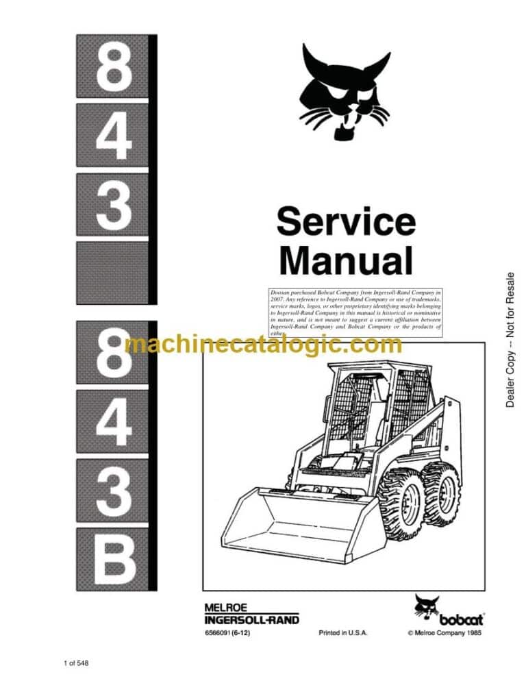
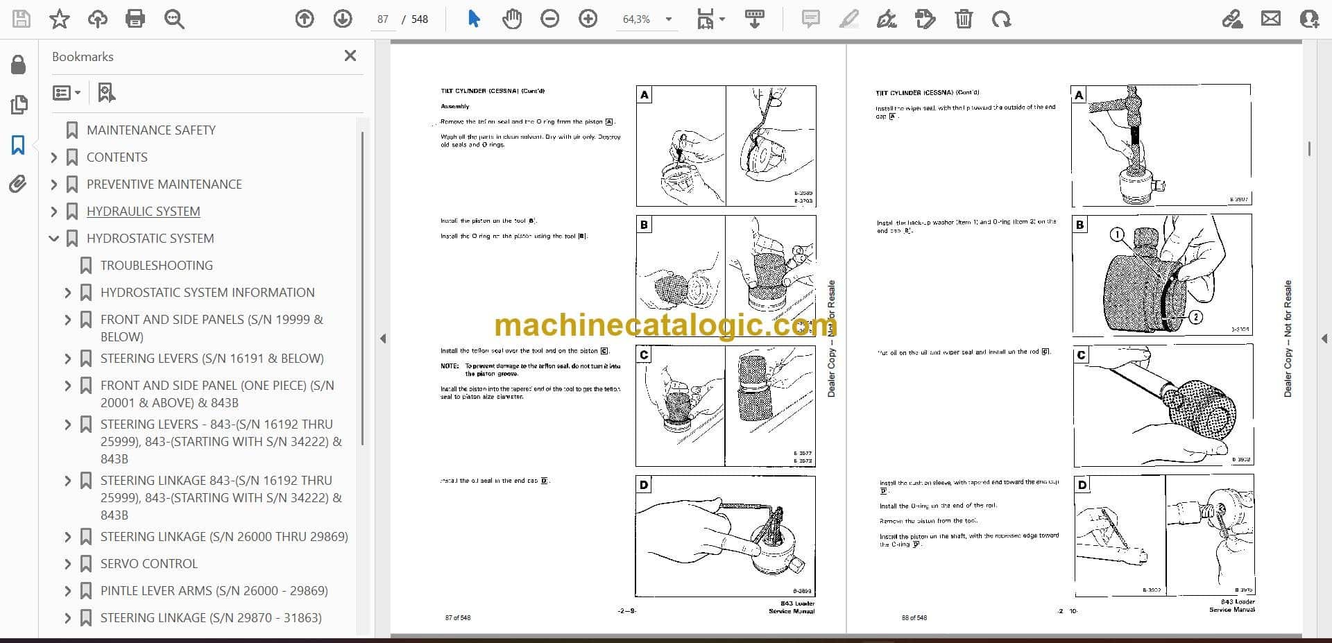
Out on a job, the Bobcat 843 is your dirt mover and pallet hauler, and when it quits, you're bleeding money until it runs again. Around my shop, this kind of service manual is what I grab when I'm past simple checks and actually tearing into the machine. Field techs and owners use it when they need real repair info, not safety stickers and daily checks. If you're chasing a hydraulic problem, electrical fault, or doing engine work, this is the level of book you want.
What this manual helps you do
- Diagnose hydraulic issues by checking pressures and tracing oil flow through the loader's circuits
- Trace and troubleshoot electrical faults using wiring diagrams and step-by-step test procedures
- Follow teardown and reassembly steps for the engine, hydrostatic drive, and drive motors
- Replace and adjust components like control linkages, Bob-Tach parts, and brake or steering parts
- Verify specs and settings after repairs so the loader runs straight, lifts right, and doesn't cook itself
Who this is for
This manual is for a small contractor, owner-operator, rental fleet, or shop mechanic working on a Bobcat 843 within serial numbers 503724001 to 503799999. If you only need basic operating instructions or safety info, you want the operator's handbook instead, not this.
FAQ
Q: Is this a searchable PDF, and can I read the wiring diagrams clearly?
A: Yes, it's a PDF you can search, and the wiring diagrams are laid out so you can zoom in and follow individual wires.
Q: Will this cover my exact 843?
A: If your 843 serial number falls between 503724001 and 503799999, this is the right manual. Outside that range, you need a different one.
Q: Is this the right thing if I'm doing my own repairs?
A: Yes, if you're doing real repair work or diagnostics, this is the correct document. For parts lookup, you'd still want the separate parts catalog.
Bottom line: If your 843 falls in that serial range and you're actually turning wrenches on it, this is the right manual. If not, skip it and match your serial first.
📘 Show Index
Table of Contents:
- MAINTENANCE SAFETY
- CONTENTS
- FOREWORD
- SAFETY INSTRUCTIONS
- FIRE PREVENTION
- SERIAL NUMBER LOCATIONS
- LOADER SERIAL NUMBER
- ENGINE SERIAL NUMBER
- DELIVERY REPORT
- BOBCAT LOADER IDENTIFICATION
- PREVENTIVE MAINTENANCE
- SERVICE SCHEDULE
- LIFTING AND BLOCKING THE LOADER
- TRANSPORTING THE BOBCAT LOADER
- LIFT ARM STOP
- OPERATOR CAB
- Seat Bar System
- Seat Bar Inspection
- Seat Bar Maintenance
- Raising The Operator Cab
- Lowering The Operator Cab
- USING AN EXTRA BATTERY (JUMP STARTING)
- REMOTE START SWITCH
- HYDRAULIC SYSTEM
- HYDRAULIC / HYDROSTATIC SCHEMATICS
- TROUBLESHOOTING
- HYDRAULIC SYSTEM INFORMATION
- Flare Connections
- Straight Thread O-Ring Fitting
- Tubelines And Hoses
- LIFT CYLINDER
- Checking The Lift Cylinder(s)
- Removal And Installation
- TILT CYLINDERS
- Checking The Tilt Cylinder
- Removal And Installation
- Rod End Seal
- TILT CYLINDER (CESSNA)
- HYDRAULIC CYLINDER REPAIR
- HYDRAULIC CONTROL VALVE (CESSNA)
- Checking The Main Relief Valve
- Main Relief Valve Removal And Installation
- Removal And Installation
- Disassembly
- Inlet Section
- Tilt Section
- Lift Section
- Auxiliary Section
- Valve Spool Bolt
- Assembly
- HYDRAULIC CONTROL VALVE (MELROE)
- Checking The Main Relief Valve
- Main Relief Valve Removal And Installation
- Removal And Installation
- Disassembly And Assembly
- Detent Assembly
- Centering Mechanism
- HYDRAULIC PUMP (SINGLE STAGE)
- Checking The Output Of The Hydraulic Pump
- Removal And Installation
- Disassembly And Assembly
- Inspection
- HYDRAULIC PUMP (DOUBLE STAGE)
- Removal And Installation
- Disassembly And Assembly
- Inspection
- BUCKET POSITION VALVE (S/N 15001 & ABOVE)
- Removal And Installation
- Disassembly And Assembly
- PORT BLOCK (S/N 14999 & BELOW)
- 40 Micron Filter (Bronze)
- Neutral By-Pass Valve
- Removal And Installation
- PORT BLOCK (S/N 15001 & ABOVE)
- Removal And Installation
- Charge By-Pass
- Cold Oil By-Pass
- HYDRAULIC FLUID FILTER HOUSING (S/N 15001 & ABOVE)
- Removal And Installation
- By-Pass Valve
- HYDRAULIC/HYDROSTATIC RESERVOIR (S/N 21514 & BELOW)
- HYDRAULIC CONTROL PEDALS (S/N 14999 & BELOW)
- Removal And Installation
- Adjustment
- HYDRAULIC CONTROL PEDALS (S/N 15001 & ABOVE)
- Removal And Installation
- Adjustment
- PEDAL LOCK LINKAGE
- HYDROSTATIC SYSTEM
- TROUBLESHOOTING
- HYDROSTATIC SYSTEM INFORMATION
- High Pressure Relief/Replenishing Valves Function
- FRONT AND SIDE PANELS (S/N 19999 & BELOW)
- STEERING LEVERS (S/N 16191 & BELOW)
- Removal And Installation
- Repairing The Steering Levers
- Steering Linkage Adjustment
- Removal And Installation
- RepairingThe Pintle Lever
- FRONT AND SIDE PANEL (ONE PIECE) (S/N 20001 & ABOVE) & 843B
- STEERING LEVERS – 843-(S/N 16192 THRU 25999), 843-(STARTING WITH S/N 34222) & 843B
- Removal And Installation
- Repairing The Steering Levers
- STEERING LINKAGE 843-(S/N 16192 THRU 25999), 843-(STARTING WITH S/N 34222) & 843B
- Steering Linkage Adjustment
- Removal And Installation
- Repairing The Pintle Lever
- STEERING LINKAGE (S/N 26000 THRU 29869)
- Description
- Neutral Adjustment
- Steering Lever Centering Spring Mechanism
- Removal And Installation (Creep Mechanism)
- SERVO CONTROL
- Removal And Installation
- Disassembly And Assembly
- PINTLE LEVER ARMS (S/N 26000 – 29869)
- STEERING LINKAGE (S/N 29870 – 31863)
- Description
- Neutral Adjustment
- Steering Lever Centering Spring Mechanism
- Creep Centering Spring Mechanism
- Pintle Arm
- STEERING LINKAGE (S/N 31864-34221)
- Hydrostatic Pump Centering Spring Adjustment
- Servo Control Unit Adjustment
- Steering Lever Centering Spring Adjustment
- Wheel RPM Adjustment (Left To Right)
- HYDROSTATIC MOTOR
- Removal And Installation
- Disassembly And Assembly
- Inspection
- Timing The Hydrostatic Motor
- High Pressure Hose Routing
- HYDROSTATIC PUMPS
- Checking The High Pressure Relief/Replenishing Valve
- Checking Charge Pressure
- Removal And Installation
- Disassembly And Assembly
- Rear Pump
- Front Pump
- Inspection
- Tow Valves
- Hydrostatic Pump Rear Mount (S/N 21574 & Above)
- HYDROSTATIC FLUID FILTER HOUSING
- DRIVE SYSTEM
- PARKING BRAKE
- Adjustment
- Removal And Installation
- Block And Pucks
- AXLES, SEALS AND BEARINGS
- FINAL DRIVE CHAIN
- REDUCTION GEARCASE
- Removal And Installation
- Checking Reduction Gearcase
- Disassembly And Assembly
- Installation
- Reduction Gearcase Seal
- MAIN FRAME
- OPERATOR CAB (S/N 19999 & BELOW)
- OPERATOR CAB (S/N 20001 & ABOVE)
- OPERATOR CAB GAS CYLINDER
- REAR DOOR
- Door Latch Adjustment
- Removal And Installation
- LIFT ARMS
- BOB-TACH
- Removal And Installation
- Tilt Cylinder Rod End Seal
- Disassembly And Assembly
- FUEL TANK (S/N 19999 & BELOW)
- FUEL TANK (S/N 20001 & ABOVE)
- Removal And Installation
- Fuel Tank Sender Switch
- ELECTRICAL SYSTEM
- ELECTRICAL SCHEMATICS
- ELECTRICAL SYSTEM INFORMATION
- TROUBLESHOOTING
- BATTERY
- Checking The Battery
- Removal And Installation
- ALTERNATOR
- Alternator Belt Adjustment
- Checking The Alternator Wire Harness
- Checking Alternator Output
- Checking Alternator Regulator
- Removal And Installation
- Disassembly And Assembly
- MELROE ALTERNATOR
- Checking The Alternator Output
- Checking The Alternator Regulator
- Removal And Installation
- Disassembly And Assembly
- MANDO ALTERNATOR
- STARTER
- Checking The Starter
- Removal And Installation
- Disassembly And Assembly
- Cleaning And Inspection
- Replacing The Brushes
- ENGINE SERVICE
- ENGINE SERVICE (PERKINS ENGINE)
- TROUBLESHOOTING
- VALVE CLEARANCE
- ENGINE COMPRESSION
- FUEL FILTER
- Removal And Installation
- Water Trap
- FUEL LIFT PUMP
- Checking
- Removal And Installation
- REMOVING AIR FROM FUEL SYSTEM
- FUEL INJECTION PUMP
- ENGINE TIMING TO INJECTION PUMP (USING DIAL INDICATOR)
- EMGINE TIMING TO INJECTOR PUMP (USING TIMING TOOL)
- CHECKING TIMING MARK ON INJECTION PUMP FLANGE
- FUEL INJECTOR NOZZLES
- Removal And Installation
- Checking
- ENGINE
- RADIATOR
- OIL COOLER
- ENGINE MUFFLER
- ENGINE BLOWER HOUSING
- ENGINE FLYWHEEL & U-JOINT
- Removal And Installation
- Flywheel Ring Gear
- CYLINDER HEAD
- Removing The Cylinder Head
- Cylinder Head Surface Alignment
- Installing The Cylinder Head
- VALVES
- Removal Of The Valves
- Installing The Valves
- Reconditioning The Valves And Valve Seats
- Installing Valve Guides
- Changing The Valve Springs
- COMBUSTION CHAMBER INSERTS
- ROCKER ARMS
- PISTON AND CONNECTING RODS
- Removal
- Disassembly
- Inspection
- Installation
- CYLINDER LINERS
- Checking
- Removal And Installation
- MAIN BEARINGS
- Removal
- Installation
- Crankshaft End Play
- CRANKSHAFT
- Removal
- Checking
- Installation
- REAR MAIN OIL SEAL
- TIMING CASE COVER
- IDLER GEAR AND HUB
- CAMSHAFT GEAR
- FUEL INJECTION PUMP DRIVE GEAR
- CRANKSHAFT GEAR
- TIMING CASE
- CAMSHAFT AND TAPPETS
- Removal
- Inspection
- Installation
- LUBRICATION SYSTEM
- OIL PUMP
- Removal And Installation
- Disassembly And Assembly
- Checking
- WATER PUMP
- Removal And Installation
- Disassembly
- Checking
- Assembly
- THERMOSTAT
- Removal
- Testing The Thermostat
- Installation
- ENGINE SERVICE (PERKINS ENGINE – 200 SERIES)
- TROUBLESHOOTING
- VALVE CLEARANCE
- ENGINE COMPRESSION
- FUEL FILTER (S/N 13315 & BELOW)
- Removal And Installation
- Water Trap
- FUEL FILTER (S/M 13316 & ABOVE)
- REMOVING AIR FROM THE FUEL SYSTEM (S/N 13315 & BELOW)
- REMOVING AIR FROM THE FUEL SYSTEM (S/N 13316 & ABOVE)
- FUEL INJECTION PUMP
- Removal And Installation
- Maximum Speed Setting
- TIMING THE FUEL INJECTION PUMP
- FUEL INJECTOR NOZZLES
- Removal And Installation
- Checking
- GLOW PLUGS
- ENGINE
- RADIATOR
- OIL COOLER
- ENGINE MUFFLER
- ENGINE BLOWER HOUSING
- ENGINE FLYWHEEL & U-JOINT
- Removal And Installation
- Flywheel Ring Gear
- CYLINDER HEAD
- Removing The Cylinder Head
- Cylinder Head Surface Alignment
- Installing The Cylinder Head
- VALVES
- Removing The Valves
- Installing The Valves
- Reconditioning The Valves And Valve Seats
- Installing The Valve Guides
- Checking The Valve Springs
- CONBUSTION CHAMBER INSERTS
- ROCKER ARMS
- PISTON AND CONNECTING RODS
- Removal
- Disassembly
- Inspection
- Installation
- CYLINDER LINERS
- Checking
- Removal And Installation
- MAIN BEARINGS
- Removal
- Installation
- Crankshaft End Play
- CRANKSHAFT
- REAR MAIN OIL SEAL
- TIMING CASE COVER
- Removal And Installation
- Front Seal
- IDLER GEAR AND HUB
- CAMSHAFT GEAR
- FUEL INJECTION PUMP DRIVE GEAR
- CRANKSHAFT GEAR
- TIMING CASE
- CAMSHAFT AND TAPPETS
- Removal
- Inspection
- Installation
- LUBRICATION SYSTEM
- OIL PUMP
- Removal And Installation
- Inspection
- OIL FILTER ADAPTER HOUSING
- WATER PUMP
- Removal And Installation
- Disassembly
- Checking
- Assembly
- THERMOSTAT
- Removal
- Testing The Thermostat
- Installation
- ENGINE SERVICE (ISUZU ENGINE)
- TROUBLESHOOTING
- VALVE CLEARANCE
- ENGINE COMPRESSION
- FUEL FILTER
- Water Trap
- Fuel Filter Element
- REMOVING AIR FROM FUEL SYSTEM
- FUEL INJECTION PUMP
- ENGINE TIMING TO INJECTION PUMP
- FUEL INJECTOR NOZZLES
- Removal And Installation
- Checking
- GLOW PLUGS
- ENGINE OIL AND FILTER
- ENGINE
- RADIATOR
- OIL COOLER
- ENGINE MUFFLER
- ENGINE FLYWHEEL & U-JOINT
- Removal And Installation
- Flywheel Ring Gear
- ENGINE BLOWER HOUSING
- ENGINE MOUNTS
- CYLINDER HEAD
- Removal And Installation
- Cylinder Head Surface Alignment
- Exhaust Manifold
- VALVES
- Removal And Installation
- Reconditioning The Valves And Valve Seats
- Valve Seat Insert
- Valve Guides
- Valve Springs
- ROCKER ARMS
- Disassembly And Assembly
- Push Rods
- PISTON AND CONNECTING ROD
- Removal
- Disassembly
- Inspection
- Assembly
- Installation
- CYLINDER LINERS
- Checking
- Removal
- Installation
- MAIN BEARINGS
- Removal
- Installation
- Crankshaft End Play
- CRANKSHAFT
- Removal
- Checking Tuffriding (Soft Nitriding) Coating
- Checking
- Crankshaft Gear
- Removal And Installation
- Installation
- TIMING CASE COVER SEAL
- TIMING CASE COVER
- IDLER GEAR AND HUB
- Removal And Installation
- Checking
- FUEL INJECTION PUMP IDLER GEAR
- Removal And Installation
- Bearing Installation
- CAMSHAFT GEAR
- TIMING CASE
- CAMSHAFT
- Removal And Installation
- Checking
- Camshaft Bearing
- Tappets
- Installation
- OIL PAN
- OIL PUMP
- Removal And Installation
- Checking
- Gear Replacement
- Rotor Replacement
- Oil Pump Relief Valve
- WATER PUMP
- Removal And Installation
- Disassembly
- Assembly
- THERMOSTAT
- Removal And Installation
- Inspection
- WATER JACKET TUBE
- TECHNICAL DATA
- GENERAL SPECIFICATIONS
- TORQUE SPECIFICATIONS
- Seat Bar, Fuel Tank & Panel Group
- Steering Levers, Linkage & Pedal Group
- Brakem Axle & Chaincase Group
- Operator Guard, Lift Arm & Main Frame Group
- Hydraulic/Hydrostatic Group
- Engine Group (Perkins)
- Engine Group (200 Series Perkins)
- Engine Group (Isuzu)
- HYDRAULIC/HYDROSTATIC FLUID SPECIFICATIONS
- DECIMAL AND MILLIMETER EQUIVALENTS
- U.S. TO METRIC CONVERSION
- STANDARD TORQUE SPECIFICATIONS FOR BOLTS
- TECHNICAL DATA (PERKINS ENGINE)
- LOADER SPECIFICATIONS
- Specifications
- Engine
- Loader Hydraulics
- Electrical
- Drive System
- Capacities
- Tires
- ENGINE SPECIFICATIONS
- Cylinder Head Dimensions
- Piston And Connecting Rod Dimensions
- Cylinder Block And Liner Dimensions
- crankshaft And Main Bearings Dimensions
- Timing Case, Camshaft And Drive Dimensions
- Oil Pump Dimensions
- Cooling System and Wster Pump Dimensions
- Fuel System Specifications
- De-Rating For Altitude
- Engine Torque
- Grinding Specifications For Crankshaft
- TECHNICAL DATA (PERKINS ENGINE – 200 SERIES)
- LOADER SPECIFICATIONS
- Specifications
- Engine
- Loader Hydraulics
- Electrical
- Drive System
- Capacities
- Tires
- ENGINE SPECIFICATIONS
- Cylinder Head Dimensions
- Pistons And Connecting Rod Dimensions
- Cylinder Block And Liner Dimensions
- Crankshaft And Main Bearing Dimensions
- Timing Case, Camshaft And Drive Dimensions
- Oil Pump Dimensions
- Cooling System And Water Pump Dimensions
- Fuel System Specifications
- De-Rating For Altitude
- Engine Torques
- Grinding Specifications For Crankshaft
- TECHNICAL DATA (iSUZU ENGINE)
- LOADER SPECIFICATIONS
- Operation And Performance
- Engine
- Loader Hydraulics
- Electrical
- Drive System
- Capacities
- Tires
- ENGINE SPECIFICATIONS
- Cylinder Head
- Valve, Vale Guide And Seat Insert
- Valve Springs
- Rocker Arm
- Tappets
- Piston, Pin And Rings
- Connecting Rod & Bearing
- Cylinder Liners
- Camshaft
- Crankshaft
- Idler Gear
- Oil Pump
- Fuel System
- Engine Torque
- SERVICE MANUAL REVISIONS
- 843-1
- 843-2
- 843-3
- 843-4
- 843-5
- 843-6
- 843-7
- 843-8
- 843-9
- 843-10
- 843-11
- 843-12
- 843-13
- 843-14
- 843-15
- 843-16
- 843-17
Bobcat Software
Bobcat PDF Manuals