$ 0
0
$ 0
0

Bobcat 853 Loader Service Manual (SN 512311001-512399999)

Format: PDF (Printable Document)

File Language: English

File Pages: 398

File Size: 10.41 MB (Speed Download Link)

Brand: Bobcat

Model: 853 Loader

Book No: 6720755

Serial No: SN 512311001-512399999

Type of Document: Service Manual

Categories: ,

$ 45

Share:

Bobcat 853 Loader Service Manual (SN 512311001-512399999)

A Bobcat 853 is a mid-size skid-steer that spends its life loading trucks, running augers, forks, and snow gear in tight spaces. The people who reach for this service manual are the ones actually turning wrenches: small contractors, owner-operators, field techs like me, and shop mechanics. They're trying to get hard numbers and step-by-step sequences so they don't guess on hydraulic tests, wiring checks, or teardown order and then lose half a day waiting on parts or a tow.

What this manual helps you do

  • Diagnose hydraulic and hydrostatic issues, then check pressures and flow using the correct test ports and sequences.
  • Trace electrical faults, using wiring diagrams to chase dead circuits, bad relays, and sensor problems instead of just swapping parts.
  • Follow teardown and reassembly steps on the engine, pumps, drive motors, and cylinders so you don't miss seals, shims, or timing marks.
  • Adjust linkages, controls, and Bob-Tach components so the loader arms, pedals, and auxiliary hydraulics respond the way they should.
  • Replace major components and verify they're installed and bled correctly before you back the machine off the trailer.

Who this is for

This manual is for anyone working on a Bobcat 853 loader in the serial range 512311001-512399999, whether you're a small contractor, rental yard, or field mechanic. If you just need basic controls, safety, and daily checks, you want the operator's handbook instead, not this service manual.

FAQ

Q: Is this a searchable PDF, and can I read the wiring diagrams clearly?

A: These manuals are usually text-searchable, and the wiring diagrams are normally clear enough to zoom in on a laptop or tablet in the truck.

Q: How do I know it fits my exact 853?

A: If your machine's serial number falls between 512311001 and 512399999, this is the correct service manual for it.

Q: Is this the right document if I'm doing real repairs, not just maintenance?

A: Yes, this is the workshop-level service manual, meant for diagnosis and repair, not just fluid changes.

Bottom line: If your 853's serial number is in that range and you're doing your own repairs or diagnostics, this is the manual you want.

📘 Show Index

Table of Contents:

  • MAINTENANCE SAFETY
  • ALPHABETICAL INDEX
  • CONTENTS
    • FOREWORD
    • SAFETY INSTRUCTIONS
    • SERIAL NUMBER LOCATIONS
    • LOADER SERIAL NUMBER
    • ENGINE SERIAL NUMBER
    • DELIVERY REPORT
    • BOBCAT LOADER IDENTIFICATION
  • PREVENTIVE MAINTENANCE
    • SERVICE SCHEDULE
    • LIFTING AND BLOCKING THE LOADER
      • Procedure
    • TRANSPORTING THE LOADER
      • Procedure
    • TOWING THE LOADER
      • Procedure
    • LIFTING THE LOADER
      • Four Point Lift
      • Single Point Lift
    • LIFT ARM SUPPORT DEVICE
      • Engaging The Lift Arm Support Device
      • Disengaging The Lift Arm Support Device
    • OPERATOR CAB
      • Description
      • Raising The Operator Cab
      • Lowering The Operator Cab
      • Emergency Exit
    • SEAT BAR RESTRAINT SYSTEM
      • Description
      • Inspecting The Seat Bar
      • Maintaining The Seat Bar
    • AIR CLEANER SERVICE
      • Replacing Filter Element
    • FUEL SYSTEM
      • Fuel Specifications
      • Filling The Fuel Tank
      • Fuel Filter
      • Removing Air From The Fuel System
    • ENGINE LUBRICATION SYSTEM
      • Checking Engine Oil
      • Replacing Oil And Filter
    • ENGINE COOLING SYSTEM
      • Checking The Coolant Level
      • Cleaning The Cooling System
      • Replacing The Coolant
    • ALTERNATOR BELT
      • Adjusting The Alternator Belt
    • HYDRAULIC/HYDROSTATIC SYSTEM
      • Checking And Adding Fluid
      • Replacing Hydraulic/Hydrostatic Filters
      • Replacing The Hydraulic Fluid
      • Hydraulic Reservoir Breather Cap
    • SPARK ARRESTOR MUFFLER
      • Cleaning Procedure
    • TIRE MAINTENANCE
      • Wheel Nuts
      • Tire Rotation
      • Tire Mounting
    • FINAL DRIVE TRANSMISSION (CHAINCASE)
      • Checking And Adding Oil
    • FAN GEARBOX
      • Checking And Maintaining
    • LUBRICATING THE LOADER
      • Procedure
    • REMOTE START SWITCH
      • Procedure
  • HYDRAULIC SYSTEM
    • HYDRAULIC/HYDROSTATIC SCHEMATICS
    • TROUBLESHOOTING
    • HYDRAULIC SYSTEM INFORMATION
      • Tighten Procedures
    • LIFT CYLINDER(S)
      • Checking The Lift Cylinder
      • Removal And Installation
    • TILT CYLINDER
      • Checking The Tilt Cylinder
        • Rod End Seal
        • HYDRAULIC CYLINDER
        • Lift Cylinder Identification
        • Tilt Cylinder Identification
        • Disassembly
        • Assembly
    • MAIN RELIEF VALVE
      • Checking The Main Relief Valve
      • Checking The Main Relief Valve Without Auxiliaries
      • Removal And Installation
    • DUAL PRESSURE MAIN RELIEF VALVE (S/N 512811001 & Above) W/ Select Valve (JEM)
      • Checking The Low Setting
      • Checking The High Setting
      • Adjusting The Low Setting
      • Adjusting The High Setting
    • HYDRAULIC CONTROL VALVE
      • Removal And Installation
    • SELECT VALVE (S/N 512811001 & Above) W/SelectValve (JEM)
      • Checking The Relief Valve
      • Removal And Installation
      • Disassembly And Assembly
      • Solenoid Testing
    • HYDRAULIC FILTER HOUSING
      • Removal And Installation
    • HYDRAULIC PUMP
      • Checking The Output Of The Pump
      • Removal And Installation
    • HYDRAULIC FLUID RESERVOIR
      • Removal And Installation
    • LOCK VALVE (S/N 5103)
      • Removal And Installation
    • BUCKET POSITION VALVE (S/N 5102) & (S/N 5103)
      • Removal And Installation
    • FRONT AUXILIARY CONTROL VALVE (Apitech)
      • Removal And Installation
    • CONTROL PEDALS
      • Removal And Installation
      • Pedal Adjustment
    • PEDAL INTERLOCK LINKAGE
      • Removal And Installation
      • Pedal Interlock Linkage Adjustment
  • HYDROSTATIC SYSTEM
    • TROUBLESHOOTING
    • HYDROSTATIC SYSTEM INFORMATION
      • Replenishing Valve Function
      • Tow Valves
    • FRONT PANEL
      • Removal And Installation
    • STEERING LEVERS
      • Disassembly And Assembly
      • Neutral Pre–Adjustment Checks
      • Adjusting Lever Freeplay
      • Adjusting The Wheel RPM Forward Compared To Reverse Travel
      • Adjusting The Steering Neutral Setting
      • Adjusting The Wheel RPM Left Compared To Right Side
      • Hydrostatic Pump Neutral Adjustment
    • HYDROSTATIC MOTOR
      • Removal And Installation
    • HYDROSTATIC CHARGE OIL FILTER
      • Removal And Installation
    • COLD OIL BY–PASS VALVE
      • Removal And Installation
    • HYDROSTATIC PUMP
      • Removal And Installation
      • Replenishing/High Pressure Relief Valve
    • DRIVE BELT SHIELD
      • Removal And Installation
    • DRIVE BELT
      • Replacing The Drive Belt
    • SPRING LOADED TENSIONER PULLEY
      • Parts Identification
      • Disassembly
      • Assembly
      • Adjusting The Drive Belt
    • FIXED TENSIONER PULLEY
      • Removal And Installation
      • Disassembly
      • Assembly
      • Checking Pulley End Play
      • Adjusting The Drive Belt
    • OIL COOLER
      • Removal And Installation
  • DRIVE SYSTEM
    • PARKING BRAKE PEDAL
      • Adjustment
    • PARKING BRAKE
      • Removal And Installation
      • Brake Block And Pads
      • Brake Discs
    • FRONT CHAINCASE COVER
      • Removal And Installation
    • REAR CHAINCASE COVER
      • Removal And Installation
    • AXLE SEAL
      • Removal And Installation
    • AXLE, SPROCKET AND BEARINGS
      • Removal And Installation
    • REDUCTION GEARCASE
      • Reduction Gearcase Seal
      • Removal And Installation
      • Checking Reduction Gearcase
      • Disassembly
      • Assembly
    • DRIVE CHAIN
      • Removal And Installation
    • CHAINCASE FLUID
      • Removing The Fluid From The Chaincase
  • MAIN FRAME
    • OPERATOR CAB GAS CYLINDER
      • Removal And Installation
      • Disassembly And Assembly
    • OPERATOR CAB
      • Removal And Installation
      • BOB–TACH
      • Removal And Installation
      • Bob–Tach Lever And Wedge
      • Bob–Tach Stops
    • LIFT ARMS
      • Removal And Installation
    • REAR GRILL
      • Removal And Installation
    • REAR DOOR
      • Removal And Installation
      • Hood Removal And Installation
      • Bumper Removal And Installation
      • Door Latch Removal And Installation
      • Door Latch And Catch Adjustment
    • FUEL TANK
      • Removal And Installation
      • Inlet Screen
  • ELECTRICAL SYSTEM
    • ELECTRICAL SCHEMATICS
    • TROUBLESHOOTING
    • ELECTRICAL SYSTEM INFORMATION
      • Description
      • Fuse Location
    • BATTERY
      • Removal And Installation
      • Servicing The Electrical System
      • Using A Booster Battery (Jump Starting)
    • ALTERNATOR
      • Alternator Output Test
      • Rectifier (Diode) Test
      • Alternator Regulator Test
      • Removal And Installation
      • Disassembly
      • Stator Continuity Test
      • Stator Ground Test
      • Rotor Continuity Test
      • Rotor Ground Test
      • Rectifier Continuity (Diode) Test
      • Assembly
    • STARTER
      • Checking The Starter
      • Removal And Installation
      • Parts Identification
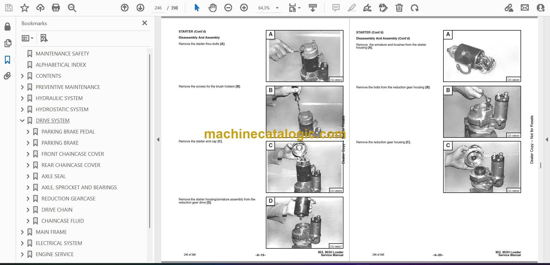
      • Disassembly And Assembly
      • Cleaning And Inspection
    • STANDARD INSTRUMENT PANEL
      • Removal And Installation
    • FRONT LIGHTS
      • Removal And Installation
    • STEERING LEVER CONTROL HANDLE (Early Series)
      • Disassembly And Assembly
  • ENGINE SERVICE
    • TROUBLESHOOTING
    • ENGINE SPEED CONTROL
      • Removal And Installation
    • ENGINE MUFFLER
      • Removal And Installation
    • AIR CLEANER HOUSING
      • Removal And Installation
    • COOLANT RECOVERY TANK
      • Removal And Installation
    • RADIATOR
      • Removal And Installation
    • FAN DRIVE TENSION PULLEY
      • Removal And Installation
    • FAN GEARBOX/BLOWER HOUSING
      • Removal And Installation
    • FAN GEARBOX
      • Parts Identification
      • Disassembly
      • Assembly
      • Checking Backlash
    • ENGINE
      • Removal And Installation
    • FLYWHEEL
      • Removal And Installation
      • Flywheel Ring Gear
    • BELT SHIELD
      • Removal And Installation
    • ENGINE MOUNTS
      • Removal And Installation
    • GLOW PLUGS
      • Checking The Glow Plugs
      • Removal And Installation
    • VALVE CLEARANCE
      • Adjustment
    • ENGINE COMPRESSION
      • Checking
    • FUEL INJECTION PUMP
      • Description
      • Removal And Installation
      • Timing The Injection Pump
    • FUEL INJECTOR NOZZLES
      • Checking
      • Removal And Installation
    • CYLINDER HEAD
      • Removal And Installation
      • Cylinder Head Surface Alignment
      • Exhaust Manifold
    • VALVES, VALVE SEAT AND GUIDE
      • Removal
      • Installation
      • Reconditioning The Valve And Valve Seats
      • Valve Seat Insert
      • Valve Guide
      • Valve Spring
    • ROCKER ARM AND SHAFT
      • Disassembly And Assembly
      • Checking Rocker Arm And Push Rods
    • PISTON AND CONNECTING ROD
      • Removal
      • Disassembly
      • Checking
      • Assembly
      • Installation
    • CYLINDER LINERS
      • Checking The Cylinder Bore
      • Removal
      • Installation
    • MAIN BEARINGS
      • Description
      • Removal
      • Installation
      • Crankshaft End Play
    • CRANKSHAFT
      • Removal And Installation
      • Checking The Crankshaft
    • CRANKSHAFT GEAR
      • Removal And Installation
    • TIMING GEARCASE COVER SEAL
      • Removal And Installation
    • TIMING GEARCASE COVER
      • Removal And Installation
    • IDLER GEAR AND HUB
      • Checking
      • Installation
    • FUEL INJECTION PUMP IDLER GEAR
      • Removal And Installation
      • Bearing Installation
    • CAMSHAFT GEAR
      • Removal And Installation
    • TIMING GEARCASE
      • Removal And Installation
    • CAMSHAFT
      • Removal And Installation
      • Checking
      • Camshaft Bearings
      • Tappets
      • Tappet Installation
    • OIL PAN
      • Removal
      • Installation
    • OIL PUMP
      • Removal And Installation
      • Checking
      • Gear Replacement
      • Rotor Replacement
      • Oil Pump Relief Valve
      • Oil Filter Housing And Block
    • WATER PUMP
      • Removal And Installation
      • Disassembly
      • Assembly
    • THERMOSTAT
      • Removal And Installation
      • Checking The Thermostat
    • WATER JACKET TUBE
      • Removal And Installation
  • SYSTEM ANALYSIS
    • BOSS® DIAGNOSTIC TOOL
      • Procedure
    • SENDER AND SENSOR
      • Service Checks
      • Component
    • RPM SENSOR
      • Adjustment
    • SERVICE CODES
      • Chart
    • TROUBLESHOOTING THE BOSS® & LCD DISPLAY
    • BOSS® UNIT
      • Removal And Installation
    • BOSS® INSTRUMENT PANEL
      • Removal And Installation
  • SPECIFICATIONS
    • LOADER SPECIFICATIONS
      • Loader Dimensions
      • Performance
      • Controls
      • Engine
      • Hydraulic System
      • Electrical
      • Drive System
      • Capacities
      • Tires
    • ENGINE SPECIFICATIONS
      • Cylinder Head
      • Valve, Valve Guide & Seat Insert
      • Valve Springs
      • Rocker Arm
      • Tappets
      • Piston, Pin & Rings
      • Connecting Rod & Bearing
      • Cylinder Liners
      • Camshaft
      • Crankshaft
      • Idler Gear
      • Oil Pump
      • Fuel System
    • TORQUE SPECIFICATIONS FOR LOADER
    • TORQUE SPECIFICATIONS FOR BOLTS
      • Torque For General SAE Bolts
      • Torque For General Metric Bolts
    • HYDRAULIC CONNECTION SPECIFICATIONS
      • O–ring Face Seal Connection
      • Straight Thread O–ring Fitting
      • Tubelines And Hoses
      • Flare Fitting
      • O–ring Flare Fitting
      • Port Seal Fitting
    • HYDRAULIC/HYDROSTATIC FLUID SPECIFICATIONS
    • DECIMAL AND MILLIMETER EQUIVALENTS
    • U.S. TO METRIC CONVERSION
  • SERVICE MANUAL REVISIONS
    • 850–001
    • 850–002
    • 850–003
    • 850–004
    • 850–005
    • 850–006
    • 850–007
    • 850–008
    • 850–009
    • 850–010
    • 850–011
    • 850–012
    • 850–13
    • 850-14
    • 850-15

Bobcat Software

Bobcat PDF Manuals

Related Manuals

0
    0
    Your Cart
    Your cart is emptyReturn to Shop