The MT52 is that walk-behind mini track loader you stuff into backyards and tight spots where a full skid won't fit. On real jobs it's running augers, buckets, and trenchers all day, so the hydrostat, drive motors, and small diesel work hard. People grab the service manual when the machine is out of warranty and they need real specs and tear-down steps, not sales fluff. Around my shop it's what I open when I'm chasing a drive issue, an electrical gremlin, or oil where it shouldn't be.
What this manual helps you do
- Diagnose no-move, weak drive, or tracking issues in the hydrostatic system and drive motors
- Check and set hydraulic and hydrostatic test ports using proper pressure and flow procedures
- Follow step-by-step removal and installation of pumps, motors, cylinders, and the Bob-Tach style mount system
- Trace and troubleshoot wiring, safety interlocks, and charging system faults using full schematics
- Rebuild and adjust mechanical linkages, controls, and undercarriage components after wear or replacement
Who this is for
This is for anyone working on a Bobcat MT52 in the serial range 528811001-528899999: small contractors, rental fleets, owner-operators, or shop mechanics who already know their way around Cat and Deere compacts. If you only want how to drive it or daily checks, you want the operator's handbook instead, not this service manual.
FAQ
Q: Is this a searchable PDF and are the wiring diagrams readable?
A: Yes, these manuals are usually searchable PDFs and the wiring diagrams are clear enough to zoom and trace circuits on a laptop or tablet.
Q: Does it cover my exact MT52?
A: If your serial number falls between 528811001 and 528899999, this is the correct manual. If it does not, you need the book that matches your serial range.
Q: Is this the right thing if I'm only doing filters and fluid changes?
A: Probably overkill. Basic maintenance is in the operator's handbook; this manual is for deeper diagnostics and repairs.
Bottom line: If your MT52 serial number is in that range and you're doing real repair or diagnostic work, this is the right manual. If not, skip it and match the serials first.
📘 Show Index
Table of Contents:
- MAINTENANCE SAFETY
- ALPHABETICAL INDEX
- CONTENTS
- FOREWORD
- SAFETY INSTRUCTIONS
- SERIAL NUMBER LOCATION
- Loader Serial Number
- Engine Serial Number
- DELIVERY REPORT
- BOBCAT LOADER IDENTIFICATION
- SAFETY AND MAINTENANCE
- LIFTING AND BLOCKING THE LOADER
- Procedure
- Four Point Lift
- LIFT ARM SUPPORT DEVICE
- TRANSPORTING THE BOBCAT LOADER
- TOWING THE LOADER
- SERVICE SCHEDULE
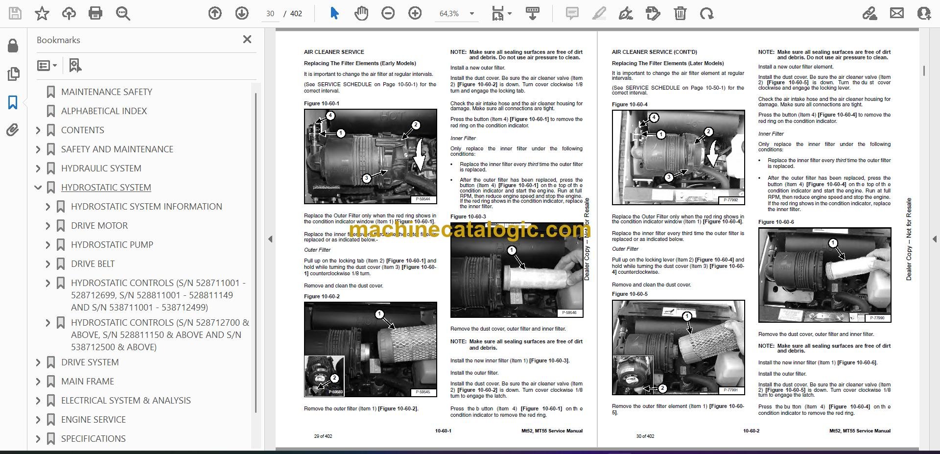
- AIR CLEANER SERVICE
- Replacing The Filter Elements (Early Models)
- Replacing The Filter Elements (Later Models)
- ENGINE COOLING SYSTEM
- Checking The Coolant Level
- Cleaning The Cooling System
- Replacing The Coolant
- FUEL SYSTEM
- Fuel Specifications
- Filling The Fuel Tank
- Fuel Filter
- Removing Air From The Fuel System
- ENGINE LUBRICATION SYSTEM
- Checking Engine Oil
- Oil Chart
- Replacing Oil And Filter
- HYDRAULIC / HYDROSTATIC SYSTEM
- Checking And Adding Fluid
- Replacing Hydraulic Filter
- Hydraulic Reservoir Breather
- Replacing Hydraulic Fluid
- BOB-TACH
- Inspection And Maintenance
- LUBRICATION OF THE BOBCAT MINI LOADER
- Procedure
- Parking Brake Lubrication
- Pivot Pins
- SPARK ARRESTOR MUFFLER
- CONTROLS
- Reverse Stop Panel
- Lift And Tilt Function Lockouts
- Lift Arm By-Pass Controls
- Neutral Start Interlocks
- ELECTRICAL SYSTEM
- Description
- Fuse And Relay Location / Identification
- Cleaning Battery Terminals
- Using A Booster Battery (Jump Starting)
- Removing And Installing The Battery
- HYDRAULIC SYSTEM
- HYDRAULIC/HYDROSTATIC SCHEMATICS
- HYDRAULIC SYSTEM INFORMATION
- Workgroup Troubleshooting Chart
- Hydraulic Function Troubleshooting
- CYLINDER (LIFT)
- Checking The Lift Cylinder(s)
- Removal And Installation
- Parts Identification
- Disassembly And Assembly
- CYLINDER (TILT)
- Checking The Tilt Cylinder
- Removal And Installation
- Rod End Pivot Pin Bushing And Seal Replacement
- Parts Identification
- Disassembly And Assembly
- MAIN RELIEF VALVE
- Checking
- Removal And Installation
- PORT RELIEF VALVES
- Checking The Port Relief Valves (Lift)
- Removal And Installation (Lift)
- Checking The Port Relief Valves (Tilt)
- Removal And Installation (Tilt)
- HYDRAULIC CONTROL VALVE
- Removal And Installation
- Parts Identification
- Identification Chart
- Disassembly and Assembly
- HYDRAULIC PUMP
- Check The Output Of The Hydraulic Pump
- Removal And Installation
- Parts Identification
- Disassembly And Assembly
- HYDRAULIC FILTER
- Housing Removal And Installation
- HYDRAULIC FLUID RESERVOIR
- HYDRAULIC OIL COOLER
- HYDROSTATIC SYSTEM
- HYDROSTATIC SYSTEM INFORMATION
- Troubleshooting Chart
- Replenishing Valve Function
- DRIVE MOTOR
- Removal And Installation
- Parts Identification
- Disassembly
- Inspection
- Assembly
- HYDROSTATIC PUMP
- Charge Pressure Sender Removal And Installation
- Checking Charge Pressure
- Replacing Poppet Assembly
- Removal And Installation
- Replenishing/High Pressure Relief Valve
- Disassembly
- Assembly
- DRIVE BELT
- Removing Drive Belt Shield
- Adjusting The Drive Belt Tension
- Drive Belt Replacement
- Tensioner Pulley Removal And Installation
- Drive Belt Alignment
- HYDROSTATIC CONTROLS (S/N 528711001 – 528712699, S/N 528811001 – 528811149 AND S/N 538711001 – 538712499)
- Steering Assembly Identification
- Steering Assembly Removal And Installation
- Steering Linkage Adjustment
- Adjusting Forward Speed Control
- Adjusting Reverse Speed Control
- HYDROSTATIC CONTROLS (S/N 528712700 & ABOVE, S/N 528811150 & ABOVE AND S/N 538712500 & ABOVE)
- Steering Assembly Identification
- Steering Assembly Removal And Installation
- Steering Linkage Adjustment
- Adjusting Reverse Speed Control
- DRIVE SYSTEM
- PARKING BRAKE
- Handle Removal And Installation
- Cable Removal And Installation
- Cable Adjustment
- Removing The Linkage Assembly
- Brake Pin Lubrication
- DRIVE COMPONENTS
- Track Tension Checking
- Adjusting The Tracks
- Track Removal and Installation
- Track Frame Removal and Installation
- Rear Idler Assembly Removal and Installation
- Parts Identification (Rear Track Idler)
- Rear Idler Disassembly and Assembly
- Front Idler Disassembly And Assembly
- Track Tensioner Disassembly and Assembly
- Track Roller Removal and Installation
- Parts Identification (Track Roller)
- Track Roller Disassembly and Assembly
- Track Damage Identification
- MAIN FRAME
- BOB-TACH
- Removal
- Installation
- Seal Removal And Installation
- Lever And Wedge Removal
- LIFT ARM
- TAILGATE
- Removal And Installation
- Rear Door Panel Removal And Installation
- Tailgate Striker Removal And Installation
- Tailgate Striker Adjustment
- Tailgate Bumper Adjustment
- FUEL TANK
- INSTRUMENT PANEL
- GRAB BAR
- HOOD
- Removal and Installation
- Disassembly And Assembly
- Hood Latch Removal
- REVERSE STOP PANEL
- Description
- Inspecting Function
- Removal And Installation
- Reverse Stop Mechanism Removal And Installation
- BOTTOM ACCESS PANEL
- RIDE-ON PLATFORM
- Removal and Installation
- Tire Removal and Installation
- Caster Removal and Installation
- ELECTRICAL SYSTEM & ANALYSIS
- ELECTRICAL SCHEMATICS
- ELECTRICAL SYSTEM INFORMATION
- Electrical Troubleshooting Chart
- BATTERY
- Removal and Installation
- Servicing
- Using A Booster Battery (Jump Starting)
- ALTERNATOR
- Removal and Installation
- Adjusting The Alternator Belt
- Description
- Tests
- Alternator Output Test
- Full Field Test
- Alternator Regulator Test
- Alternator Regulator Test Using Voltmeter
- STARTER
- Removal And Installation
- Checking The Starter In The Loader
- Parts Identification
- Disassembly
- Inspection And Repair
- No Load Test
- Assembly
- INSTRUMENT PANEL
- Component Removal And Installation
- NEUTRAL START SENSOR (S/N 528711001 – 528712429, S/N 528811001 – 528811121 AND S/N 538711001 – 538712295)
- Description
- Removal And Installation
- Sensor Activation Adjustment
- Sensor Activation Bolt Removal
- NEUTRAL START SENSOR (S/N 528712430 & aBOVE, S/N 528811122 & ABOVE AND S/N 538712296 & ABOVE)
- Description
- Removal And Installation
- Sensor Activation Adjustment
- Sensor Activation Bolt Removal
- ELECTRICAL ATTACHMENT CONTROL REFERENCE
- Attachment Control Identification Chart
- ENGINE SERVICE
- ENGINE INFORMATION AND TESTING
- Engine Troubleshooting Chart
- ENGINE SPEED CONTROL
- Removal And Installation
- Disassembly And Assembly
- Cable Removal and Installation
- MUFFLER
- AIR CLEANER
- Housing Removal and Installation
- RADIATOR
- ENGINE COMPONENTS AND TESTING
- Valve Clearance Adjustment
- Fuel Injection Pump Check
- Fuel Lift Pump Removal And Installation
- Fuel Injection Pump Removal And Installation
- Fuel Injector Nozzles Checking
- Fuel Injector Nozzles Removal
- Fuel Injector Nozzles Installation
- Glow Plugs Checking
- Engine Compression Test Procedure
- Fuel Injection Pump Timing
- ENGINE (S/N 528711001 – 528712699, S/N 528811001 – 528811149 AND S/N 538711001 – 538712499)
- Removal And Installation
- Engine Mount Replacement
- ENGINE (S/N 528712700 & ABOVE, S/N 528811150 & above AND S/N 538712500 & ABOVE)
- Removal And Installation
- Engine Mount Replacement
- FLYWHEEL
- Flywheel Removal And Installation
- Flywheel Ring Gear Removal And Installation
- RECONDITIONING THE ENGINE
- Cylinder Head Removal And Installation
- Cylinder Head Inspection
- Cylinder Head Top Clearance
- Rocker Arm And Shaft Checking
- Valve Removal
- Valve Spring Checking
- Valve Guide Checking
- Reconditioning The Valve And Valve Seat
- Timing Gearcase Cover Removal And Installation
- Idler Gear And Camshaft Removal And Installation
- Servicing The Idler Gear And Shaft
- Checking Timing Gear Backlash
- Fuel Camshaft Removal And Installation
- Governor
- Crankshaft Gear Removal And Installation
- Oil Pump Removal And Installation
- Oil Pump Service
- Checking Engine Oil Pressure
- Relief Valve
- Piston And Connecting Rod Removal And Installation
- Piston And Connecting Rod Servicing
- Connecting Rod Alignment
- Crankshaft And Bearings Removal And Installation
- Inspection Of Crankshaft And Bearings
- Cylinder Bore Inspection
- Thermostat Removal And Installation
- Testing The Thermostat
- Water Pump Removal And Installation
- Water Pump Disassembly And Assembly
- Energize To Stop Solenoid
- ENGINE MOUNTING BRACKET
- Engine Mounting Bracket Removal And Installation
- HYDRAULIC GEAR PUMP MOUNTING BRACKET
- Hydraulic Gear Pump Mounting Bracket Removal And Installation
- Hydraulic Gear Pump Coupler Removal And Installation
- SPECIFICATIONS
- LOADER SPECIFICATIONS
- Loader Dimensions (MT52)
- Loader Dimensions (MT55)
- Performance
- Controls
- Engine
- Hydraulic System
- Electrical
- Drive System
- Capacities
- Tracks
- Ground Pressure
- ENGINE SPECIFICATIONS (KUBOTA D902-E2B)
- Engine
- Fuel Injector Nozzles
- Fuel Injection Pump
- Cylinder Head
- Valves
- Valve Springs
- Rocker Arms
- Camshaft
- Cylinders
- Piston Rings
- Pistons
- Connecting Rods
- Crankshaft
- Oil Pump
- Timing Gear
- Thermostat
- Engine Bolt Torque
- ENGINE SPECIFICATIONS (KUBOTA D722-E2B)
- Engine
- Fuel Injector Nozzles
- Fuel Injection Pump
- Cylinder Head
- Valves
- Valve Springs
- Rocker Arms
- Camshaft
- Cylinders
- Piston Rings
- Pistons
- Connecting Rods
- Crankshaft
- Oil Pump
- Timing Gear
- Thermostat
- Engine Bolt Torque
- TORQUE SPECIFICATIONS FOR BOLTS
- Torque For General SAE Bolts
- Torque For General Metric Bolts
- Torque For Kubota Metric Engine Bolts
- HYDRAULIC CONNECTION SPECIFICATIONS
- O-ring Face Seal Connection
- Straight Thread O-ring Fitting
- Tubelines And Hoses
- Flare Fitting
- O-ring Flare Fitting
- Port Seal Fitting
- HYDRAULIC FLUID SPECIFICATIONS
- CONVERSIONS
- Decimal And Millimeter Equivalents
- U.S. To Metric Conversion
- SMR
- MT52, MT55-1
- MT52, MT55-2
- MT52, MT55-3
- MT52, MT55-4
- MT52, MT55-5
- MT52, MT55-6
Bobcat Software
Bobcat PDF Manuals