The 863 is a mid-size skid-steer that lives on dirt work, concrete prep, demo, and running augers and forks all week. When something quits, the guy who owns it or the tech in the truck reaches for the service manual. They're trying to get solid procedures, specs, and wiring info so they can fix it once and get the machine back making money instead of sitting on a trailer.
What this manual helps you do
- Trace and diagnose hydraulic issues in the loader and hydrostatic drive so you're not just throwing parts at it
- Check and set pressures on the hydrostatic and implement systems with the right ports and test steps
- Follow teardown and reassembly steps for drive motors, cylinders, and major hydraulic components
- Diagnose electrical faults using wiring diagrams and step-by-step checks for switches, sensors, and relays
- Replace and adjust engine and drivetrain components with the right sequences and torque references
Who this is for
This manual is for an 863 loader with serial number between 514640001 and 514699999, whether you're a small contractor, rental fleet, or shop mechanic. If you only need to know how to run the machine or basic daily checks, you want the operator's handbook instead, not this.
FAQ
Q: Is this a searchable PDF and can I read the wiring diagrams on a laptop or tablet?
A: Yes, it's a PDF, and in my experience these scan well enough that you can zoom in on wiring without guessing wire colors.
Q: How do I know if it fits my exact 863?
A: Check your serial plate. If your 863 falls in the 514640001-514699999 range, this is the right manual. Outside that range, don't buy this one.
Q: Is this what I need to rebuild or diagnose, or is it just a parts list?
A: This is the service manual, so it's for repair procedures and diagnostics. If you want exploded views and part numbers, that's a separate parts catalog.
Bottom line: If your 863's serial number is in that range and you plan to turn wrenches on it yourself, this is the manual you want. If your serial is outside that range, it's a no.
📘 Show Index
Table of Contents:
- MAINTENANCE SAFETY
- ALPHABETICAL INDEX
- CONTENTS
- FOREWORD
- SAFETY INSTRUCTIONS
- FIRE PREVENTION
- Maintenance
- Operation
- Electrical
- Hydraulic System
- Fueling
- Starting
- Spark Arrestor Exhaust System
- Welding And Grinding
- Fire Extinguishers
- SERIAL NUMBER LOCATIONS
- Loader Serial Number
- Engine Serial Number
- DELIVERY REPORT
- BOBCAT LOADER IDENTIFICATION
- SAFETY AND MAINTENANCE
- LIFTING AND BLOCKING THE LOADER
- LIFT ARM SUPPORT DEVICE
- Engaging The Lift Arm Support Device
- Disengaging The Lift Arm Support Device
- OPERATOR CAB
- Raising The Operator Cab
- Lowering The Operator Cab
- Emergency Exit
- TRANSPORTING THE LOADER
- Procedure
- Adjusting The Bumper
- TOWING THE LOADER
- Procedure For Non-Two-Speeds
- Procedure For Two-Speeds (S/N 51464170, 514540172, 514449389 And Below)
- Procedure (S/N 51451171, 514540173, 514449390 and Above)
- REMOTE START
- Procedure For Loader Without, Attachments Control Harness
- Procedure For Loader With, Attachments Control Harness
- Procedure
- SERVICE SCHEDULE
- AIR CLEANER SERVICE
- ENGINE COOLING SYSTEM
- Cleaning The Cooling System
- FUEL SYSTEM
- Fuel Specifications
- Filling The Fuel Tank
- Fuel Filter
- Fuel Lift Pump Strainer
- Removing Air From The Fuel System
- ENGINE LUBRICATION SYSTEM
- Checking Engine Oil
- Replacing Oil And Filter
- HYDRAULIC / HYDROSTATIC SYSTEM
- Checking And Adding Fluid
- Replacing The Hydraulic / Hydrostatic Fluid
- Replacing Hydraulic Fluid And Case Drain Filters
- Breather Cap
- FINAL DRIVE TRANSMISSION (CHAINCASE)
- Checking And Adding Oil
- Replacing The Oil
- FAN GEAR BOX
- BOB-TACH
- Inspection And Maintenance
- POWER BOB-TACH (OPTION)
- Inspection And Maintenance
- LUBRICATING THE LOADER
- TIRE MAINTENANCE
- Wheel Nuts
- Tire Rotation
- Tire Mounting
- HYDRAULIC SYSTEM
- HYDRAULIC / HYDROSTATIC SCHEMATICS
- HYDRAULIC SYSTEM INFORMATION
- Tighten Procedures
- Troubleshooting Chart
- CYLINDER (LIFT)
- Checking
- Removal And Installation
- Parts Identification
- Disassembly
- Assembly
- CYLINDER (TILT)
- Checking
- Removal And Installation
- Rod End Seal
- Parts Identification
- Disassembly
- Assembly
- CYLINDER (POWER BOB-TACH)
- Checking
- Removal And Installation
- Parts Identification
- Disassembly
- Assembly
- MAIN RELIEF VALVE (FOOT CONTROL)
- Checking The Main Relief Valve At Front Auxiliary Hydraulics
- Checking The Main Relief Valve Without Front Auxiliaries
- Removal And Installation
- Adjustment
- HYDRAULIC CONTROL VALVE (FOOT CONTROL)
- Removal And Installation (S/N 514447863 & Below)
- Removal And Installation (S/N 514447864 & Above)
- BICS™ Valve, Removal And Installation
- BICS™ Valve, Lift arm Bypass Orifice Disassembly And Assembly
- BICS™ Valve, Check Valve Disassembly And Assembly (S/N 514450007 & Below)
- BICS™ Valve, Check Valve Disassembly And Assembly (514450007 & Above)
- BICS™ Valve, Lock Valve Disassembly And Assembly
- BICS™ Valve, Solenoid Disassembly And Assembly
- BICS™ Valve, Solenoid Testing
- Identification Chart
- Load Check Valve
- Main Relief Valve
- Port Relief Valve, Tilt Spool
- Port Relief Valve, Lift Spool
- Anti-Cavitation Valve / Port Relief Valve, Tilt Spool
- Anti-Cavitation Valve, Lift Spool
- Rubber Boot
- Lift And Tilt Block
- Lift Spool And Detent
- Tilt Spool Removal And Installation
- Auxiliary Spool Removal And Installation
- Auxiliary Plug Removal And Installation
- Auxiliary Electric Solenoid Disassembly
- Port Relief-Auxiliary Section Disassembly
- Cleaning And Inspection
- HYDRAULIC CONTROL VALVE (ADVANCED CONTROL SYSTEM) (ACS)
- Description
- Actuator Removal And Installation (In Loader)
- Removal & Installation (S/N 514447863 & Below)
- Removal And Installation (S/N 514447864 & Above)
- Actuator Removal And Installation (Out Of Loader)
- BICS™ Valve Removal And Installation
- BICS™ Valve Lift Arm Bypass Orifice Removal And Installation
- BICS™ Valve Check Valve Removal And Installation
- BICS™ Valve Lock Valve Removal And Installation
- BICS™ Valve Removal Solenoid And Installation
- BICS™ Valve Solenoid Testing
- Identification Chart
- Lift Base End Restrictor
- Load Check Valve
- Main Relief Valve
- Port Relief Valve(s)
- Anti-Cavitation Valve / Port Relief Valve
- Anti-Cavitation Valve
- Lift Spool Removal And Installation
- Tilt Spool Removal And Installation
- Lift And Tilt Spool Disassembly And Assembly
- Auxiliary Spool Removal And Installation
- Auxiliary Electric Solenoid Disassembly And Assembly
- Port-Auxiliary Section Disassembly
- Cleaning And Inspection
- LIFT ARM BYPASS CONTROL VALVE
- Inspecting
- Additional Inspection For Loaders With ACS
- Removal And Installation
- Disassembly And Assembly
- HYDRAULIC PUMP (ALUMINUM) (S/N 514449259 & BELOW)
- Checking The Output Of The Pump
- Removal And Installation
- Parts Identification
- Disassembly
- Inspection
- Assembly
- HYDRAULIC PUMP (ALUMINUM HI FLOW) (S/N 514449483 & Below)
- Checking The Output Of The High Flow Pump
- Removal And Installation
- Parts Identification
- Disassembly
- Inspection
- Assembly
- HYDRAULIC PUMP (CAST IRON) (S/N 514449260 & ABOVE)
- Check The Output Of The Hydraulic Pump Without Power Bob-Tach
- Check The Output Of The Hydraulic Pump With Power Bob-Tach
- Removal And Installation
- Identification
- Disassembly And Assembly
- HYDRAULIC PUMP (CAST IRON HIGH FLOW) (S/N 514449484-514450945)
- Check The Output Of The Hydraulic Pump Without Power Bob-Tach
- Check The Output Of The Hydraulic Pump With Power Bob-Tach
- Removal And Installation
- Identification
- Disassembly And Assembly
- HYDRAULIC PUMP (CAST IRON HI FLOW) (514450846 & aBOVE)
- Hydraulic Pump Test
- Inline Hydraulic Pump Test (Standard)
- Inline Hydraulic Pump Test (High Flow)
- High Flow Relief Adjustment Procedure
- High Flow Relief Valve Removal and Installation
- Removal And Installation
- Identification
- Disassembly And Assembly
- HYDRAULIC / HYDROSTATIC FILTER
- Housing Removal And Installation
- HYDRAULIC FLUID RESERVOIR
- Draining The Fluid Reservoir
- Removal And Installation
- Hydraulic Fluid Screen
- BUCKET POSITION VALVE
- Solenoid Removal And Installation
- Solenoid Testing
- Removal And Installation
- Disassembly And Assembly
- SELECT VALVE
- Checking The High Flow Pump Relief Valve (S/N 514450945 & Below)
- Removal And Installation
- Disassembly And Assembly
- REAR AUXILIARY DIVERTER VALVE
- Disassembly
- Inspection
- Solenoid Testing
- Assembly
- POWER BOB-TACH BLOCK (6676547-ALUMINUM)
- Removal And Installation
- Disassembly And Assembly
- POWER BOB-TACH BLOCK (6678554-CAST IRON)
- Removal And Installation
- Disassembly And Assembly
- FRONT AUXILIARY HYDRAULIC COUPLER BLOCK
- Removal And Installation (514449564 & Above)
- Disassembly And Assembly (518916011 & Above)
- HYDROSTATIC SYSTEM
- HYDROSTATIC SYSTEM INFORMATION
- Troubleshooting Chart
- Replentishing The Valve Function
- HYDROSTATIC MOTOR
- Removal And Installation
- Parts Identification
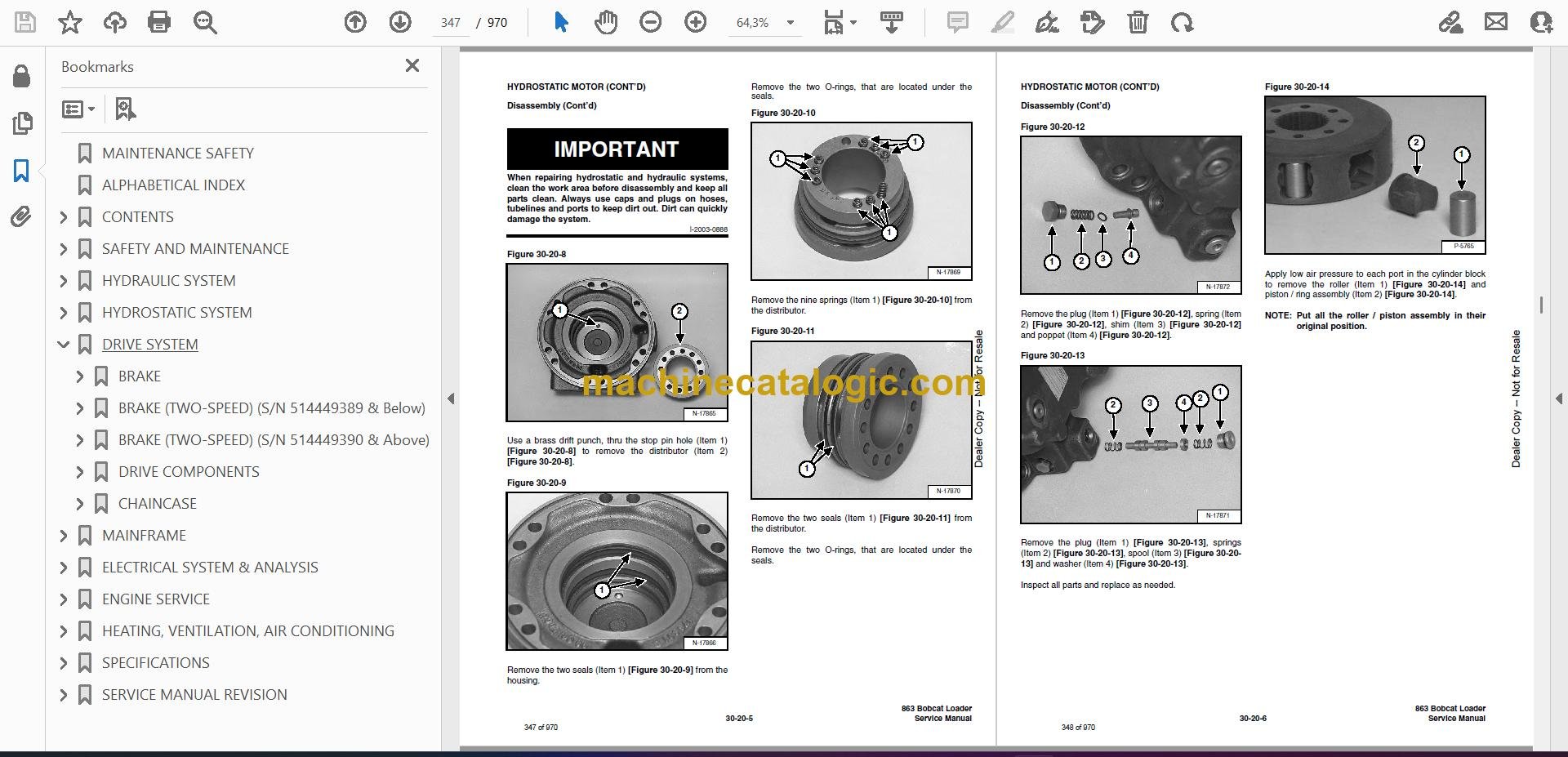
- Disassembly
- Inspection
- Assembly
- Carrier Removal And Installation
- Carrier Parts Identification
- Carrier Disassembly
- Carrier Assembly
- HYDROSTATIC MOTOR (TWO-SPEED)
- Removal And Installation
- Parts Identification
- Disassembly
- Inspection
- Assembly
- CHARGE PRESSURE
- Hydrostatic Charge Pressure Sender Removal And Installation
- HYDROSTATIC PUMP
- Replenishing / High Pressure Relief Valve
- Charge Pressure Relief Valve
- Removal And Installation
- Parts Identification (Right Half)
- Parts Identification (Left Half)
- Hydraulic Pump Removal & Installation
- Disassembly
- Assembly
- DRIVE BELT
- Shield Removal And Installation
- Adjustment
- Replacement
- Tensioner Pulley Removal And Installation
- Tensioner Pulley Tension Spring
- OIL COOLER
- Removal And Installation With STC (Seal Tight Connector)
- DRIVE SYSTEM
- BRAKE
- Pedal Removal And Installation
- Pedal Disassembly And Assembly
- Disc Removal And Installation
- BRAKE (TWO-SPEED) (S/N 514449389 & Below)
- Block Removal And Installation
- Block Disassembly And Assembly
- BRAKE (TWO-SPEED) (S/N 514449390 & Above)
- Block Removal And Installation
- Block Disassembly And Assembly
- DRIVE COMPONENTS
- Axle Seal Removal And Installation
- Axle, Sprocket And Bearings Removal And Installation
- Drive Chain Removal And Installation
- CHAINCASE
- Front Chaincase Cover Removal And Installation
- Rear Chaincase Cover Removal And Installation
- MAINFRAME
- SEAT BAR
- Removal And Installation
- Assembling Components
- Compression Spring Assembly And Assembly
- OPERATOR CAB
- Gas Cylinder Removal And Installation
- Gas Cylinder Bracket Disassembly And Assembly
- Removal And Installation
- OPERATOR SEAT
- Removal And Installation
- Seat Belt Removal And Installation.
- OPERATOR SEAT (SUSPENSION)
- Removal And Installation
- Slide Rail Removal And Installation
- Cushion Removal And Installation
- Back Removal And Installation
- Shock Removal And Installation
- BOB-TACH
- Removal And Installation
- Bob-Tach Lever And Wedge
- Bob-Tach Stops
- Pivot Pin Bushing And Seal Replacement
- POWER BOB-TACH
- Removal And Installation
- Power Bob-Tach Lever And Wedge
- Pivot Pin Bushing And Seal Replacement
- LIFT ARMS
- REAR GRILL
- REAR DOOR
- Removal And Installation (S/N 514449208 & Below)
- Adjusting The Rear Door Latch (S/N 514449208 & Below)
- Striker Removal And Installation (S/N 514449209 & Above)
- Adjusting The Striker (S/N 514449209 & Above)
- Latch Removal And Installation (S/N 514449209 & Above)
- FUEL TANK
- Removal And Installation
- Fuel Level Sender
- CONTROL PEDALS
- Removal And Installation
- Pedal Adjustment
- Crossbar Linkage Removal And Installation
- Lift Foot Pedal Linkage Removal And Installation
- Tilt Foot Pedal Linkage Removal And Installation
- CONTROL PEDALS (ACS)
- Foot Sensor Removal And Installation
- Foot Pedal Removal And Installation
- Foot Pedal Linkage Disassembly And Assembly
- CONTROL PANEL
- CONTROL HANDLE
- Lever Removal And Installation
- Lever Disassembly And Assembly
- Linkage Removal And Installation
- Linkage Neutral Adjustment
- CONTROL HANDLE (ADVANCED HAND CONTROL) (AHC)
- Components Identification
- Trouble shooting Guide
- Parts Identification
- AHC Controller Removal And Installation
- Handle Control Unit Connector
- Control Handle Removal And Installation
- Actuators Disassembly And Assembly
- CONTROL HANDLE (ADVANCED HAND CONTROL) (AHC) (W/ PUSH BUTTON FLOAT)
- Components Identification
- Trouble shooting Guide
- Controller Connector and Wire Identification
- AHC Controller Removal And Installation
- Handle Sensor Removal And Installation
- Handle Sensor Connector
- Control Handle Removal And Installation
- Actuators Disassembly And Assembly
- CONTROL HANDLE (ADVANCED CONTROL SYSTEM) (ACS) ADVANCED HAND CONTROL
- Components Identification
- Handle Sensor Removal And Installation
- Control Handle Removal And Installation
- Control Handle Disassembly and Assembly
- Control Lever Removal And Installation
- Control Lever Boot
- CONTROL HANDLE (ADVANCED CONTROL SYSTEM) (ACS) SELECTABLE HAND / FOOT CONTROL
- Components Identification
- Handle Sensor Removal And Installation
- Control Handle Removal And Installation
- Control Handle Disassembly and Assembly
- Control Lever Removal And Installation
- Control Lever Boot
- ELECTRICAL SYSTEM & ANALYSIS
- ELECTRICAL SCHEMATICS
- ELECTRICAL SYSTEM INFORMATION
- Troubleshooting Chart
- Description
- Fuse Location
- Relay Switches Location
- Solenoid Test
- BATTERY
- Removal And Installation
- Servicing The Electrical System
- Using A Booster Battery (Jump Starting)
- ALTERNATOR (55 AMP)
- Alternator Output Test
- Rectifier (Diode) Test
- Alternator Regulator Test
- Removal And Installation
- Disassembly
- Stator Continuity Test
- Stator Ground Test
- Rotor Continuity Test
- Rotor Ground Test
- Rectifier Continuity (Diode) Test
- Assembly
- ALTERNATOR (90 AMP)
- Adjusting The Alternator Belt
- Alternator Identification
- Charging System Check
- Alternator Voltage Test
- Low Voltage Test
- High Voltage Test
- Removal And Installation
- Rectifier Continuity (Diode) Test
- Alternator Regulator Test
- Disassembly
- Stator Continuity Test
- Stator Ground Test
- Rotor Continuity Test
- Rotor Ground Test
- Assembly
- STARTER (NIPPONDENSO)
- Removal And Installation
- Parts Identification
- Disassembly And Assembly
- External Pinion
- Inspection And Repair
- No Load Test
- STARTER (VALEO)
- Checking
- Removal And Installation
- Parts Identification
- Disassembly and Assembly
- Inspection And Repair
- No Load Test
- INSTRUMENT PANEL
- Left Panel
- Right Panel – Standard Instrument Panel (With Key Switch)
- Right Panel – (Deluxe) (With Keyless Start)
- Right Panel Setup Display Options (Deluxe)
- Deluxe Panel Setup
- Passwords
- Changing The Password
- Option And Field Accessory Panels
- Standard Panel Removal And Installation (Right Side)
- Deluxe Panel Removal And Installation (Right Side)
- Standard & Deluxe Panel Removal And Installation (Left Side)
- LIGHTS
- Front Removal And Installation
- Rear Removal And Installation
- BOBCAT CONTROLLER
- Identification Chart (S/N 514450763 & Below)
- Identification Chart (S/N 514450764 & Above)
- Removal And Installation
- DELUXE INSTRUMENTATION SERVICE CODES
- BICS™ SYSTEM
- Inspecting The BICS™ Controller (Engine STOPPED – Key ON)
- Inspecting Deactivation Of The Auxiliary Hydraulics System (Engine STOPPED – Key ON)
- Inspecting The Seat Bar Sensor (Engine RUNNING)
- Inspecting The Traction Lock (Engine RUNNING)
- Inspecting The Lift Arm Bypass Control
- Additional Inspection For Loaders With Advanced Hand Controls
- Troubleshooting Chart
- Troubleshooting Guide
- SEAT BAR SENSOR
- Troubleshooting Chart
- Test
- Removal And Installation
- BICS™ Circuit Test
- TRACTION LOCK
- Troubleshooting Chart
- Removal And Installation (Single Speed)
- Description Of The Control System (Two-Speed)
- Inspecting The Control System (Two-Speed)
- ADVANCED HAND CONTROL SYSTEM (AHC)
- Components Identification
- Trouble shooting Guide
- Parts Identification
- AHC Controller Removal And Installation
- Handle Control Unit Connector
- Switch Handle Removal And Installation
- Actuators Disassembly And Assembly
- ADVANCED HAND CONTROL SYSTEM (AHC) (W/ PUSH BUTTON FLOAT)
- Components Identification
- Trouble shooting Guide
- Controller Connector and Wire Identification
- AHC Controller Removal And Installation
- Handle Control Unit Removal And Installation
- Handle Control Unit Connector
- Switch Handle Removal And Installation
- Actuators Disassembly And Assembly
- ADVANCED CONTROL SYSTEM (ACS) ADVANCED HAND CONTROL
- Components Identification
- Troubleshooting Guide
- Controller, Connector And Wire Identification
- ACS Controller Removal And Installation
- Handle Sensor Connector
- Switch Handle Removal
- Switch Handle Installation
- Actuators Disassembly and Assembly
- ADVANCED CONTROL SYSTEM (ACS) SELECTABLE HAND / FOOT CONTROL
- Components Identification
- Troubleshooting Guide
- Controller, Connector And Wire Identification
- ACS Controller Removal And Installation
- Handle Sensor Connector
- Switch Handle Removal
- Switch Handle Installation
- Actuators Disassembly and Assembly
- Handle Lock Solenoid Removal And Installation
- Handle Lock Solenoid Disassembly And Assembly
- Handle Lock Solenoid Connector
- Calibration Of The ACS System
- Switchable Hand / Foot Controls Calibration Procedure
- Hand Controls Only Calibration Procedure
- Foot Sensor Disassembly And Assembly
- Foot Sensor Connector
- Foot Lock Solenoid Removal And Installation
- Foot Lock Solenoid Connector
- ELECTRICAL / HYDRAULIC CONTROLS REFERENCE
- Controls Identification Chart
- ENGINE SERVICE
- TROUBLESHOOTING
- ENGINE SPEED CONTROL
- Removal And Installation
- Speed Control Cable
- Speed Control Linkage
- MUFFLER
- AIR CLEANER
- Housing Removal And Installation
- RADIATOR
- Oil Cooler Removal And Installation
- COOLING FAN
- Drive Tension Pulley Removal And Installation
- Gearbox / Blower Housing Removal And Installation
- Blower Removal And Installation
- Gearbox Parts Identification
- Gearbox Disassembly
- Gearbox Assembly
- Gearbox, Checking Backlash
- ENGINE COMPONENTS AND TESTS
- Engine Compression, Checking
- Glow Plug, Checking
- Fuel Shut-Off Solenoid, Checking
- Fuel Shut-Off Solenoid Removal and Installation
- Fuel Injection Pump Removal
- Fuel Injection Pump Timing
- Fuel Injection Pump Installation
- Fuel Injector Removal and Installation
- Fuel Injector, Checking
- Fuel Injector Disassembly
- Fuel Injector Assembly
- Timing Belt Inspection
- Timing Belt Removal
- Timing Belt Installation
- Timing Belt, Replacement In the Loader
- Valve Clearance Adjustment
- Valve Timing, Checking
- Thermostat, Oil Pressure Control Valves And Heater Connections
- ENGINE AND ENGINE MOUNTS
- Removal And Installation
- Engine Mount Replacement
- FLYWHEEL AND HOUSING
- Flywheel Removal And Installation
- Ring Gear Removal And Installation
- Flywheel Housing Removal And Installation
- RPM SENSOR
- RECONDITIONING THE ENGINE
- Deutz Engine Tools Identification Chart
- Disassembly
- Assembly
- Cylinder, Checking
- Camshaft Bearing, Checking
- Camshaft Bearing, Removal And Installation
- Control Rod Guide Bushing Removal
- Control Rod Guide Bushing Installation
- Rear Cover Seal Removal And Installation
- Crankshaft, Checking
- Connecting Rod, Checking
- Piston, Checking
- Piston Pin, Checking
- Piston Rings Installation
- Piston Installation On the Connecting Rod
- Cylinder Head Disassembly
- Valves, Checking
- Valve Seats, Checking
- Valve Spring, Checking
- Cylinder Head Assembly
- Rocker Arm and Bracket, Checking
- Front Cover Disassembly
- Front Cover Assembly
- Turbo Charger Removal and Installation
- Crankshaft Gear Mounting Bolt Torque Procedure
- HEATING, VENTILATION, AIR CONDITIONING
- AIR CONDITIONING SYSTEM FLOW
- COMPONENTS
- SAFETY
- REGULAR MAINTENANCE
- Cleaning The Condenser
- Compressor Drive Belt Inspection
- Filter Elements Removal And Installation
- BASIC TROUBLESHOOTING
- Cleaning The A/C Evaporator Coil & Heater Coil
- Checking The Electrical System
- Compressor Drive Belt Inspection:
- Engine Coolant Bypassing The Heater Valve
- Heater Valve Not Opening Or Closing
- Poor A/C Performance
- GENERAL AIR CONDITIONING SERVICE GUIDELINES
- Compressor Oil
- Compressor Oil Check
- Component Replacement And Refrigeration Leaks
- SYSTEM TROUBLESHOOTING CHART
- Gauge Pressure Related Troubleshooting
- Troubleshooting Tree
- TEMPERATURE / PRESSURE
- AIR CONDITIONING SERVICE
- SYSTEM CHARGING AND RECLAMATION
- Reclamation Procedure
- Charging Procedure With A Manifold Gauge Set
- Charging Procedure
- COMPRESSOR
- Removal And Installation
- Compressor Clutch Disassembly
- CONDENSER
- RECEIVER / DRIER
- PRESSURE RELIEF VALVE
- PRESSURE SWITCH
- EVAPORATOR / HEATER UNIT
- Removal And Installation
- Disassembly And Assembly
- THERMOSTAT
- EXPANSION VALVE
- EVAPORATOR
- HEATER COIL
- Removal And Installation With A/C
- Removal And Installation Without A/C
- HEATER / AC FAN
- Removal And Installation
- Disassembly And Assembly
- Wire Connector Removal And Installation
- HEATER VALVE
- Removal and Installation
- Disassembly And Assembly
- SPECIFICATIONS
- LOADER SPECIFICATIONS
- Loader Dimensions
- Performance
- Controls
- Engine
- Hydraulic System
- Electrical
- Drive System
- Capacities
- Tires
- ENGINE SPECIFICATIONS
- General
- Fuel System
- Valve and Valve Guide and Seat Insert
- Piston and Rings
- Connecting Rod
- Cylinder Head and Block
- Crankshaft and Main Bearings
- Camshaft and Bearings
- Oil Pump
- LOADER TORQUE
- TORQUE SPECIFICATIONS FOR BOLTS
- Torque For General SAE Bolts
- Torque For General Metric Bolts
- HYDRAULIC CONNECTION SPECIFICATIONS
- O-ring Face Seal Connection
- Straight Thread O-ring Fitting
- Tubelines And Hoses
- Flare Fitting
- O-ring Flare Fitting
- Port Seal Fitting
- HYDRAULIC FLUID SPECIFICATIONS
- CONVERSIONS
- Decimal And Millimeter Equivalents
- U.S. To Metric Conversion
- SERVICE MANUAL REVISION
- 863/863H-1
- 863/863H-2
- 863/863H-3
- 863/863H-4
- 863/863H-5
- 863/863H-6
- 863/863H-7
- 863/863H-8
- 863/863H-9
- 863/863H-10
- 863/863H-11
Bobcat Software
Bobcat PDF Manuals


