On a job, a V638 VersaHANDLER is lifting pallets of block, placing trusses, or loading trucks where a skid-steer just can't reach. The people who grab this service manual are the ones who actually have to keep that handler moving: shop mechanics, field techs, and hands-on owners. They're looking for step-by-step repair info, specs, and diagnostic routines so they can fix issues once, not chase them for a week.
What this manual helps you do
- Diagnose hydraulic problems in the boom, outriggers, and auxiliary circuits, and trace them with pressure checks and flow tests
- Troubleshoot drive and steering issues in the telescopic handler drivetrain and axles, including hydrostatic and mechanical components
- Follow teardown and reassembly procedures for cylinders, valves, and other hydraulic components, with seal orientation and inspection points
- Check and set adjustments for boom wear pads, attachment coupler/Bob-Tach type systems, and safety interlocks
- Verify and repair electrical and electronic faults using wiring diagrams, connector locations, and step-by-step test procedures
Who this is for
This is for anyone working on a Bobcat V638 VersaHANDLER TTC within serial range A8HN11001 to A8HN99999 who needs workshop-level repair information. If you only want basic controls, daily checks, or safety instructions, you want the operator's handbook instead, not this manual.
FAQ
Q: Is this a searchable PDF, and can I zoom in on wiring diagrams?
A: These manuals are usually supplied as searchable PDFs, and in my experience the wiring diagrams stay readable when zoomed in on a laptop or tablet.
Q: How do I know it fits my exact machine?
A: Check your serial plate. If your V638 serial number falls between A8HN11001 and A8HN99999, this is the correct service manual series.
Q: I'm just doing routine maintenance, is this overkill?
A: For basic fluids and filters, the operator's handbook or a maintenance chart may be enough. For real troubleshooting or repairs, this service manual is what you want.
Bottom line: If you own or maintain a V638 in that A8HN11001-A8HN99999 serial range and you're doing your own repairs, this is the right manual. If you just want how to drive it, skip this one.
📘 Show Index
Table of Contents:
- CONTENTS
- FOREWORD
- FOREWORD
- SAFETY INSTRUCTIONS
- FIRE PREVENTION
- Maintenance
- Operation
- Electrical
- Hydraulic System
- Fueling
- Starting
- Spark Arrester Exhaust System
- Welding And Grinding
- Fire Extinguishers
- SERIAL NUMBER LOCATION
- VersaHANDLER Serial Number
- Engine Serial Number
- Other Serial Numbers
- DELIVERY REPORT
- BOBCAT VersaHANDLER IDENTIFICATION
- SAFETY & MAINTENANCE
- LIFTING AND BLOCKING THE VERSAHANDLER
- OPERATOR CAB / CANOPY
- TRANSPORTING THE VERSAHANDLER ON A TRAILER
- Loading And Unloading
- Fastening
- TOWING THE VersaHANDLER
- SERVICE SCHEDULE
- AIR CLEANER SERVICE
- Replacing Filter Element(s)
- ENGINE COOLING SYSTEM
- Cleaning The Cooling System
- Checking The Coolant Level
- Replacing The Coolant
- FUEL SYSTEM
- Fuel Specifications
- Filling The Fuel Tank
- Fuel Filter
- ENGINE LUBRICATION SYSTEM
- Checking Engine Oil
- Engine Oil Chart
- Replacing Oil And Filter
- HYDRAULIC / HYDROSTATIC SYSTEM
- Checking And Adding Fluid
- Replacing Hydraulic / Hydrostatic Filter
- Replacing Hydraulic Fluid
- AXLES (FRONT AND REAR)
- Checking Oil Level (Planetary Carrier)
- Draining Oil (Planetary Carrier)
- Checking Oil Level (Rear Differential)
- Draining Oil (Rear Differential)
- Checking Oil Level (Front Differential)
- Draining Oil (Front Differential)
- LUBRICATION
- ATTACHMENT FRAME
- Inspection And Maintenance
- TIRE MAINTENANCE
- Wheel Nuts
- Mounting
- Rotating
- SPARK ARRESTER MUFFLER
- APPROVED BOOM STOP
- Installing The Approved Boom Stop
- Removing The Approved Boom Stop
- ENGINE COVER
- Opening And Closing The Engine Cover
- LATERAL OPERATOR RESTRAINT SYSTEM (LORS)
- System Inspection
- Maintaining
- CHAIN
- Checking And Adjustment Procedure
- Extend / Retract Chain Wear Check
- STOPPING THE ENGINE AND LEAVING THE VERSAHANDLER
- VersaHANDLER STORAGE AND RETURN TO SERVICE
- Storage
- Return To Service
- EMERGENCY EXIT
- HYDRAULIC SYSTEM
- HYDRAULIC / HYDROSTATIC SCHEMATICS
- HYDRAULIC SYSTEM INFORMATION
- Glossary Of Hydraulic / Hydrostatic Symbols
- Troubleshooting Chart
- Tightening Procedures
- LIFT CYLINDER
- Removal And Installation
- Parts Identification
- Disassembly
- Assembly
- BUCKET POSITION CYLINDER
- Removal And Installation
- Removal And Installation (Cont’d)
- Parts Identification
- Disassembly
- Assembly
- EXTENSION CYLINDER
- Cylinder Group Removal And Installation
- Parts Identification
- Disassembly
- Assembly
- TILT CYLINDER
- Removal And Installation
- Parts Identification
- Disassembly
- Assembly
- STEERING CYLINDER (FRONT)
- Removal
- Installation
- Disassembly
- Assembly
- STEERING CYLINDER (REAR)
- Removal
- Installation
- Disassembly
- Assembly
- DRIVE BOX
- Parts Identification
- Disassembly
- Assembly
- Special Tools
- MAIN RELIEF VALVE
- Testing And Adjustment
- Removal And Installation
- QUICK-TACH CYLINDER
- Removal And Installation
- Parts Identification
- Disassembly
- Assembly
- FRAME LEVELING CYLINDER
- Removal And Installation
- Parts Identification
- Disassembly
- Assembly
- STEERING MODE VALVE BLOCK
- Removal And Installation
- Parts Identification
- Disassembly
- Solenoid Testing
- Assembly
- BRAKE VALVE
- Removal And Installation
- Disassembly And Assembly
- GEAR PUMP
- Removal And Installation
- Parts Identification
- Disassembly And Assembly
- FAN MOTOR
- Removal And Installation
- Parts Identification
- Disassembly And Assembly
- HYDRAULIC RESERVOIR
- STEERING VALVE
- Removal And Installation
- Parts Identification
- Disassembly
- Inspection
- Assembly
- HYDRAULIC CONTROL VALVE
- Troubleshooting Chart (Controllers)
- Telescoping Valve Section Troubleshooting
- Auxiliary Valve Section Troubleshooting
- Troubleshooting Chart (Control Valve)
- Removal And Installation
- Parts Identification
- Disassembly And Assembly
- End Housing Disassembly And Assembly
- Lifting Valve Section Disassembly And Assembly
- Tilting Valve Section Disassembly And Assembly
- Telescoping Valve Section Disassembly And Assembly
- Auxiliary / Frame Leveling Valve Section Disassembly And Assembly
- Inlet-Outlet Valve Section Disassembly And Assembly
- PORT RELIEF VALVES
- FLOW CONTROL VALVE
- JOYSTICK
- PARKING BRAKE
- Pressure Switch Removal And Installation
- Pressure Switch Disassembly And Assembly
- Parking Brake Valve Removal And Installation
- Parking Brake Valve Disassembly And Assembly
- PRESSURE REDUCING VALVE
- Testing
- Removal And Installation
- Disassembly And Assembly
- ACCUMULATOR
- TOW VALVE
- Removal And Installation
- Disassembly And Assembly
- STABILIZER CYLINDER
- Removal
- Parts Identification
- Disassembly
- Assembly
- Installation
- STABILIZER CONTROL VALVE
- Parts Identification
- Removal
- Installation
- HYDROSTATIC SYSTEM
- HYDROSTATIC SYSTEM INFORMATION
- Troubleshooting Chart
- Replenishing Valve Function
- OIL COOLER
- HYDROSTATIC DRIVE MOTOR
- Removal And Installation
- Parts Identification
- Disassembly
- Inspection
- Assembly
- HYDROSTATIC PUMP
- Removal And Installation
- Parts Identification
- Disassembly
- Inspection
- Assembly
- DRIVE SYSTEM
- TROUBLESHOOTING
- AXLE AND DIFFERENTIAL (FRONT)
- General Information
- Planetary Carrier Parts Identification
- Planetary Carrier Disassembly
- Steering Knuckle And Drive Axle Parts Identification
- Steering Knuckle Disassembly
- Drive Axle Disassembly
- Brake System Parts Identification
- Brake System Disassembly
- Differential Parts Identification
- Differential Disassembly
- Bevel Pinion Parts Identification
- Bevel Pinion Disassembly
- Bevel Pinion Assembly
- Differential Assembly
- Brake System Assembly
- Drive Axle Assembly
- Steering Knuckle Assembly
- Planetary Carrier Assembly
- Special Tools
- AXLE AND DIFFERENTIAL (REAR)
- General Information
- Planetary Carrier Parts Identification
- Steering Knuckle And Drive Axle Parts Identification
- Steering Knuckle Disassembly
- Differential And Bevel Pinion Parts Identification
- Differential Disassembly
- Bevel Pinion Disassembly
- Bevel Pinion Assembly
- Differential Assembly
- Steering Knuckle Assembly
- Planetary Carrier Assembly
- Special Tools
- FRONT AXLE
- AXLE TOE-IN
- PARKING BRAKE
- Releasing The Brake For Towing
- Re-Activating The Brake
- STEERING ANGLE ADJUSTMENT
- DRIVE SHAFT
- SERVICE BRAKE
- Description
- Bleeding The Brake Circuit
- REAR AXLE
- MAINFRAME
- OPERATOR CAB (S/N A8HM12999 & BELOW)
- OPERATOR CAB (S/N A8HM13000 & ABOVE)
- CANOPY
- OPERATOR SEAT
- FIXED BOOM
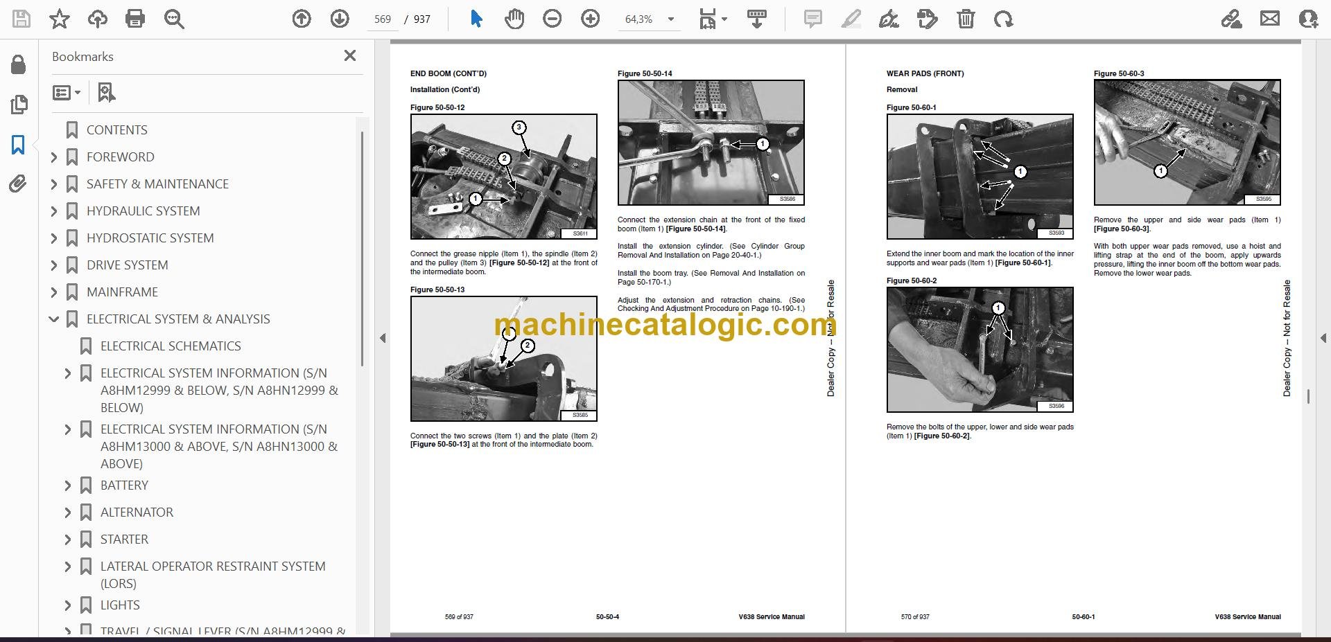
- END BOOM
- WEAR PADS (FRONT)
- WEAR PADS (REAR)
- ENGINE COVER
- Gas Cylinder Removal And Installation
- Removal And Installation
- AIR INTAKE COWLING
- FUEL TANK
- QUICK-TACH
- REAR WEIGHTS
- FENDER
- PIVOT LINK
- DASH COVER / STEERING COLUMN COVER (S/N A8HM12999 & BELOW, S/N A8HN12999 & BELOW)
- DASH COVER / STEERING COLUMN COVER (S/N A8HM13000 & ABOVE, S/N A8HN13000 & ABOVE)
- JOYSTICK PANEL (S/N A8HM12999 & BELOW, S/N A8HN12999 & BELOW)
- JOYSTICK PANEL (S/N A8HM13000 & ABOVE, S/N A8HN13000 & ABOVE)
- INTERMEDIATE BOOM
- BOOM TRAY
- STABILIZER FRAME
- ELECTRICAL SYSTEM & ANALYSIS
- ELECTRICAL SCHEMATICS
- ELECTRICAL SYSTEM INFORMATION (S/N A8HM12999 & BELOW, S/N A8HN12999 & BELOW)
- Troubleshooting Chart
- Description
- Fuses, Diodes And Relays
- ELECTRICAL SYSTEM INFORMATION (S/N A8HM13000 & ABOVE, S/N A8HN13000 & ABOVE)
- Troubleshooting Chart
- Description
- Fuses, Diodes And Relays
- BATTERY
- Removal And Installation
- Servicing
- Using A Booster Battery (Jump Starting)
- ALTERNATOR
- Removal And Installation
- Adjusting The Alternator Belt
- STARTER
- Removal And Installation
- Parts Identification
- Disassembly
- Inspection And Repair
- Assembly
- LATERAL OPERATOR RESTRAINT SYSTEM (LORS)
- Restraint Bar Removal And Installation
- Sensor Removal And Installation
- Strut Removal And Installation
- Strut Disassembly And Assembly
- Restraint Bar Bushing Removal And Installation
- Restraint Bar Bumper Removal And Installation
- LIGHTS
- Rear Light Removal And Installation
- Front Light Removal And Installation
- TRAVEL / SIGNAL LEVER (S/N A8HM12999 & BELOW, S/N A8HN12999 & BELOW)
- TRAVEL / SIGNAL LEVER (S/N A8HM13000 & ABOVE, S/N A8HN13000 & ABOVE)
- INSTRUMENT PANEL
- SWITCH PANEL (S/N A8HM12999 & BELOW, S/N A8HN12999 & BELOW)
- Removal And Installation
- Parts Identification
- SWITCH PANEL (S/N A8HM13000 & ABOVE, S/N A8HN13000 & ABOVE)
- Removal And Installation
- Parts Identification
- BRAKE LIGHT SWITCH
- Removal And Installation
- Adjustment
- WIPER MOTOR (FRONT)
- WIPER MOTOR (TOP)
- WIPER MOTOR (REAR)
- PEDAL ASSEMBLY
- Removal And Installation
- Disassembly And Assembly
- INCHING SWITCH
- Removal And Installation
- Adjustment
- SERVICE SOFTWARE
- Connecting The Laptop Computer
- Entering The Service Software
- Monitor Screen
- Warnings Screen
- Calibrate Inch Pedal
- Calibrate Creep Potentiometer
- Program / Update Susmic Controller
- FRAME LEVEL SPEED SWITCH
- Description
- Removal
- Installation
- ENGINE SERVICE
- TROUBLESHOOTING
- ENGINE SPEED CONTROL
- MUFFLER
- AIR CLEANER
- Housing Removal And Installation
- OIL COOLER / RADIATOR
- Removal And Installation
- Disassembly And Assembly
- ENGINE AND ENGINE MOUNTS
- ENGINE COMPONENTS AND TESTING
- Fuel Injection Pump Removal
- Fuel Injection Pump Installation
- Fuel Injector Removal And Installation
- Checking The Fuel Lift Pump
- Fuel Lift Pump Removal And Installation
- Compression Checking
- Glow Plug Checking
- Glow Plugs Removal And Installation
- ENGINE TIMING
- ENGINE / HYDROSTAT ASSEMBLY
- FLYWHEEL AND HOUSING
- Removal And Installation
- Ring Gear Removal
- Ring Gear Installation
- RECONDITIONING THE ENGINE
- Turbocharger Troubleshooting
- Turbocharger Description
- Turbocharger Removal And Installation
- Exhaust Manifold Removal And Installation
- Fuel Injector Cover Removal And Installation
- Rocker Cover Removal And Installation
- Cylinder Head Removal
- Cylinder Head Inspection
- Cylinder Head Installation
- Rocker Shaft Disassembly And Assembly
- Valve Removal
- Valve Springs Checking
- Valve Depth Checking
- Valve Guides Checking
- Valve Guide Removal
- Valve Guide Installation
- Valves Checking
- Cutting A Valve Seat
- Valve Seat Assembly
- Changing Valve Springs (With Cylinder Head Installed)
- Valve Clearance Adjustment
- Timing Case And Drive Assembly Description
- Timing Cover Removal
- Timing Cover Installation
- Crankshaft Pulley Removal And Installation
- Front Oil Seal Removal And Installation
- Timing Case And Gear Removal
- Timing Case And Gear Installation
- Camshaft And Tappets Removal
- Camshaft And Tappets Installation
- Pistons And Connecting Rods Description
- Pistons And Connecting Rods Removal
- Pistons And Connecting Rods Disassembly
- Piston Ring End Gap
- Piston Ring Installation
- Piston Ring Groove Clearance
- Connecting Rod Inspection
- Connecting Rod Bushing Replacement
- Piston And Connecting Rod Assembly
- Piston And Connecting Rod Installation
- Checking Piston Height
- Crankshaft And Bearings Description
- Crankshaft And Bearings Removal
- Inspection Of Crankshaft And Bearings
- Crankshaft And Bearings Installation
- Rear Oil Seal Removal
- Rear Oil Seal Housing Positioning
- Rear Oil Seal Installation
- Checking Crankshaft End Play
- Cooling System Description
- Thermostat Removal and Installation
- Thermostat Testing
- Lubricating Oil Cooler Removal And Installation
- Water Pump Removal
- Water Pump Installation
- Engine Lubrication System Description
- Oil Filter Adapter Removal And Installation
- Oil Pan Removal And Installation
- Oil Screen And Pick-up Tube
- Oil Pump Removal
- Oil Pump Installation
- Oil Pump Disassembly And Assembly
- Oil Pressure Relief Valve Disassembly And Assembly
- Engine Block Description
- Engine Block Disassembly And Assembly
- Piston Cooling Jet Removal
- Piston Cooling Jet Installation
- Piston Cooling Jet Alignment
- Inspection
- Cylinder Liner Inspection
- Cylinder Liner Removal
- Cylinder Liner Installation
- HEATING, VENTILATION AND AIR CONDITIONING (HVAC)
- AIR CONDITIONING SYSTEM FLOW
- COMPONENTS
- SAFETY
- REGULAR MAINTENANCE
- Filter Element Removal And Installation
- Compressor Drive Belt Inspection
- Cleaning The Condenser
- BASIC TROUBLESHOOTING
- Poor A/C Performance
- Compressor Drive Belt Inspection
- Checking The Electrical System
- GENERAL AIR CONDITIONING SERVICE GUIDELINES
- Compressor Oil
- Compressor Oil Check
- Component Replacement And Refrigeration Leaks
- SYSTEM TROUBLESHOOTING
- Chart
- Gauge Pressure Related Troubleshooting
- TEMPERATURE / PRESSURE
- AIR CONDITIONING SERVICE
- SYSTEM CHARGING AND RECLAMATION
- Reclamation Procedure
- Charging Procedure With A Manifold Gauge Set
- Charging Procedure
- COMPRESSOR
- Removal And Installation
- Compressor Clutch Disassembly And Assembly
- CONDENSER (S/N A8HM12999 & BELOW)
- CONDENSER (S/N A8HM13000 & ABOVE)
- RECEIVER / DRIER
- PRESSURE SWITCH
- EVAPORATOR / BLOWER UNIT (S/N A8HM12999 & BELOW)
- EVAPORATOR / BLOWER / HEATER UNIT (S/N A8HM13000 & ABOVE)
- EXPANSION VALVE (S/N A8HM12999 & BELOW)
- EXPANSION VALVE (S/N A8HM13000 & ABOVE)
- HEATER ASSEMBLY
- Removal And Installation
- Fan Removal And Installation
- Core Removal And Installation
- SPECIFICATIONS
- VERSAHANDLER SPECIFICATIONS
- Machine Dimensions
- Performance Specifications
- Engine
- Controls
- Drive System
- Tires
- Capacities
- Hydraulic System
- Electrical
- Instrument Panel
- ENGINE SPECIFICATIONS
- General
- Cylinder Head
- Valve Guides
- Exhaust Valves
- Intake Valves
- Valve Springs
- Rocker Shaft, Rockers And Bushings
- Pistons And Piston Rings
- Connecting Rods And Bearings
- Crankshaft
- Crankshaft Re-Grind Data
- Main Bearings
- Thrust Washers
- Camshaft And Thrust Washer
- Cylinder Block
- Cylinder Liners
- Fuel Injection Pump
- Fuel Injectors
- Fuel Lift Pump
- Timing Case And Timing Gears
- Oil Pump, Gear And Relief Valve
- Turbocharger
- Flywheel
- Water Pump And Thermostat
- Engine Torque Component
- MACHINE TORQUE SPECIFICATIONS
- Axle
- Boom
- Drive Box
- Drive Motor
- Engine
- Hydraulic Pump
- TORQUE SPECIFICATIONS FOR BOLTS
- Torque for General SAE Bolts
- Torque For General Metric Bolts
- HYDRAULIC CONNECTION SPECIFICATIONS
- O-ring Face Seal Connection
- Straight Thread O-ring Fitting
- Tubelines And Hoses
- Port Seal Fitting
- HYDRAULIC / HYDROSTATIC FLUID SPECIFICATIONS
- CONVERSIONS
- Decimal And Millimeter Equivalent Chart
- U.S. To Metric Conversion Chart
- ALPHABETICAL INDEX
- SERVICE MANUAL REVISION
Bobcat Software
Bobcat PDF Manuals


