The Bobcat 864 is a mid-size skid-steer-class loader that lives on pallets, dirt, and concrete all day. Around my yard, this is the kind of machine that's always either loading trucks or feeding attachments, so downtime hurts. People grab the service manual when they're past warranty and need real repair info, not safety stickers and fluid charts. They want torque specs, test ports, wiring colors, and step-by-step teardown so the machine goes back out clean and on time.
What this manual helps you do
- Diagnose drive and travel issues by checking hydrostatic and charge pressures with test ports and gauges
- Trace and repair electrical faults using wiring diagrams for this exact serial range
- Follow step-by-step removal and installation for pumps, drive motors, axles, and major hydraulic components
- Rebuild and reseal cylinders, valves, and Bob-Tach related hydraulics with proper disassembly and reassembly order
- Set and verify adjustments on linkages, controls, and engine-related components after repair
Who this is for
This manual is for anyone maintaining or repairing a Bobcat 864 loader in the serial range 518911001 through 518914999: small contractors, rental fleets, shop mechanics, and owner-operators who turn their own wrenches. If you only need basic operating instructions or daily checks, you want the operator's handbook instead, not this service manual.
FAQ
Q: Is this a searchable PDF, and are the wiring diagrams readable?
A: These manuals are usually scanned or native PDFs that you can search, and the wiring diagrams are laid out so you can zoom in and read pin numbers and wire colors.
Q: How do I know if it covers my exact 864?
A: Check your loader's serial plate. If it falls between 518911001 and 518914999, this is the right manual. If it doesn't, you need a different book.
Q: Is this the right document if I'm doing engine or hydraulic rebuild work?
A: Yes. This is the workshop-level service manual, which is what you want for teardown, inspection, testing, and reassembly.
Bottom line: If your 864's serial number is in that range and you're doing real repair work, this is the right manual. If your serial is outside that range, skip it.
📘 Show Index
Table of Contents:
- MAINTENANCE SAFETY
- ALPHABETICAL INDEX
- CONTENTS
- FOREWORD
- SAFETY INSTRUCTIONS
- FIRE PREVENTION
- Maintenance
- Operation
- Electrical
- Hydraulic System
- Fueling
- Starting
- Spark Arrestor Exhaust System
- Welding And Grinding
- Fire Extinguishers
- SERIAL NUMBER LOCATIONS
- Loader Serial Number
- Engine Serial Number
- DELIVERY REPORT
- BOBCAT LOADER IDENTIFICATION
- SAFETY AND MAINTENANCE
- LIFTING AND BLOCKING THE LOADER
- LIFT ARM SUPPORT DEVICE
- Engaging The Lift Arm Support Device
- Disengaging The Lift Arm Support Device
- OPERATOR CAB
- Raising The Operator Cab
- Lowering The Operator Cab
- Emergency Exit
- TRANSPORTING THE BOBCAT LOADER
- TOWING THE LOADER
- REMOTE START
- Procedure For Loader Without Attachments Control Harness
- Procedure For Loader With Attachments Control Harness
- SERVICE SCHEDULE
- AIR CLEANER SERVICE
- ENGINE COOLING SYSTEM
- Cleaning The Cooling System
- FUEL SYSTEM
- Fuel Specifications
- Filling The Fuel Tank
- Fuel Filter
- Removing Air From The Fuel System
- ENGINE LUBRICATION SYSTEM
- Checking Engine Oil
- Replacing Oil And Filter
- HYDRAULIC/HYDROSTATIC SYSTEM
- Checking And Adding Fluid
- Hydraulic/Hydrostatic Filter Replacement
- Replacing Hydraulic Fluid
- FAN GEARBOX
- BOB-TACH
- Inspection And Maintenance
- POWER BOB-TACH (OPTION)
- Inspection And Maintenance
- LUBRICATING THE LOADER
- HYDRAULIC SYSTEM
- HYDRAULIC / HYDROSTATIC SCHEMATICS
- HYDRAULIC SYSTEM INFORMATION
- Glossary Of Hydraulic/Hydrostatic Symbols For Loaders
- Troubleshooting
- Tighten Procedures
- CYLINDER (LIFT)
- Checking
- Removal And Installation
- Parts Identification
- Disassembly
- Assembly
- CYLINDER (TILT)
- Checking
- Removal And Installation
- Rod End Seal
- Parts Identification
- Disassembly
- Assembly
- CYLINDER (POWER BOB-TACH)
- Checking
- Removal And Installation
- Parts Identification
- Disassembly
- Assembly
- MAIN RELIEF VALVE (FOOT CONTROL)
- Checking The Main Relief Valve At Front Auxiliary Hydraulics
- Checking The Main Relief Valve Without Front Auxiliaries
- Removal And Installation
- Adjustment
- MAIN RELIEF VALVE (AHC)
- Checking The Main Relief Valve At Front Auxiliary Hydraulics
- Checking The Main Relief Valve Without Front Auxiliaries
- Removal and Installation
- Adjustment
- HYDRAULIC CONTROL VALVE (FOOT CONTROL)
- Removal And Installation
- BICS™ Valve, Removal And Installation
- BICS™ Valve, Lift Arm Bypass Orifice Disassembly And Assembly
- BICS™ Valve, Check Valve Disassembly And Assembly
- BICS™ Valve, Lock Valve Disassembly And Assembly
- BICS™ Valve, Solenoid Disassembly And Assembly
- BICS™ Valve, Solenoid Testing
- Identification Chart
- Load Check Valve
- Main Relief Valve
- Port Relief Valve, Tilt Spool (Linkage End)
- Port Relief Valve, Lift Spool (Bonnet End)
- Anti-Cavitation Valve/Port Relief Valve, Tilt Spool (Bonnet End)
- Anti-Cavitation Valve, Lift Spool (Linkage End)
- Rubber Boot
- Lift And Tilt Lock Block
- Lift Spool and Detent
- Tilt Spool Removal And Installation
- Auxiliary Spool Removal And Installation (Bonnet End)
- Auxiliary Spool Removal And Installation (Linkage End)
- Auxiliary Plug Removal And Installation
- Auxiliary Electric Solenoid Disassembly
- Port Relief-Auxiliary Section Disassembly
- Cleaning And Inspection
- HYDRAULIC CONTROL VALVE (ADVANCE HAND
- CONTROL) (AHC), ADVANCE CONTROL SYSTEM (ACS)
- Actuator Removal And Installation (In Loader)
- Removal And Installation
- Actuator Removal And Installation (Out Of Loader)
- BICS™ Valve, Removal And Installation
- BICS™ Valve, Lift Arm Bypass Orifice Disassembly And Assembly
- BICS™ Valve, Check Valve Disassembly And Assembly
- BICS™ Valve, Lock Valve Disassembly And Assembly
- BICS™ Valve, Solenoid Disassembly And Assembly
- BICS™ Valve, Solenoid Testing
- Identification Chart
- Identification Chart
- Lift Base End Restrictor
- Load Check Valve
- Main Relief Valve
- Port Relief Valve
- Anti-Cavitation Valve/Port Relief Valve
- Anti-Cavitation Valve
- Lift Spool Removal
- Lift Spool Removal And Installation
- Lift and Tilt Spool Disassembly And Assembly
- Auxiliary Spool Removal And Installation
- Auxiliary Electric Solenoid Disassembly
- Port-Auxiliary Section Disassembly
- Cleaning And Inspection
- LIFT ARM BYPASS CONTROL VALVE
- Inspecting
- Additional Inspection For Loaders With Advanced Hand Controls
- Removal And Installation
- Disassembly And Assembly
- HYDRAULIC PUMP (SINGLE GEAR)
- Checking The Output Of The Pump
- Removal And Installation
- Parts Identification
- Disassembly
- Inspection
- Assembly
- HYDRAULIC PUMP (HI-FLOW)
- Checking The Output Of The High Flow Pump
- Removal And Installation
- Parts Identification
- Disassembly
- Inspection
- Assembly
- HYDRAULIC/HYDROSTATIC FILTER
- Housing Removal And Installation
- Mount Removal And Installation
- HYDRAULIC FLUID RESERVOIR
- Draining The Hydraulic Fluid Reservoir
- Removal And Installation
- Hydraulic Fluid Screen
- CONTROLS
- Control Pedal Removal And Installation
- Control Pedal Adjustment
- Crossbar Linkage Removal And Installation
- Crossbar Linkage Inspection
- Control Foot Sensor (ACS) Removal And Installation
- Control Pedal (ACS) Removal And Installation
- Control Pedal Linkage (ACS) Disassembly And Assembly
- BUCKET POSITION VALVE
- Solenoid Removal And Installation
- Solenoid Testing
- Removal And Installation
- Disassembly And Assembly
- REAR AUXILIARY DIVERTER
- Disassembly
- Inspection
- Solenoid Testing
- Assembly
- SELECT VALVE
- Checking The High Flow Pump Relief Valve
- Removal And Installation
- Disassembly And Assembly
- Solenoid Testing
- REAR AUXILIARY DIVERTER VALVE (SINGLE SHUTTLE)
- Removal And Installation
- Disassembly
- Inspection
- Solenoid Testing
- Assembly
- POWER BOB-TACH BLOCK
- Removal And Installation
- Disassembly And Assembly
- AUXILIARY PRESSURE RELEASE (ACCUMULATOR)
- Removal and Installation
- Disassembly And Assembly
- HYDROSTATIC SYSTEM
- HYDROSTATIC SYSTEM INFORMATION
- Troubleshooting Chart
- Replenishing Valve Function
- CONTROL PANEL
- STEERING
- Lever Removal And Installation
- Lever Disassembly And Assembly
- Linkage Removal And Installation
- Linkage Neutral Adjustment
- STEERING (ADVANCED HAND CONTROL) (AHC)
- Components Identification
- Handle Control Unit Removal And Installation
- Switch Handle Removal And Installation
- Handle Removal And Installation
- Handle Disassembly And Assembly
- Steering Lever Removal And Installation
- Steering Lever Boot
- STEERING (ADVANCED HAND CONTROL) (AHC) W/ PUSH BUTTON FLOAT
- Components Identification
- Handle Sensor Removal And Installation
- Control Handle Removal and Installation
- Control Handle Disassembly and Assembly
- Control Lever Removal and Installation
- Control Lever Boot
- STEERING (ADVANCED CONTROL SYSTEM) (ACS)
- Components Identification
- Handle Sensor Removal And Installation
- Control Handle Removal and Installation
- Control Handle Disassembly and Assembly
- Control Lever Removal and Installation
- Control Lever Boot
- HYDROSTATIC MOTOR
- Removal And Installation
- Parts Identification
- Disassembly
- Inspection
- Assembly
- Filling
- CHARGE PRESSURE SENDER
- HYDROSTATIC PUMP
- Removal And Installation
- Replenishing/High Pressure Relief Valve(s)
- Charge Pressure Relief Valve
- Parts Identification (Right Half)
- Parts Identification (Left Half)
- Hydraulic Pump Removal And Installation
- Disassembly
- Assembly
- DRIVE BELT
- Shield Removal And Installation
- Adjustment
- Replacement
- Tensioner Pulley Removal And Installation
- Tensioner Pulley Disassembly And Assembly
- Tensioner Pulley Tension Spring
- OIL COOLER
- Removal and Installation
- Removal And Installation With STC (Seal Tight Connector)
- DRIVE SYSTEM
- BRAKE
- Pedal Removal And Installation
- Pedal Disassembly And Assembly
- Switch Operated Parking Brake
- Block Removal And Installation
- Block Disassembly And Assembly
- Traction Lock Bypass Knob
- DRIVE COMPONENTS
- Track Checking
- Track Adjustment
- Track Removal And Installation
- Track Idler (Front) Removal And Installation
- Track Idler (Front) Parts Identification
- Track Idler (Front) Disassembly
- Track Idler (Front) Assembly
- Track Idler (Rear) Removal And Installation
- Track Idler (Rear) Parts Identification
- Track Idler (Rear) Disassembly
- Track Idler (Rear) Assembly
- Track Roller Removal And Installation
- Track Roller Parts Identification
- Track Roller Disassembly
- Track Roller Assembly
- Track Housing Removal And Installation
- Track Damage Identification
- MAINFRAME
- SEAT BAR
- Removal And Installation
- Assembling Components
- Compression Spring Disassembly And Assembly
- OPERATOR CAB
- Gas Cylinder Removal And Installation
- Gas Cylinder Disassembly And Assembly
- Removal And Installation
- OPERATOR SEAT
- Removal And Installation
- Seat Belt Removal And Installation
- OPERATOR SEAT (SUSPENSION)
- Removal And Installation
- Slide Rail Removal And Installation
- Cushion Removal And Installation
- Back Removal And Installation
- Shock Removal And Installation
- BOB-TACH
- Inspection And Maintenance
- Bob-Tach Lever And Wedge
- Removal And Installation
- Pivot Pin Bushing And Seal Replacement
- POWER BOB-TACH
- Inspection And Maintenance
- Power Bob-Tach Lever And Wedge
- Removal And Installation
- Pivot Pin Bushing And Seal Replacement
- LIFT ARMS
- REAR GRILL
- REAR DOOR
- Removal And Installation
- Adjusting The Rear Door Latch
- FUEL TANK
- Removal And Installation
- Fuel Level Sender
- Fuel Pick-up Screen/Check Valve
- ELECTRICAL SYSTEM & ANALYSIS
- ELECTRICAL SCHEMATICS
- ELECTRICAL SYSTEM INFORMATION
- Troubleshooting Chart
- Description
- Fuse Location
- Relay Switch Location
- Solenoid Test
- BATTERY
- Removal And Installation
- Servicing The Battery
- Using A Booster Battery
- ALTERNATOR (55 AMP)
- Adjusting The Alternator Belt
- Alternator Output Test
- Rectifier (Diode) Test
- Alternator Regulator Test
- Removal And Installation
- Disassembly
- Stator Continuity Test
- Stator Ground Test
- Rotor Continuity Test
- Rotor Ground Test
- Rectifier Continuity (Diode) Test
- Assembly
- ALTERNATOR (90 AMP)
- Adjusting The Alternator Belt
- Alternator Identification
- Charging System Check
- Alternator Voltage Test
- Low Voltage Test
- High Voltage Test
- Removal And Installation
- Rectifier Continuity (Diode) Test
- Alternator Regulator Test
- Disassembly
- Stator Continuity Test
- Stator Ground Test
- Rotor Continuity Test
- Rotor Ground Test
- Assembly
- STARTER
- Removal And Installation
- Parts Identification
- Disassembly And Assembly
- External Pinion
- Inspection And Repair
- No Load Test
- INSTRUMENT PANEL
- Left Panel (Standard)
- Right Panel-Standard Instrument Panel (With Key Switch) [Figure 60-50-2]
- Right Panel (Deluxe) (With Keyless Start) [Figure 60- 50-3]
- Right Panel Setup Display Options (Deluxe)
- Passwords
- Option And Field Accessory Panels
- Standard Panel Removal And Installation (Right Side)
- Deluxe Panel Removal And Installation (Right Side)
- Standard And Deluxe Panel Removal And Installation (Left Side)
- Front Accessory Panel Removal And Installation
- LIGHTS
- Front Removal And Installation
- Rear Removal And Installation
- BOBCAT CONTROLLER
- Identification Chart
- Removal And Installation
- DIAGNOSTICS SERVICE CODES
- BICS™ SYSTEM
- Inspecting The BICS™ Controller (Engine STOPPED – Key ON)
- Inspecting Deactivation Of The Auxiliary Hydraulics System (Engine STOPPED – Key ON)
- Inspecting The Seat Bar Sensor (Engine RUNNING)
- Inspecting The Traction Lock (Engine RUNNING)
- Inspecting The Lift Arm Bypass Control
- Additional Inspection For Loaders With Advanced Hand Controls (AHC)
- Troubleshooting Chart
- Troubleshooting Guide
- SEAT BAR SENSOR
- Troubleshooting Chart
- Test
- Removal And Installation
- BICS™ Circuit Test
- TRACTION LOCK
- Description Of The Control System
- Inspecting The Control System
- Parking Brake Solenoid Removal And Installation
- Traction Lock Bypass Knob
- ADVANCE HAND CONTROL (AHC) SYSTEM
- Components Identification
- Troubleshooting Guide
- Parts Identification
- AHC Controller Removal And Installation
- Handle Control Unit Connector
- Switch Handle Removal and Installation
- Actuators Disassembly and Assembly
- ADVANCED HAND CONTROL (AHC) SYSTEM (W/ PUSH BUTTON FLOAT) (CONT’D)
- Components Identification
- Troubleshooting Guide
- Controller Connector And Wire Identification
- AHC Controller Removal And Installation
- Handle Sensor Removal And Installation
- Handle Sensor Connector
- Switch Handle Removal and Installation
- Actuators Disassembly and Assembly
- ADVANCED CONTROL SYSTEM (ACS)
- Components Identification
- Troubleshooting Guide
- Controller, Connector And Wire Identification
- ACS Controller Removal And Installation
- Handle Sensor Connector
- Switch Handle Removal
- Switch Handle Installation
- Actuators Disassembly and Assembly
- Handle Lock Solenoid Removal And Installation
- Handle Lock Solenoid Disassembly And Assembly
- Handle Lock Solenoid Connector
- Calibration Of The ACS System
- Switchable Hand/Foot Controls Calibration Procedure
- Hand Controls Only Calibration Procedure
- Foot Sensor Disassembly And Assembly
- Foot Sensor Connector
- Foot Lock Solenoid Removal And Installation
- Foot Lock Solenoid Connector
- ELECTRICAL/HYDRAULIC CONTROLS REFERENCE
- Controls Identification Chart
- ENGINE SERVICE
- TROUBLESHOOTING
- ENGINE SPEED CONTROL
- Removal And Installation
- Speed Control Cable
- Speed Control Linkage
- MUFFLER
- AIR CLEANER
- Housing Removal And Installation
- RADIATOR
- Oil Cooler Removal And Installation
- COOLING FAN
- Drive Tension Pulley Removal And Installation
- Gearbox/Blower Housing Removal And Installation
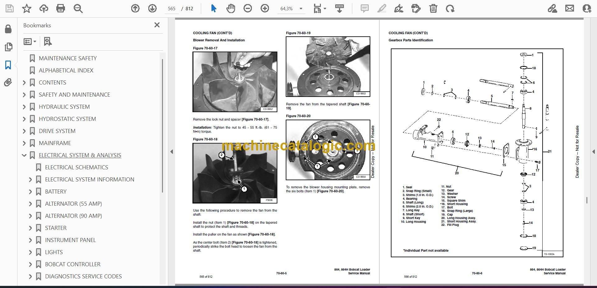
- Blower Removal And Installation
- Gearbox Parts Identification
- Gearbox Disassembly
- Gearbox Assembly
- Gearbox, Checking Backlash
- ENGINE COMPONENTS AND TESTS
- Engine Compression, Checking
- Glow Plug, Checking
- Fuel Shut-Off Solenoid, Checking
- Fuel Shut-Off Solenoid Removal and Installation
- Fuel Injection Pump Removal
- Fuel Injection Pump Timing
- Fuel Injection Pump Installation
- Fuel Injector Removal and Installation
- Fuel Injector, Checking
- Fuel Injector Disassembly
- Fuel Injector Assembly
- Timing Belt Inspection
- Timing Belt Removal
- Timing Belt Installation
- Timing Belt, Replacement In the Loader
- Valve Clearance Adjustment
- Valve Timing, Checking
- Thermostat, Oil Pressure Control Valves And Heater Connections
- ENGINE AND ENGINE MOUNTS
- Removal And Installation
- Engine Mount Replacement
- FLYWHEEL AND HOUSING
- Flywheel Removal And Installation
- Ring Gear Removal And Installation
- Flywheel Housing Removal And Installation
- RECONDITIONING THE ENGINE
- Deutz Engine Tools Identification Chart
- Disassembly
- Assembly
- Cylinder, Checking
- Camshaft Bearing, Checking
- Camshaft Bearing, Removal And Installation
- Control Rod Guide Bushing Removal
- Control Rod Guide Bushing Installation
- Rear Cover Seal Removal And Installation
- Crankshaft, Checking
- Connecting Rod, Checking
- Piston, Checking
- Piston Pin, Checking
- Piston Rings Installation
- Piston Installation On The Connecting Rod
- Cylinder Head Disassembly
- Valves, Checking
- Valve Seats, Checking
- Valve Spring, Checking
- Cylinder Head Assembly
- Rocker Arm and Bracket, Checking
- Front Cover Disassembly
- Front Cover Assembly
- Turbo Charger Removal and Installation
- Crankshaft Gear Mounting Bolt Torque Procedure
- HEATING, VENTILATION, AIR CONDITIONING
- AIR CONDITIONING SYSTEM FLOW
- COMPONENTS
- SAFETY
- REGULAR MAINTENANCE
- Filter Elements Removal And Installation
- Compressor Drive Belt Inspection
- Cleaning The Condenser
- BASIC TROUBLESHOOTING
- Poor A/C Performance
- Cleaning The A/C Evaporator Coil & Heater Coil
- Receiver/Drier Sight Glass Inspection
- Compressor Drive Belt Inspection:
- Checking The Electrical System
- Engine Coolant Bypassing The Heater Valve
- Heater Valve Not Opening Or Closing
- GENERAL AIR CONDITIONING SERVICE GUIDELINES
- Compressor Oil
- Compressor Oil Check
- Component Replacement And Refrigeration Leaks
- SYSTEM TROUBLESHOOTING CHART
- Gauge Pressure Related Troubleshooting
- TEMPERATURE/PRESSURE
- ELECTRICAL
- AIR CONDITIONING SERVICE
- RECOMMENDED SERVICE TOOLS
- Full Service A/C Tools
- Basic Field Diagnostic Tools
- SYSTEM CHARGING AND RECLAMATION
- Reclamation Procedure
- Charging Procedure With A Manifold Gauge Set
- Charging Procedure
- COMPRESSOR
- Removal And Installation
- Compressor Clutch Disassembly
- CONDENSER
- RECEIVER/DRIER
- PRESSURE RELIEF VALVE
- PRESSURE SWITCH
- THE EVAPORATOR/HEATER UNIT
- Removal And Installation
- Disassembly And Assembly
- THERMOSTAT
- THE EXPANSION VALVE
- THE EVAPORATOR
- HEATER COIL
- Removal And Installation With A/C
- Removal And Installation Without A/C
- HEATER/AC FAN
- Removal And Installation
- Disassembly And Assembly
- Wire Connector Removal and Installation
- HEATER VALVE
- Removal and Installation
- Disassembly And Assembly
- SPECIFICATIONS
- LOADER SPECIFICATIONS
- Loader Dimensions
- Performance
- Controls
- Engine
- Hydraulic System
- Electrical
- Drive System
- Capacities
- Tracks
- Ground Pressure
- ENGINE SPECIFICATIONS
- General
- Fuel System
- Valve and Valve Guide and Seat Insert
- Piston and Rings
- Connecting Rod
- Cylinder Head and Block
- Crankshaft and Main Bearings
- Camshaft and Bearings
- Oil Pump
- LOADER TORQUE
- TORQUE SPECIFICATIONS FOR BOLTS
- Torque For General SAE Bolts
- Torque For General Metric Bolts
- HYDRAULIC CONNECTION SPECIFICATIONS
- O-ring Face Seal Connection
- Straight Thread O-ring Fitting
- Tubelines And Hoses
- Flare Fitting
- O-ring Flare Fitting
- Port Seal Fitting
- HYDRAULIC/HYDROSTATIC FLUID SPECIFICATIONS
- CONVERSIONS
- Decimal And Millimeter Equivalents
- U.S. To Metric Conversion
- SERVICE MANUAL REVISION
- 864/864H-1
- 864/864H-2
- 864/864H-3
- 864/864H-4
- 864/864H-5
- 864/864H-6
Bobcat Software
Bobcat PDF Manuals


