$ 0
0
$ 0
0

Bobcat 963 Loader Service Manual (SN 562211001-562214999)

Format: PDF (Printable Document)

File Language: English

File Pages: 502

File Size: 25.58 MB (Speed Download Link)

Brand: Bobcat

Model: 963 Loader

Book No: 6724545

Serial No: SN 562211001-562214999

Type of Document: Service Manual

Categories: ,

$ 45

Share:

Bobcat 963 Loader Service Manual (SN 562211001-562214999)

A Bobcat 963 is a big-frame skid-steer loader that spends its life loading trucks, running forks, and pushing dirt or snow. The service manual is what you grab when the machine is down and you actually need to fix something, not just run it. Around my shop, I use this kind of manual when I'm chasing a hydraulic problem, doing engine work, or putting a drive system back together. If you're trying to keep an older 963 out of the dealer's bay and in your own, this is the book you lean on.

What this manual helps you do

  • Diagnose hydraulic issues and check pressures on the lift, tilt, and drive circuits
  • Trace electrical problems using wiring diagrams and step-by-step test procedures
  • Follow teardown and reassembly steps on the engine, hydrostatic drive, and drive motors
  • Adjust linkages, controls, and the Bob-Tach so the loader arms and attachments work right
  • Replace seals, hoses, and wear parts with the right sequences and torque references

Who this is for

This manual is for a Bobcat 963 owner or mechanic working on machines in the serial range 562211001 to 562214999 who wants to do real repairs, not just fluid changes. If you only need basic operating instructions or safety info, you want the operator's handbook instead, not this service manual.

FAQ

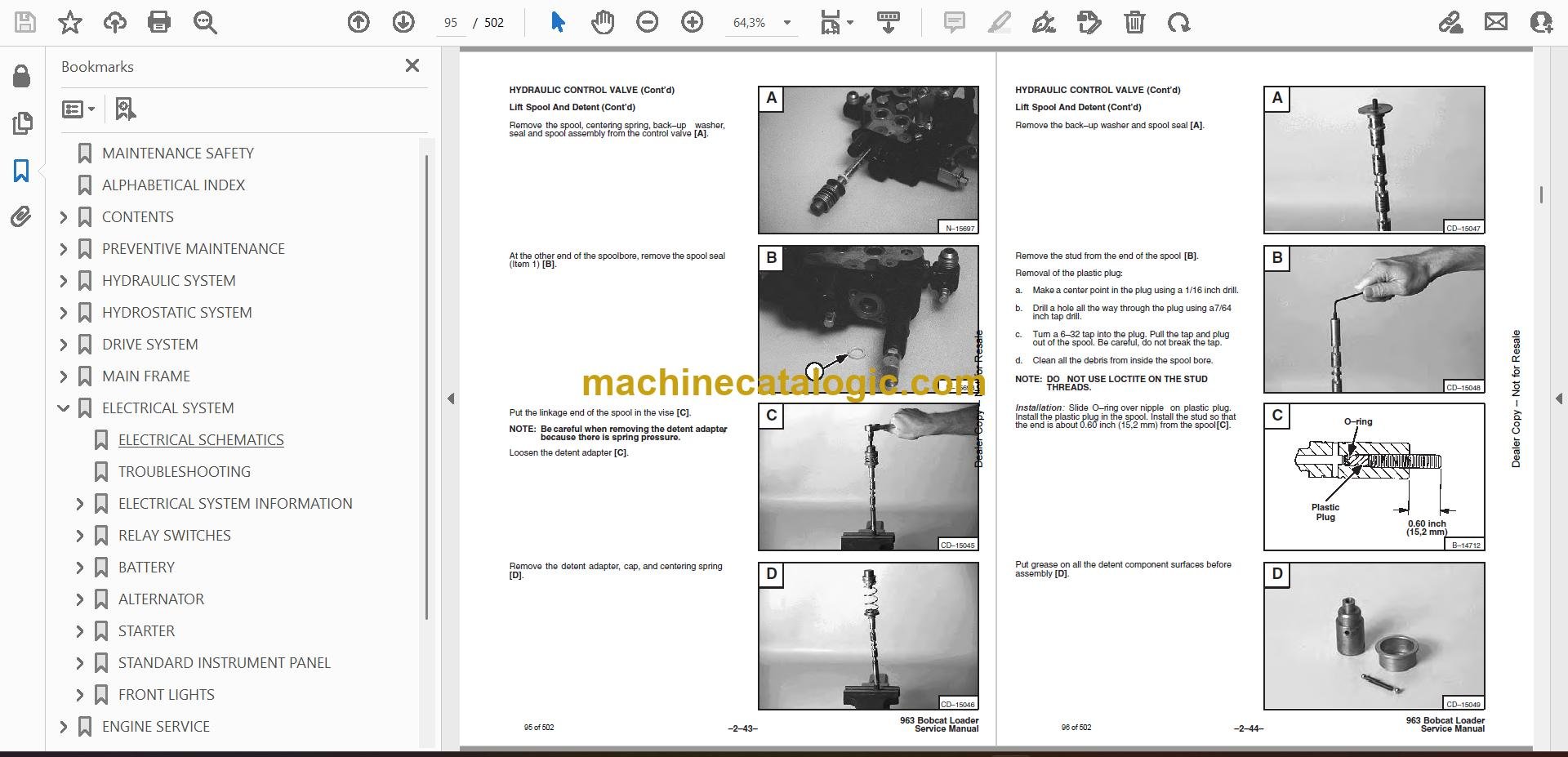
Q: Is this a searchable PDF, and can I read the wiring diagrams clearly?

A: It's a PDF service manual, and these are usually searchable with zoomable wiring diagrams that print fine on regular paper.

Q: How do I know if it fits my exact 963?

A: Check your serial plate. If your 963 falls between 562211001 and 562214999, this is the right manual. If not, you need the manual for your exact range.

Q: Is this what I need for real repairs, or is it just maintenance info?

A: This is the workshop-style service manual, meant for diagnostics and repairs, not just basic maintenance schedules.

Bottom line: If your 963's serial number lands in that range, this is the yes answer for real repair work. If your serial is outside it, this is the wrong book.

📘 Show Index

Table of Contents:

  • MAINTENANCE SAFETY
  • ALPHABETICAL INDEX
  • CONTENTS
    • FOREWORD
    • SAFETY INSTRUCTIONS
    • FIRE PREVENTION
    • SERIAL NUMBER LOCATIONS
    • LOADER SERIAL NUMBER
    • ENGINE SERIAL NUMBER
    • DELIVERY REPORT
    • 963 BOBCAT LOADER IDENTIFICATION
  • PREVENTIVE MAINTENANCE
    • SERVICE SCHEDULE
    • LIFTING AND BLOCKING THE LOADER
      • Procedure
    • TRANSPORTING THE LOADER
      • Procedure
    • TOWING THE LOADER
      • Procedure
    • LIFT ARM SUPPORT DEVICE
      • Engaging The Lift Arm Support Device
      • Disengaging The Lift Arm Support Device
    • OPERATOR CAB
      • Description
      • Raising The Operator Cab
      • Lowering The Operator Cab
      • Emergency Exit
    • SEAT BAR RESTRAINT SYSTEM
      • Description
      • Inspecting The Seat Bar
      • Maintaining The Seat Bar
    • AIR CLEANER SERVICE
      • Replacing Filter Elements
    • FUEL SYSTEM
      • Fuel Specifications
      • Filling The Fuel Tank
      • Fuel Filters
      • Removing Air From The Fuel System
    • ENGINE LUBRICATION SYSTEM
      • Checking Engine Oil
      • Replacing The Oil And Filter
    • ENGINE COOLING SYSTEM
      • Checking The Coolant Level
      • Cleaning The Cooling System
      • Replacing The Coolant
    • ALTERNATOR BELT
      • Adjusting The Alternator Belt
    • HYDRAULIC/HYDROSTATIC SYSTEM
      • Checking And Adding Fluid
      • Hydraulic/Hydrostatic Filter Replacement
      • Replacing The Hydraulic Fluid
    • SPARK ARRESTOR MUFFLER
      • Cleaning Procedure
    • TIRE MAINTENANCE
      • Wheel Nuts
      • Tire Rotation
      • Tire Mounting
    • FINAL DRIVE TRANSMISSION (CHAINCASE)
      • Checking And Adding Oil
    • FAN GEARBOX
      • Checking And Maintaining
    • LUBRICATING THE LOADER
      • Procedure
    • BOB–TACH
      • Inspection And Maintenance
    • REMOTE START SWITCH
      • Procedure
  • HYDRAULIC SYSTEM
    • HYDRAULIC / HYDROSTATIC SCHEMATICS
    • TROUBLESHOOTING
    • HYDRAULIC SYSTEM INFORMATION
      • Tighten Procedures
    • LIFT CYLINDER
      • Checking the Lift Cylinder(s)
      • Removal and Installation
    • TILT CYLINDER
      • Checking The Tilt Cylinder(s)
      • Removal And Installation
    • HYDRAULIC CYLINDER
      • Lift Cylinder Parts Identification
      • Tilt Cylinder Parts Identification
      • Disassembly
      • Assembly
    • TILT JUNCTION BLOCK
      • Removal And Installation
    • MAIN RELIEF VALVE
      • Checking Main Relief Valve At Front Auxiliary Hydraulics
      • Checking Main Relief Valve At Control Valve
      • Removal And Installation
      • Adjustment
    • BICS™ VALVE
      • Lift Arm By–Pass Orifice
      • Lock Valve
      • Check Valve
      • BICS™ Valve Solenoid
      • BICS Valve Removal And Installation
    • HYDRAULIC CONTROL VALVE
      • Removal And Installation
      • Identification Chart
      • Disassembly And Assembly
      • Load Check Valve
      • Main Relief Valve
      • Port Relief Valve (Lift Section)
      • Anti–Cavitation/Port Relief Valve
      • Anti–Cavitation Valve
      • Port Relief Valve (Tilt Section)
      • Rubber Boot
      • Lift Spool And Detent
      • Tilt Spool And Centering Spring
      • Auxiliary Spool
      • Auxiliary Electric Solenoid
      • H–Port – Auxiliary Section
      • Inspection
      • Spool Seal Installation
    • LIFT ARM BY–PASS CONTROL VALVE
      • Removal And Installation
      • Disassembly And Assembly
    • BUCKET POSITION VALVE
      • Removal And Installation
      • Disassembly And Assembly
    • HYDRAULIC PUMP
      • Checking the Output of the Pump
      • Removal And Installation
      • Disassembly And Assembly
      • Inspection
    • HYDRAULIC/HYDROSTATIC FILTER
      • Removal And Installation
    • HYDRAULIC FLUID RESERVOIR
      • Draining The Hydraulic Fluid Reservoir
      • Removal And Installation
    • CONTROL PEDALS
      • Removal And Installation
      • Pedal Adjustment
    • PEDAL INTERLOCK LINKAGE
      • Removal And Installation
      • Adjustment
    • FRONT SIDE PANEL
      • Removal and Installation
    • CONTROL PEDALS MOUNTING PANEL
      • Removal and Installation
  • HYDROSTATIC SYSTEM
    • TROUBLESHOOTING
    • HYDROSTATIC SYSTEM INFORMATION
      • Replenishing Valve Function
      • Checking The Charge Pressure
    • CONTROL PANEL
      • Removal And Installation
    • STEERING LEVERS
      • Disassembly And Assembly
    • STEERING LINKAGE
      • Neutral Adjustment
    • HYDROSTATIC CONTROLLER
      • Removal and Installation
      • Disassembly and Assembly
      • Adjustment
    • HYDROSTATIC MOTOR
      • Removal and Installation
      • Throttle Control
      • Shuttle Check Valve
      • Flushing Valve
      • Disassembly
      • Inspection
      • Assembly
    • HYDROSTATIC PUMP
      • Removal And Installation
      • Hydraulic Pump Removal And Installation
      • Replenishing/High Pressure Relief Valve
      • Charge Relief Valve
      • DA Controller
      • Disassembly
      • Inspection
      • Assembly
      • Hydrostatic Pump Start–Up
      • Timing Procedure
    • DRIVE BELT BELT SHIELD
      • Removal And Installation
    • DRIVE BELT
      • Replacing The Drive Belt
      • Adjusting The Drive Belt
    • DRIVE BELT TENSIONER PULLEY
      • Removal And Installation
      • Tension Spring
      • Disassembly And Assembly
      • Pivot Shaft
    • DRIVE BELT IDLER PULLEY
      • Removal And Installation
    • HYDROSTATIC MOTOR COVER
      • Removal And Installation
    • OIL COOLER
      • Removal And Installation
  • DRIVE SYSTEM
    • PARKING BRAKE PEDAL
      • Removal And Installation
      • Disassembly And Assembly
    • BRAKE/TWO SPEED BLOCK
      • Removal And Installation
      • Disassembly And Assembly
    • PARKING BRAKE
      • Removal And Installation
      • Disassembly And Assembly
    • AXLE SEAL
      • Removal And Installation
    • AXLE, BEARINGS AND SPROCKET
      • Removal And Installation
    • DRIVE CHAINS
      • Removal And Installation
    • FRONT CHAINCASE COVER
      • Removal And Installation
    • REAR CHAINCASE COVER
      • Removal and Installation
    • REDUCTION GEARCASE
      • Removal And Installation
      • Disassembly And Assembly
    • CHAINCASE FLUID
      • Removing The Fluid From The Chaincase
  • MAIN FRAME
    • SEAT BAR
      • Removal And Installation
      • Assembling Components
      • Compression Spring Disassembly And Assembly
    • OPERATOR CAB GAS CYLINDER
      • Removal And Installation
      • Gas Cylinder Mounting Bracket
    • OPERATOR CAB
      • Removal And Installation
    • OPERATOR SEAT
      • Removal And Installation
    • BOB–TACH
      • Removal And Installation
      • Bob–Tach Lever And Wedge
      • Bob–Tach Stops
    • LIFT ARMS
      • Removal And Installation
    • REAR GRILL
      • Gas Cylinder Removal And Installation
      • Removal And Installation
    • REAR DOOR
      • Removal And Installation
      • Adjusting The Rear Door Latch
    • FRONT FUEL TANK
      • Removal And Installation
      • Fuel Level Sender
    • REAR FUEL TANK
      • Removal And Installation
      • Pickup Tube Screen
  • ELECTRICAL SYSTEM
    • ELECTRICAL SCHEMATICS
    • TROUBLESHOOTING
    • ELECTRICAL SYSTEM INFORMATION
      • Description
      • Fuse Location
    • RELAY SWITCHES
      • Location
    • BATTERY
      • Removal And Installation
      • Servicing The Electrical System
      • Using A Booster Battery (Jump Starting)
    • ALTERNATOR
      • Alternator Output Test
      • Rectifier (Diode) Test
      • Alternator Regulator Test
      • Removal And Installation
      • Adjusting the Alternator Belt
      • Disassembly
      • Stator Continuity Test
      • Stator Ground Test
      • Rotor Continuity Test
      • Rotor Ground Test
      • Rectifier Continuity (Diode) Test
      • Assembly
    • STARTER
      • Removal And Installation
      • Parts Identification
      • Disassembly And Assembly
      • External Pinion
      • Inspection And Repair
      • Magnetic Switch Test
      • No Load Test
    • STANDARD INSTRUMENT PANEL
      • Removal And Installation
    • FRONT LIGHTS
      • Removal And Installation
  • ENGINE SERVICE
    • TROUBLESHOOTING
    • ENGINE SPEED CONTROL
      • Removal And Installation
    • ENGINE MUFFLER
      • Removal And Installation
      • Exhaust Extension Pipe
    • AIR CLEANER HOUSING
      • Removal And Installation
    • COOLANT RECOVERY TANK
      • Removal And Installation
    • RADIATOR
      • Removal And Installation
    • FAN DRIVE TENSION PULLEY
      • Removal And Installation
    • FAN GEARBOX/BLOWER HOUSING
      • Removal And Installation
    • BLOWER FAN
      • Removal And Installation
    • FAN GEARBOX
      • Disassembly
      • Assembly
      • Checking Backlash
    • FLYWHEEL
      • Removal And Installation
      • Ring Gear Removal
      • Ring Gear Installation
    • ENGINE MOUNTING BRACKET
      • Removal and Installation
    • VALVE CLEARANCE
      • Adjustment
    • FUEL LIFT PUMP
      • Checking
      • Removal And Installation
    • FUEL INJECTION PUMP
      • Removal And Installation
    • FUEL INJECTOR NOZZLES
      • Removal and Installation
      • Checking
    • ENGINE
      • Removal And Installation
    • INTAKE MANIFOLD
      • Removal and Installation
    • EXHAUST MANIFOLD
      • Removal and Installation
    • CYLINDER HEAD
      • Removal
      • Inspection
      • Installation
    • ROCKER SHAFT
      • Disassembly And Assembly
    • VALVES, VALVE GUIDES AND SPRINGS
      • Valve Removal
      • Checking Valve Springs
      • Checking Valve Depth
      • Checking Valve Guides
      • Valve Guide Removal
      • Valve Guide Installation
      • Checking Valves
      • Cutting A Valve Seat
      • Assembly
      • Changing Valve Springs (With Cylinder Head Installed)
    • TIMING CASE AND DRIVE ASSEMBLY
      • Description
      • Timing Cover Removal
      • Timing Cover Installation
      • Front Oil Seal Removal
      • Front Oil Seal Installation
      • Timing Case And Gear Removal
      • Timing Case And Gear Installation
    • CAMSHAFT AND TAPPETS
      • Removal
      • Installation
    • PISTONS AND CONNECTING RODS
      • Description
      • Removal
      • Disassembly
      • Piston Ring End Gap
      • Piston Ring Installation
      • Piston Ring Groove Clearance
      • Connecting Rod Inspection
      • Connecting Rod Bushing Replacement
      • Assembly
      • Installation
      • Checking Piston Height
    • CRANKSHAFT AND BEARINGS
      • Description
      • Removal
      • Inspection Of Crankshaft And Bearings
      • Installation
      • Rear Oil Seal Removal
      • Rear Oil Seal Housing Positioning
      • Rear Oil Seal Installation
      • Checking Crankshaft End Play
    • COOLING SYSTEM
      • Description
      • Thermostat Removal and Installation
      • Thermostat Testing
      • Water Pump Removal
      • Water Pump Installation
    • ENGINE OIL COOLER
      • Removal and Installation
      • Disassembly and Assembly
    • LUBRICATION SYSTEM
      • Description
      • Oil Filter Adapter Removal
      • Oil Filter Adapter Installation
      • Oil Pan Removal And Installation
      • Oil Screen And Pick–up Tube
      • Oil Pump Removal
      • Oil Pump Installation
      • Oil Pump Disassembly And Assembly
      • Oil Pressure Relief Valve Disassembly And Assembly
    • ENGINE BLOCK
      • Description
      • Disassembly And Assembly
      • Piston Cooling Jet Removal
      • Piston Cooling Jet Installation
      • Piston Cooling Jet Alignment
      • Inspection
      • Cylinder Liner Inspection
      • Cylinder Liner Removal
      • Cylinder Liner Installation
    • TURBOCHARGER
      • Troubleshooting
      • Description
      • Removal and Installation
  • SYSTEMS ANALYSIS
    • BICS™ (With Press To Operate Button)
      • Inspecting The BICS™ Controller (Engine STOPPED – Key ON)
      • Inspecting Deactivation Of The Auxiliary Hydraulics System (Engine STOPPED – Key ON)
      • Inspecting The Seat Bar Sensor (Engine RUNNING)
      • Inspecting The Traction Lock (Engine RUNNING)
      • Inspecting The Lift Arm By–Pass Control
      • Additional Inspection For Advanced Hand Controls
      • Troubleshooting Chart
    • BICS™ (Without Press To Operate Button)
      • Inspecting The BICS™ Controller (Engine STOPPED – Key ON)
      • Inspecting Deactivation Of The Auxiliary Hydraulics System (Engine STOPPED – Key ON)
      • Inspecting The Seat And Seat Bar Sensors (Engine RUNNING)
      • Inspecting The Traction Lock (Engine RUNNING)
      • Inspecting The Lift Arm By–Pass Control
      • Maintenance
      • Troubleshooting Chart
    • SEAT SENSOR OVERRIDE ONLY (If Equipped)
    • BICS™ SYSTEM CONTROLLER
      • Troubleshooting Guide
      • Removal And Installation
    • SEAT BAR SENSOR
      • Troubleshooting Guide
      • Seat Bar Sensor Test
      • Removal And Installation
      • BICS™ Controller Seat Bar Sensor Circuit Test
    • SEAT SENSOR
      • Troubleshooting Guide
      • Seat Sensor Test
      • Removal And Installation
      • BICS™ Controller Seat Sensor Circuit Test
    • TRACTION LOCK
      • Troubleshooting Guide
    • BOSS® DIAGNOSTIC TOOL
      • Procedure
    • SENDER AND SENSOR
      • Service Checks
      • Components
      • Adjustment
    • MONITOR SERVICE CODES
    • TROUBLESHOOTING THE BOSS® & LCD DISPLAY
    • BOSS® UNIT
      • Removal and Installation
    • BOSS® INSTRUMENT PANEL
      • Removal and Installation
    • PWM MODULE
      • Description
    • PWM TROUBLESHOOTING
      • Conditions
      • Chart
    • PWM CONTROL HANDLE
      • Handle Testing
    • PWM ELECTRIC SOLENOID
      • Solenoid Coil Testing
    • ELECTRICAL/HYDRAULIC CONTROLS REFERENCE
      • Controls Identification Chart
  • SPECIFICATIONS
    • LOADER SPECIFICATIONS
      • Performance
      • Controls
      • Engine
      • Hydraulic System
      • Electrical
      • Drive System
      • Capacities
      • Tires
    • ENGINE SPECIFICATIONS
      • General
      • Cylinder Head
      • Valve Guides
      • Exhaust Valves
      • Intake Valves
      • Valve Springs
      • Rocker Shaft, Rockers And Bushings
      • Pistons And Piston Rings
      • Connecting Rods And Bearings
      • Crankshaft
      • Crankshaft Re–Grind Data
      • Main Bearings
      • Thrust Washers
      • Camshaft And Thrust Washer
      • Cylinder Block
      • Cylinder Liners
      • Fuel Injection Pump
      • Fuel Injectors
      • Fuel Lift Pump
      • Timing Case And Timing Gears
      • Oil Pump, Gear And Relief Valve
      • Turbocharger
      • Flywheel
      • Water Pump And Thermostat
      • Engine Torque
    • LOADER TORQUE
    • TORQUE SPECIFICATIONS FOR BOLTS
      • Torque For General SAE Bolts
      • Torque For General Metric Bolts
    • HYDRAULIC CONNECTION SPECIFICATIONS
      • O–ring Face Seal Connection
      • Straight Thread O–ring Fitting
      • Tubelines And Hoses
      • Flare Fitting
      • O–ring Flare Fitting
      • Port Seal Fitting
    • HYDRAULIC/HYDROSTATIC FLUID SPECIFICATIONS
    • DECIMAL AND MILLIMETER EQUIVALENTS
    • U.S. TO METRIC CONVERSION
  • ADVANCE HAND CONTROL SYSTEM (A.H.C)
    • A.H.C. COMPONENTS
      • Identification
    • TROUBLESHOOTING (A.H.C.)
    • ACTUATOR VOLTAGE TEST
      • Procedure
    • HANDLE CONTROL UNIT TEST
      • Procedure
    • BOBCAT INTERLOCK CONTROL SYSTEM (BICS™)
      • Troubleshooting Chart
    • SEAT SENSOR OVERRIDE ONLY
    • ADVANCED HAND CONTROLS (AHC)
    • A.H.C./PWM CONTROLLER
      • Removal and Installation
      • Description
      • Conditions
      • Troubleshooting Chart
      • Handle Testing
      • Solenoid Coil Testing
    • HANDLE CONTROL UNIT
      • Removal And Installation
      • Control Unit Connector
    • SWITCH HANDLE
      • Removal and Installation
    • A.H.C. HANDLE
      • Removal and Installation
      • Disassembly and Assembly
    • A.H.C. STEERING LEVER
      • Removal and Installation
      • Steering Lever Boot
      • Disassembly and Assembly
    • BICS™ VALVE
      • Lift Arm By–Pass Orifice
      • Check Valve
      • Lock Valve
      • BICS™ Valve Solenoid
      • Removal and Installation
    • HYDRAULIC CONTROL VALVE
      • Removal And Installation
      • Mounting Plate
      • Identification Chart
      • Disassembly and Assembly
      • Load Check Valve
      • Main Relief Valve
      • Port Relief Valve (Lift)
      • Anti–Cavitation/Port Relief Valve
      • Port Relief Valve (Tilt)
      • Anti–Cavitation Valve
      • Rubber Boot
      • Lift and Tilt Spool
      • Inspection
      • Auxiliary Spool
      • Auxiliary Electrical Solenoid
      • H–Port Auxiliary Section
      • Spool Seal Installation
  • SERVICE MANUAL REVISIONS
    • 963–1
    • 963–2
    • 963–3
    • 963–4
    • 963-5

Bobcat Software

Bobcat PDF Manuals

Related Manuals

0
    0
    Your Cart
    Your cart is emptyReturn to Shop