A T3571 VersaHANDLER on a job is loading trucks, staging pallets, and reaching over obstacles where a skid steer just can't. The people who grab this service manual are the ones actually fixing it when it quits lifting, creeps, or throws an electrical fault, whether that's in a farm yard or a tight rental lot. They want wiring diagrams that make sense, hydraulic test points, and step-by-step teardown so they're not wasting a day and three parts runs guessing.
What this manual helps you do
- Diagnose boom, outrigger, and steering hydraulic issues, then check pressures and isolate bad valves or cylinders
- Trace electrical faults in boom functions, lights, safety switches, and sensors using readable wiring diagrams
- Follow step sequences to remove and replace drive components, axles, and major structural parts without wrecking anything expensive
- Rebuild or reseal hydraulic cylinders and key valve sections with correct disassembly and reassembly order
- Adjust telescopic boom, attachment coupler, and safety interlocks so lift, reach, and shutdown systems work like they should
Who this is for
This is for anyone working on a Bobcat T3571 VersaHANDLER TTC telescopic handler in the A8H611001 to A8H699999 serial range: small contractors, farm and rental fleet mechanics, owner-operators, and field techs like me. If you just need basic operating tips or daily checks, you want the operator's handbook instead.
FAQ
Q: Is this a searchable PDF, and can I read the wiring diagrams on a laptop or tablet?
A: These manuals are usually searchable PDFs, and the diagrams are laid out so you can zoom in and read pin numbers and wire colors.
Q: How do I know if it matches my exact machine?
A: Check your serial plate. If your T3571 falls between A8H611001 and A8H699999, this is the correct service manual family.
Q: Is this the right document if I'm doing my own repairs?
A: Yes, if you're doing real repair work or diagnostics. For parts ordering, you still need a separate parts catalog.
Bottom line: If your T3571 serial number is in that A8H611001-A8H699999 window and you're turning wrenches on it, this is the right manual. If not, keep looking for your exact serial range.
📘 Show Index
Table of Contents:
- MAINTENANCE SAFETY
- CONTENTS
- FOREWORD
- FOREWORD
- SAFETY INSTRUCTIONS
- FIRE PREVENTION
- Maintenance
- Operation
- Electrical
- Hydraulic System
- Fueling
- Starting
- Spark Arrester Exhaust System
- Welding And Grinding
- Fire Extinguishers
- SERIAL NUMBER LOCATION
- Telescopic Handler Serial Number
- Engine Serial Number
- Other Serial Numbers
- DELIVERY REPORT
- IDENTIFICATION OF THE TELESCOPIC HANDLER
- SAFETY & MAINTENANCE
- LIFTING AND BLOCKING THE TELESCOPIC HANDLER
- OPERATOR CAB (ROPS / FOPS)
- TRANSPORTING THE TELESCOPIC HANDLER ON A TRAILER
- Loading And Unloading
- Fastening
- TOWING THE TELESCOPIC HANDLER
- SERVICE SCHEDULE
- AIR CLEANER SERVICE
- ENGINE COOLING SYSTEM
- Cleaning
- Removing And Replacing The Coolant
- Checking Level
- FUEL SYSTEM
- Fuel Specifications
- Biodiesel Blend Fuel
- Filling The Fuel Tank
- Secondary Fuel Filter
- Primary Fuel Filter (Pre-Filter)
- Removing Air From The Fuel System
- ENGINE LUBRICATION SYSTEM
- Checking And Adding Engine Oil
- Engine Oil Chart
- Removing And Replacing Oil And Filter
- HYDRAULIC / HYDROSTATIC SYSTEM
- Checking And Adding Fluid
- Hydraulic / Hydrostatic Fluid Chart
- Removing And Replacing Hydraulic Fluid
- Removing And Replacing Hydraulic / Hydrostatic Filter
- Hydraulic Tank Breather
- ATTACHMENT CARRIER
- Inspection And Maintenance
- AXLES (FRONT AND REAR)
- Checking And Adding Oil (Planetary Carrier)
- Removing And Replacing Oil (Planetary Carrier)
- Checking And Adding Oil (Rear Differential)
- Removing And Replacing Oil (Rear Differential)
- Checking And Adding Oil (Front Differential)
- Removing And Replacing Oil (Front Differential)
- Checking And Adding Oil (Front Drop Box)
- Removing And Replacing Oil (Front Drop Box)
- LUBRICATING THE TELESCOPIC HANDLER
- TIRE MAINTENANCE
- Wheel Nuts
- Rotation
- Mounting
- APPROVED BOOM STOP
- Installing The Approved Boom Stop
- Removing The Approved Boom Stop
- ENGINE COVER
- TELESCOPIC HANDLER STORAGE AND RETURN TO SERVICE
- Storage
- Return To Service
- STOPPING THE ENGINE AND LEAVING THE TELESCOPIC HANDLER
- EMERGENCY EXIT
- HYDRAULIC SYSTEM
- HYDRAULIC SCHEMATIC
- HYDRAULIC SYSTEM INFORMATION
- Glossary Of Hydraulic / Hydrostatic Symbols
- Troubleshooting Chart
- Tightening Procedures
- LIFT CYLINDER
- Removal And Installation
- Parts Identification
- Disassembly
- Assembly
- BUCKET POSITIONING CYLINDER
- Removal And Installation
- Parts Identification
- Disassembly
- Assembly
- EXTENSION CYLINDER
- Cylinder Group Removal And Installation
- Upper Tubeline Removal
- Upper Tubeline Installation
- Extension Cylinder Removal And Installation
- Tubeline Tray Disassembly
- Tubeline Tray Assembly
- Parts Identification
- Disassembly
- Assembly
- TILT CYLINDER
- Removal And Installation
- Parts Identification
- Disassembly
- Assembly
- STEERING CYLINDER (FRONT)
- Removal
- Installation
- Disassembly
- Assembly
- STEERING CYLINDER (REAR)
- Removal
- Installation
- Disassembly
- Assembly
- DRIVE BOX
- Parts Identification
- Disassembly
- Assembly
- Special Tools
- MAIN RELIEF VALVE
- Testing And Adjustment
- Removal And Installation
- QUICK-TACH CYLINDER
- Removal And Installation
- Parts Identification
- Disassembly
- Assembly
- FRAME LEVELING CYLINDER
- Removal And Installation
- Parts Identification
- Disassembly
- Assembly
- STEERING MODE VALVE BLOCK
- Removal And Installation
- Parts Identification
- Disassembly
- Solenoid Testing
- Assembly
- BRAKE VALVE
- Removal And Installation
- Disassembly And Assembly
- GEAR PUMP
- Removal And Installation
- Parts Identification
- Disassembly And Assembly
- FAN MOTOR
- Removal And Installation
- Parts Identification
- Disassembly And Assembly
- HYDRAULIC FLUID RESERVOIR
- STEERING VALVE
- Removal And Installation
- Parts Identification
- Disassembly
- Inspection
- Assembly
- HYDRAULIC CONTROL VALVE
- Troubleshooting Chart (Controllers)
- Telescoping Valve Section Troubleshooting
- Auxiliary Valve Section Troubleshooting
- Troubleshooting Chart (Control Valve)
- Removal And Installation
- Parts Identification
- Disassembly And Assembly
- End Housing Disassembly And Assembly
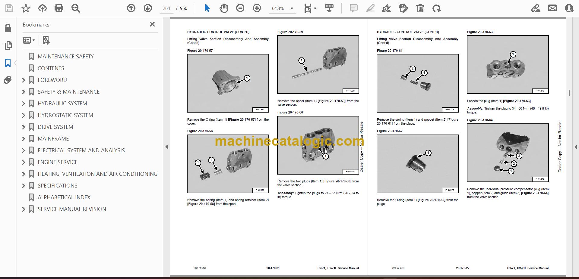
- Lifting Valve Section Disassembly And Assembly
- Tilting Valve Section Disassembly And Assembly
- Telescoping Valve Section Disassembly And Assembly
- Auxiliary / Frame Leveling Valve Section Disassembly And Assembly
- Inlet-Outlet Valve Section Disassembly And Assembly
- PORT RELIEF VALVES
- FLOW CONTROL VALVE
- JOYSTICK
- PARKING BRAKE
- Pressure Switch Removal And Installation
- Pressure Switch Disassembly And Assembly
- Parking Brake Valve Removal And Installation
- Parking Brake Valve Disassembly And Assembly
- PRESSURE REDUCING VALVE
- Testing
- Removal And Installation
- Disassembly And Assembly
- ACCUMULATOR
- TOW VALVE
- Removal And Installation
- Disassembly And Assembly
- HYDROSTATIC SYSTEM
- HYDROSTATIC SYSTEM INFORMATION
- Troubleshooting Chart
- Replenishing Valve Function
- OIL COOLER
- HYDROSTATIC DRIVE MOTOR
- Removal And Installation
- Parts Identification
- Disassembly
- Inspection
- Assembly
- HYDROSTATIC PUMP
- Removal And Installation
- Parts Identification
- Disassembly
- Inspection
- Assembly
- DRIVE SYSTEM
- TROUBLESHOOTING
- AXLE AND DIFFERENTIAL (FRONT)
- General Information
- Planetary Carrier Parts Identification
- Planetary Carrier Disassembly
- Steering Knuckle And Drive Axle Parts Identification
- Steering Knuckle Disassembly
- Drive Axle Disassembly
- Brake System Parts Identification
- Brake System Disassembly
- Differential Parts Identification
- Differential Disassembly
- Bevel Pinion Parts Identification
- Bevel Pinion Disassembly
- Bevel Pinion Assembly
- Differential Assembly
- Brake System Assembly
- Drive Axle Assembly
- Steering Knuckle Assembly
- Planetary Carrier Assembly
- Special Tools
- AXLE AND DIFFERENTIAL (REAR)
- General Information
- Planetary Carrier Parts Identification
- Steering Knuckle And Drive Axle Parts Identification
- Steering Knuckle Disassembly
- Differential And Bevel Pinion Parts Identification
- Differential Disassembly
- Bevel Pinion Disassembly
- Bevel Pinion Assembly
- Differential Assembly
- Steering Knuckle Assembly
- Planetary Carrier Assembly
- Special Tools
- FRONT AXLE
- AXLE TOE-IN
- PARKING BRAKE
- Releasing The Brake For Towing
- Re-Activating The Brake
- STEERING ANGLE ADJUSTMENT
- DRIVE SHAFT
- SERVICE BRAKE
- Description
- Bleeding The Brake Circuit
- REAR AXLE
- MAINFRAME
- OPERATOR CAB (S/N A8HF12999 & BELOW, S/N A8H612999 & BELOW)
- OPERATOR CAB (S/N A8HF13000 & ABOVE, S/N A8H613000 & ABOVE)
- OPERATOR SEAT
- BOOM ASSEMBLY
- INNER BOOM
- WEAR PADS (FRONT)
- WEAR PADS (REAR)
- ENGINE COVER
- Gas Cylinder Removal And Installation
- Removal And Installation
- AIR INTAKE COWLING
- FUEL TANK
- QUICK-TACH
- REAR WEIGHTS
- FENDER
- PIVOT LINK
- JOYSTICK PANEL (S/N A8HF12999 & BELOW, S/N A8H612999 & BELOW)
- JOYSTICK PANEL (S/N A8HF13000 & ABOVE, S/N A8H613000 & ABOVE)
- DASH COVER / STEERING COLUMN COVER (S/N A8HF12999 & BELOW, S/N A8H612999 & BELOW)
- DASH COVER / STEERING COLUMN COVER (S/N A8HF13000 & ABOVE, S/N A8H613000 & ABOVE)
- ELECTRICAL SYSTEM AND ANALYSIS
- ELECTRICAL SCHEMATIC
- ELECTRICAL SYSTEM INFORMATION (S/N A8HF12999 & BELOW, S/N A8H612999 & BELOW)
- Troubleshooting Chart
- Description
- Fuses, Diodes And Relay Location / Identification
- ELECTRICAL SYSTEM INFORMATION (S/N A8HF13000 & ABOVE, S/N A8H613000 & ABOVE)
- Troubleshooting Chart
- Description
- Fuses, Diode And Relay Location / Identification
- BATTERY
- Removal And Installation
- Servicing
- Using A Booster Battery (Jump Starting)
- ALTERNATOR
- Removal And Installation
- Belt Adjusting
- Belt Replacement
- STARTER
- Testing
- Removal And Installation
- LIGHTS
- Rear Light Removal And Installation
- Front Light Removal And Installation
- TRAVEL / SIGNAL LEVER (S/N A8HF12999 & BELOW, S/N A8H612999 & BELOW)
- TRAVEL / SIGNAL LEVER (S/N A8HF13000 & ABOVE, S/N A8H613000 & ABOVE)
- INSTRUMENT PANEL
- SWITCH PANEL (S/N A8HF12999 & BELOW, S/N A8H612999 & BELOW)
- Removal And Installation
- Parts description
- SWITCH PANEL (S/N A8HF13000 – 14999, S/N A8H613000 – 14999)
- SWITCH PANEL (S/N A8HF15000 & ABOVE, S/N A8H615000 & ABOVE)
- BRAKE LIGHT SWITCH
- Removal And Installation
- Adjustment
- WIPER MOTOR (FRONT)
- WIPER MOTOR (TOP)
- WIPER MOTOR (REAR)
- PEDAL ASSEMBLY
- Removal And Installation
- Disassembly And Assembly
- INCHING SWITCH
- Removal And Installation
- Adjustment
- SERVICE SOFTWARE
- Connecting The Laptop Computer
- Entering The Service Software
- Monitor Screen
- Warnings Screen
- Calibrate Inch Pedal
- Calibrate Creep Potentiometer
- Program / Update Susmic Controller
- FRAME LEVEL SPEED SWITCH
- Description
- Removal
- Installation
- LONGITUDINAL STABILITY INDICATOR CALIBRATION (S/N A8HF11001-14999, S/N A8H611001-14999)
- Fitting The Sensor
- Calibration Procedure
- LLMI / LLMC SYSTEM (S/N A8HF15000 & ABOVE, S/N A8H615000 & ABOVE)
- System Calibration
- Calibration Test
- System Failure Reports
- System Components Identification
- LLMS Removal
- LLMS Installation
- LLMC Controller Removal
- LLMC Controller Installation
- ENGINE SERVICE
- ENGINE INFORMATION
- Specifications
- Troubleshooting
- ENGINE SPEED CONTROL
- MUFFLER
- AIR CLEANER
- Housing Removal And Installation
- OIL COOLER / RADIATOR
- Removal And Installation
- Disassembly And Assembly
- ENGINE AND ENGINE MOUNTS
- ENGINE COMPONENTS AND TESTING
- Fuel Injection Pump Removal
- Fuel Injection Pump Installation
- Fuel Injector Removal And Installation
- Checking The Fuel Lift Pump
- Fuel Lift Pump Removal And Installation
- Compression Checking
- Glow Plug Checking
- Glow Plugs Removal And Installation
- ENGINE TIMING
- ENGINE / HYDROSTAT ASSEMBLY
- FLYWHEEL AND HOUSING
- Removal And Installation
- Ring Gear Removal
- Ring Gear Installation
- RECONDITIONING THE ENGINE
- Turbocharger Troubleshooting
- Turbocharger Description
- Turbocharger Removal And Installation
- Exhaust Manifold Removal And Installation
- Fuel Injector Cover Removal And Installation
- Rocker Cover Removal And Installation
- Cylinder Head Removal
- Cylinder Head Inspection
- Cylinder Head Installation
- Rocker Shaft Disassembly And Assembly
- Valve Removal
- Valve Springs Checking
- Valve Depth Checking
- Valve Guides Checking
- Valve Guide Removal
- Valve Guide Installation
- Valves Checking
- Cutting Valve Seat
- Valve Seat Assembly
- Changing Valve Springs (With Cylinder Head Installed)
- Valve Clearance Adjustment
- Timing Case And Drive Assembly Description
- Timing Cover Removal
- Timing Cover Installation
- Crankshaft Pulley Removal And Installation
- Front Oil Seal Removal And Installation
- Timing Case And Gear Removal
- Timing Case And Gear Installation
- Camshaft And Tappets Removal
- Camshaft And Tappets Installation
- Pistons And Connecting Rods Description
- Pistons And Connecting Rods Removal
- Pistons And Connecting Rods Disassembly
- Piston Ring End Gap
- Piston Ring Installation
- Piston Ring Groove Clearance
- Connecting Rod Inspection
- Connecting Rod Bushing Replacement
- Piston And Connecting Rod Assembly
- Piston And Connecting Rod Installation
- Checking Piston Height
- Crankshaft And Bearings Description
- Crankshaft And Bearings Removal
- Inspection Of Crankshaft And Bearings
- Crankshaft And Bearings Installation
- Rear Oil Seal Removal
- Rear Oil Seal Housing Positioning
- Rear Oil Seal Installation
- Checking Crankshaft End Play
- Cooling System Description
- Thermostat Removal and Installation
- Thermostat Testing
- Lubricating Oil Cooler Removal And Installation
- Water Pump Removal
- Water Pump Installation
- Engine Lubrication System Description
- Oil Filter Adapter Removal And Installation
- Oil Pan Removal And Installation
- Oil Screen And Pick-Up Tube
- Oil Pump Removal
- Oil Pump Removal (Cont'd)
- Oil Pump Installation
- Oil Pump Installation (Cont'd)
- Oil Pump Disassembly And Assembly
- Oil Pump Disassembly And Assembly (Cont'd)
- Oil Pressure Relief Valve Disassembly And Assembly
- Engine Block Description
- Engine Block Disassembly And Assembly
- Piston Cooling Jet Removal
- Piston Cooling Jet Installation
- Piston Cooling Jet Alignment
- Inspection
- Cylinder Liner Inspection
- Cylinder Liner Removal
- Cylinder Liner Installation
- HEATING, VENTILATION AND AIR CONDITIONING
- AIR CONDITIONING SYSTEM FLOW
- Description
- Chart
- Components
- Safety Equipment
- REGULAR MAINTENANCE
- Filters
- Compressor And Alternator Drive Belt Inspection
- Cleaning The Condenser
- Air Conditioning Lubrication
- Air Conditioning Service Chart
- TROUBLESHOOTING
- Blower Motor Does Not Operate
- Blower Motor Operates Normally, But Air Flow Is Insufficient
- Insufficient Cooling Although Air Flow And Compressor Operation Are Normal
- The Compressor Does Not Operate At All, Or Operates Improperly
- Gauge Pressure Related Troubleshooting
- Gauge Pressure Related Troubleshooting (Cont’d)
- Troubleshooting Tree
- Temperature / Pressure Chart
- Poor A/C Performance
- HVAC Repair And Leaks
- Electrical System
- SYSTEM CHARGING AND RECLAMATION
- Reclamation Procedure
- Charging Procedure With A Manifold Gauge Set
- Charging Procedure
- COMPRESSOR
- Removal And Installation
- Oil Check
- Compressor Clutch Disassembly And Assembly
- Oil
- CONDENSER (S/N A8HF12999 & BELOW, S/N A8H612999 & BELOW)
- CONDENSER (S/N A8HF13000 & ABOVE, S/N A8H613000 & ABOVE)
- RECEIVER / DRIER
- PRESSURE SWITCH
- EVAPORATOR / BLOWER UNIT (S/N A8HF12999 & BELOW, S/N A8H612999 & BELOW)
- EVAPORATOR / BLOWER UNIT (S/N A8HF13000 & ABOVE, S/N A8H613000 & ABOVE)
- EXPANSION VALVE (S/N A8HF12999 & BELOW, S/N A8H612999 & BELOW)
- EXPANSION VALVE (S/N A8HF13000 & ABOVE, S/N A8H613000 & ABOVE)
- HEATER ASSEMBLY
- Removal And Installation
- Fan Removal And Installation
- Core Removal And Installation
- SPECIFICATIONS
- (T3571) TELESCOPIC HANDLER SPECIFICATIONS
- Machine Dimensions
- Performance
- Weights
- Engine
- Controls
- Drive System
- Traction
- Steering
- Brakes
- Fluid Capacities
- Hydraulic System
- Electrical System
- Instrument Panel
- Environmental
- Temperature Range
- (T3571L) TELESCOPIC HANDLER SPECIFICATIONS
- Dimensional Specifications
- Performance Specifications
- Weights
- Engine
- Controls
- Drive System
- Traction
- Steering
- Brakes
- Fluid Capacities
- Hydraulic System
- Electrical
- Instruments
- Environmental
- Temperature Range
- MACHINE TORQUE SPECIFICATIONS
- Axle
- Boom
- Drive Box
- Drive Motor
- Engine
- Hydraulic Pump
- TORQUE SPECIFICATIONS FOR BOLTS
- Torque for General SAE Bolts
- Torque For General Metric Bolts
- HYDRAULIC CONNECTION SPECIFICATIONS
- O-ring Face Seal Connection
- Straight Thread O-ring Fitting
- Tubelines And Hoses
- Port Seal Fitting
- HYDRAULIC / HYDROSTATIC FLUID SPECIFICATIONS
- CONVERSIONS
- Decimal And Millimeter Equivalents
- U.S. To Metric Conversion
- ALPHABETICAL INDEX
- SERVICE MANUAL REVISION
- Revision No: T3571, T3571L – 1
- Revision No: T3571, T3571L – 2
- Revision No: T3571, T3571L – 3
Bobcat Software
Bobcat PDF Manuals


