$ 0
0
$ 0
0

Bobcat B750 Backhoe Loader Service Manual (SN B45211001-B45299999)

Format: PDF (Printable Document)

File Language: English

File Pages: 1185

File Size: 42.39 MB (Speed Download Link)

Brand: Bobcat

Model: B750 Backhoe Loader

Book No: 7286757

Serial No: SN B45211001-B45299999

Type of Document: Service Manual

Categories: ,

$ 45

Share:

Bobcat B750 Backhoe Loader Service Manual (SN B45211001-B45299999)

The Bobcat B750 backhoe loader is a yard and jobsite workhorse, doing trenching, loading trucks, and material handling all week long. The people who grab this service manual are the ones actually turning wrenches: shop mechanics, field techs, and owners trying to keep downtime off the schedule. They want torque specs, hydraulic test points, and step-by-step teardown so a repair gets done once and done right. If you're chasing leaks, low power, or electrical gremlins on a B750 in the listed serial range, this is the book you reach for.

What this manual helps you do

  • Diagnose hydraulic problems on loader and backhoe functions, then pressure-test and adjust components correctly
  • Trace and troubleshoot electrical faults using wiring diagrams, connector views, and test procedures
  • Follow step-by-step procedures to remove, rebuild, and reinstall major components like pumps, cylinders, and drive parts
  • Check and set adjustments on linkages, brakes, steering, and attachment systems so the machine runs within spec
  • Verify maintenance intervals and service points for engine, cooling, fuel, and lubrication to plan 50/250/500-hour work

Who this is for

This manual is for anyone maintaining or repairing a Bobcat B750 backhoe loader in a shop or field setting: small contractors, rental fleets, owner-operators, and independent mechanics. If you only want operating tips, safety info, or basic fluid checks, you need the operator's handbook instead, not this service manual.

FAQ

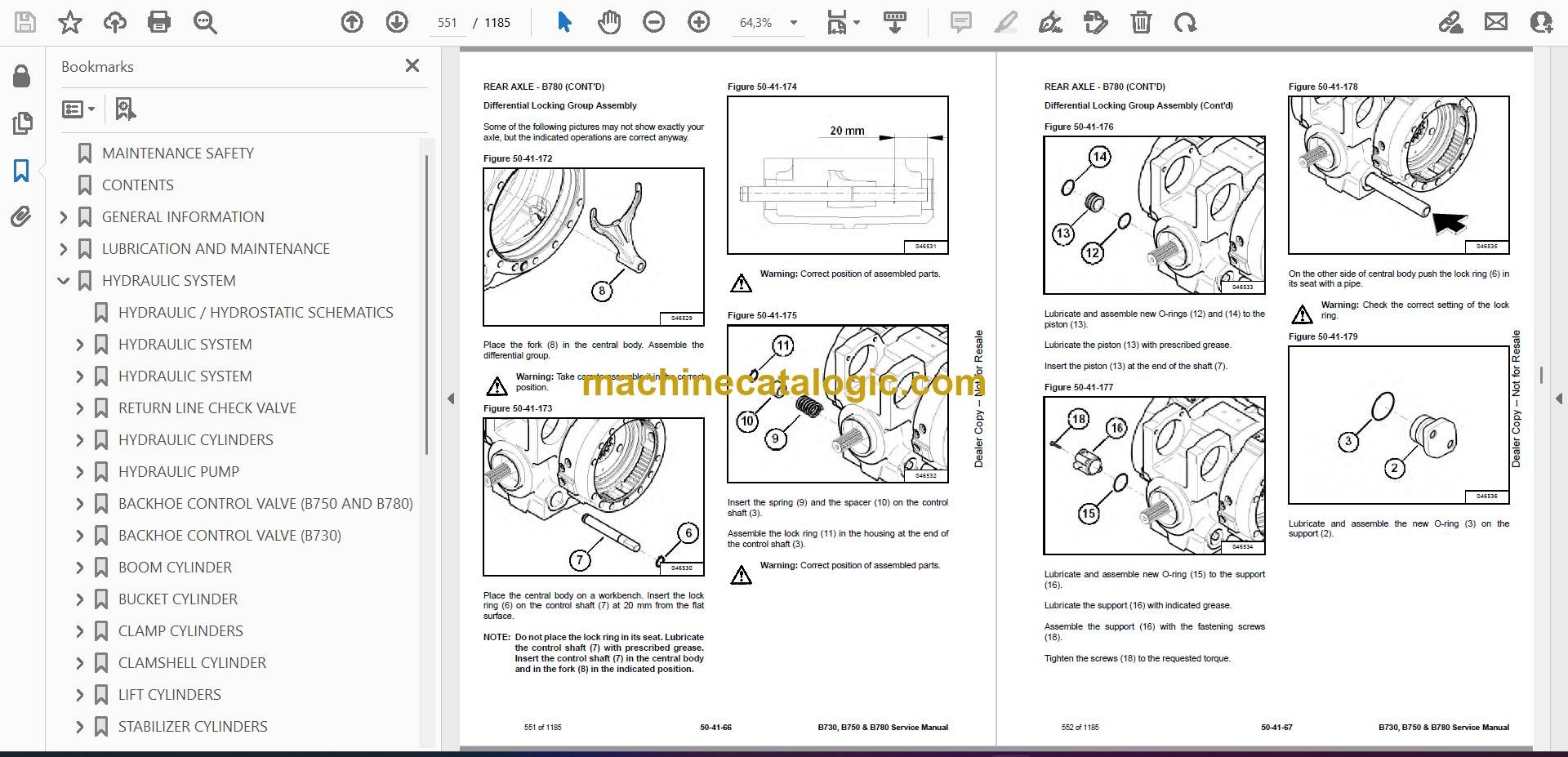
Q: Is this a searchable PDF, and can I read the wiring diagrams clearly?

A: These manuals are usually supplied as searchable PDFs, and the wiring diagrams are laid out to zoom in cleanly on a laptop or tablet.

Q: How do I know if it covers my exact B750?

A: If your serial number falls between B45211001 and B45299999, this is the correct service manual series for your machine.

Q: Is this the right document if I'm rebuilding or troubleshooting, not just changing oil?

A: Yes, this is the workshop-level service manual, meant for diagnostics, teardown, and reassembly, not routine daily checks.

Bottom line: If you own or service a Bobcat B750 backhoe loader in the B45211001-B45299999 range and you're doing real repair work, this is the right manual. If you just need how to run it, skip this and get the operator's book.

📘 Show Index

Table of Contents:

  • MAINTENANCE SAFETY
  • CONTENTS
  • GENERAL INFORMATION
    • MACHINE INFORMATION
      • B730 Specification
      • B750 Specification
      • B780 Specification
    • TECHNICAL PROPERTIES
      • B730 Specifications
      • Engine
      • Electrical System
      • Hydraulic System
      • Transmission
      • Axle / Brakes
      • Tires
      • Loader
      • Backhoe
      • Cab / Canopy
      • Steering
      • Capacities
      • Weights
      • B750 Specifications
      • Engine
      • Electrical System
      • Hydraulic System
      • Transmission
      • Axle / Brakes
      • Tires
      • Loader
      • Backhoe
      • Cab / Canopy
      • Steering
      • Capacities
      • Weights
      • B780 Specifications
      • Engine
      • Electrical System
      • Hydraulic System
      • Transmission
      • Axle / Brakes
      • Tires
      • Loader
      • Backhoe
      • Cab / Canopy
      • Steering
      • Capacities
      • Weights
    • POSITION OF MACHINE
      • Loader Attachment Position
      • Backhoe Attachment Position
    • SAFETY INSTRUCTION
      • General Safety Information
      • Crushing And Burning Prevention
      • Fire And Explosion Prevention
      • Hydraulic Lines And Hoses
    • STORAGE
      • Preparing The Machine For Storage
      • Preparing The Machine For Work After A Long Period Of Storage
  • LUBRICATION AND MAINTENANCE
    • LIFTING AND BLOCKING THE BACKHOE LOADER
      • Procedure
    • APPROVED LIFT ARM SUPPORT DEVICE
      • Description
    • TOWING THE BACKHOE LOADER
      • Procedure
    • AXLE TOE-IN ADJUSTMENT
      • Procedure
    • LUBRICATION
      • General Safety Information
      • Fluids, Lubricants And Fuel
      • Lubricant And Operating Materials Specifications
      • Diesel Fuel
      • Engine Coolant
      • Hydraulic / Hydrostatic Fluid Chart
      • Brake Oil (For B730 S/N B45111001 – B45111554, B750 S/N B45211001 – B45211079 And B780 S/N B45311001 – B45311061)
      • Transmission Fluid
      • Front Axle Oil
      • Rear Axle Oil
      • Lubrication Chart (B730 And B750)
      • Lubrication Chart (B780)
      • Diesel Engine
      • Checking The Engine Oil Level
      • Draining The Engine Oil
      • Replace The Oil Filter Element
      • Adding Engine Oil
      • Cooling System
      • Checking The Coolant Level
      • Checking The Coolant Level (Cont’d)
      • Changing The Coolant
      • Draining Coolant
      • Clean The Radiator And Adding Coolant
      • Clean The Oil Cooler And The Radiator
      • Hydraulic System
      • Check Hydraulic Oil Level
      • To Drain Oil
      • To Replace The Return Filter
      • Replacing The Internal Hydraulic Filter
      • To Clean The Suction Strainer
      • Adding Hydraulic Oil
      • The Fuel System
      • Fuel Specifications
      • Biodiesel Blend Fuel
      • Drain The Contaminant From The Fuel Filter
      • Drain The Contaminant From The Fuel Tank
      • Replace The Fuel Filter Elements
      • Adding Fuel
      • Transmission System
      • Checking Transmission Oil Level
      • Draining Transmission Oil
      • Replace The Transmission Filter Elements
      • Add Transmission Oil
      • Front Drive Axle And Reduction Gears
      • To Drain Oil
      • To Add Oil
      • Reduction Gears
      • To Check Reduction Gear Oil Level
      • To Drain Reduction Gear Oil
      • Adding Reduction Gear Oil
      • Rear Axle
      • Checking Rear Axle Oil Level
      • Cleaning The Rear Axle Breather
      • Draining Rear Axle Oil
      • Adding Rear Axle Oil
      • Brake Fluid
      • Checking Brake Fluid Reservoir Level
      • Adding Brake Fluid
      • Bleeding The Brake System
    • MAINTENANCE AND ADJUSTMENTS
      • Service Schedule (B730 & B750)
      • Service Schedule (B780)
    • AIR CLEANER SERVICE
      • Engine Air Intake System
      • Cleaning The Primary Element
      • Replacing The Air Filter Elements
      • Cab Air Intake Filter
    • BACKHOE BOOM / SWING LOCK
      • Engaging And Disengaging
    • ENGINE ALTERNATOR / FAN BELT AND AIR CONDITIONER BELT (IF EQUIPPED)
      • Maintenance Instruction
      • Replacing Fan And Alternator Belt
    • TIRE MAINTENANCE
      • Type Of Tires
      • To Replace A Wheel
      • Wheel Nut Torque Settings
    • LUBRICATING THE BACKHOE LOADER
      • Lubrication Locations
  • HYDRAULIC SYSTEM
    • HYDRAULIC / HYDROSTATIC SCHEMATICS
    • HYDRAULIC SYSTEM
      • Glossary Of Hydraulic / Hydrostatic Symbols
    • HYDRAULIC SYSTEM
      • Tests And Hydraulic Pressure Test (B730)
      • Tests And Hydraulic Pressure Test (B750)
      • Tests And Hydraulic Pressure Test (B780)
      • Test Ports
      • Hydraulic Tank And Return Filter
      • Fixed Displacement Tandem Pump
      • Blocks
      • ON-OFF Solenoid Valve
      • ON-OFF Pressure Reducing Valve
      • Loader Control Valve
      • Unloading Valve Test
      • Steering Priority Valve
      • Backhoe Control Valve
      • Steering Pressure Test
      • Pilot Pressure Test (B750) And (B780)
      • Pilot Pressure Regulation Block (B780)
      • Pilot Pressure Regulation Block (B750)
      • Priority Valve (B730 And B750)
      • Priority Valve (B780)
    • RETURN LINE CHECK VALVE
      • Removal And Installation
    • HYDRAULIC CYLINDERS
      • Basic Type Cylinder Assembly
      • Nut Type Cylinder Montage
      • Loader Lift Cylinder
      • Loader Bucket (Tilt) Cylinder
      • Clampshell Cylinder
      • Backhoe Boom Cylinder
      • Backhoe Arm Cylinder
      • Backhoe Bucket Cylinder
      • Backhoe Extendible Arm Cylinder
      • Backhoe Swing Cylinder
      • Backhoe Stabilizer Cylinder
    • HYDRAULIC PUMP
      • Removal And Installation (B780)
      • Removal And Installation (B730 AND B750)
    • BACKHOE CONTROL VALVE (B750 AND B780)
      • Removal And Installation
    • BACKHOE CONTROL VALVE (B730)
      • Removal And Installation
    • BOOM CYLINDER
      • Removal And Installation
    • BUCKET CYLINDER
      • Removal And Installation
    • CLAMP CYLINDERS
      • Removal And Installation
    • CLAMSHELL CYLINDER
      • Removal And Installation
    • LIFT CYLINDERS
      • Removal And Installation
    • STABILIZER CYLINDERS
      • Removal And Installation
    • STICK CYLINDER
      • Removal And Installation
    • SWING CYLINDERS
      • Removal And Installation
    • TILT CYLINDERS (b750 AND b780)
      • Removal And Installation
    • TILT CYLINDERS (b730)
      • Removal And Installation
    • BRAKE PEDAL AND BOOSTER
      • Removal And Installation (B730 S/N B4511155 & Above) (B750 S/N B45211080 & Above) (B780 S/N B45311062 & Above)
    • HYDRAULIC RESERVOIR
      • Removal And Installation
    • LOADER CONTROL VALVE (B750 AND B780)
      • Removal And Installation
    • LOADER CONTROL VALVE (B730)
      • Removal And Installation
    • STEERING COLUMN AND UNIT
      • Removal And Installation
  • ELECTRICAL SYSTEM
    • ELECTRICAL SCHEMATICS
    • ELECTRICAL SYSTEM
      • Fuses – B730 And B750
      • Relays – B730 And B750
      • Fuses – B780
      • Relays – B780
      • Relays – B780
    • ELECTRICAL SYSTEM
      • Component Location
      • Component Location – ZF In B730 And B750
      • Component Location – Carraro In B780
    • BATTERY
      • Removal And Installation
    • FUSE
      • Fuse Location
    • RELAY
      • Relay Location
    • INSTRUMENT CLUSTERS
      • Removal And Installation
  • AXLES
    • SAFTEY INSTRUCTIONS
      • General Safety Recommendations
    • FRONT AXLE – B730 AND B750
      • Description
      • Removal And Installation
      • Disassembly
      • Reassembly
    • FRONT AXLE – B780
      • Description
      • Removal And Installation
      • Tightening Torque
      • Steering Cylinder Group Disassembly
      • Steering Cylinder Group Assembly
      • Epicyclic Reduction Gear Group Disassembly
      • Epicyclic Reduction Gear Group Assembly
      • Wheel Hub Group Disassembly
      • Wheel Hub Group Assembly
      • Axle Beam Group Disassembly
      • Axle Beam Group Assembly
      • Flange Group Disassembly
      • Flange Group Assembly
      • Differential Support Group Disassembly
      • Differential Support Group Assembly
      • Differential Group Disassembly
      • Differential Group Assembly
      • Pinion Group Disassembly
      • Pinion Group Assembly
      • Toe-in / Steering Angle
      • Steering Angle Adjustment
      • Testing After Assembly
    • FRONT SHAFT – B780
      • Removal And Installation
    • REAR SHAFT – B780
      • Removal And Installation
    • FRONT SHAFT B730 AND B750
      • Removal And Installation
    • REAR SHAFT – B730 AND B750
      • Removal And Installation
    • SAFETY INSTRUCTIONS
      • General Safety Recommendations
    • REAR AXLE – B730 AND B750
      • Preface
      • Lubrication And Maintenance Instructions
      • Service Brake – Brake Wear Measurement On The ZF- Axle MT-B 3070
      • Instructions For The Displacement Resp. Emergency Towing Of The Vehicle
      • Technical Data
      • Removal And Installation
      • Disassembly – Output Unit
      • Service Brake (Multi-Disc Brake)
      • Differential
      • Disassembly – Input
      • Disassembly – Parking Brake (Multi-Disc Brake)
      • Disassembly – Parking Brake (Disc Brake)
      • Reassembly – Input
      • Reassembly – Differential
      • Assembly Service Brake (Multi-Disc Brake)
      • Reassembly – Output Unit
      • Parking Brake Version (Multi-Disc Brake)
      • Reassembly of Parking Brake version (Disc Brake)
      • Completion Of Axle
    • REAR AXLE – B780
      • Description
      • Removal And Installation
      • Tightening Torque
      • Steering Cylinder Group Disassembly
      • Steering Cylinder Group Assembly
      • Epicyclic Reduction Gear Group Disassembly
      • Epicyclic Reduction Gear Group Assembly
      • Wheel Hub Group Disassembly
      • Wheel Hub Group Assembly
      • Parking Brake Group Disassembly
      • Parking Brake Group Assembly
      • Parking Brake Caliper
      • Axle Beam Trumpet Group Disassembly
      • Axle Beam Trumpet Group Assembly
      • Brake Group
      • Brake Group Disassembly
      • Brake Group Assembly
      • Differential Support Group Disassembly
      • Differential Support Group Assembly
      • Differential Group Disassembly
      • Differential Group Assembly
      • Differential Lock
      • Differential Locking Group Disassembly
      • Differential Locking Group Assembly
      • Pinion Group Disassembly
      • Pinion Group Assembly
      • Toe-In / Steering Angle
      • Steering Angle Adjustment
      • Testing After Assembly
    • SERVICE BRAKE
      • Description
      • Bleeding The Brake Circuitry
      • Test Procedure
      • Brake System Troubleshooting
  • TRANSMISSION
    • MANUAL USE
      • Maintenance
      • Repair
      • Agreements And Definitions
      • Typographic Agreements
      • Measurements
      • General Description
      • Recommendations For Repair Operations
      • Transmission Installation On The Machine
    • SAFETY INSTRUCTIONS
      • General Safety Recommendations
    • TRANSMISSION – B730 AND B750
      • Serial Number Plate Location
      • Preface
      • General
      • Schematics
      • Measuring Points For Pressure Oil And Temperature
      • Solenoid / Gear Activation
      • Hydraulic Schematic
      • Removal And Installation
      • Disassembly
      • Reassembly
    • TRANSMISSION – B780
      • Component Location
      • Tightening Torque
      • Hydraulic Schematic
      • Main Hydraulic Components
      • Kinematic Scheme
      • Plugs And Filters Disassembly
      • Removal And Installation
      • Plugs And Filters Assembly
      • Torque Converter And Oil Pump Disassembly
      • Torque Converter And Oil Pump Assembly
      • Hydraulic Control Valve Disassembly
      • Hydraulic Control Valve Assembly
      • Hydraulic System Pipes Disassembly
      • Hydraulic System Pipes Assembly
      • Transmission Housing Disassembly
      • Transmission Housing Assembly
      • Shafts A – D Disassembly
      • Shafts A – D Assembly
      • Axis B Disassembly
      • Axis B Assembly
      • Axis C Disassembly
      • Axis C Assembly
      • Axis E Disassembly
      • Axis E Assembly
  • ENGINE SERVICE
    • GENERAL INFORMATION
      • Introduction
      • Engine Views
      • Engine Identification
      • Safety Precautions
      • Engine Lift Equipment
      • Viton Seals
      • POWERPART Recommended Consumable Products
    • SPECIFICATIONS
      • Basic Engine Data
      • Data And Dimensions
      • Thread Sealant
      • Standard Torque Values
      • Specific Torque Values
      • Compression Test Data
    • CYLINDER HEAD
      • General Description
      • Atomiser Cover
      • Rocker Cover
      • Rocker Arm
      • Valve Tip Clearances
      • Valve Springs
      • Removal
      • Installation
      • Valve And Valve Springs
      • Valve Guides
      • Inspection And To Correct
    • PISTON AND CONNECTING ROD ASSEMBLIES
      • General Description
      • Big End Bearing
      • Piston And Connecting Rod
      • Piston Rings
      • Piston And Connecting Rod Assembly
      • Piston And Piston Rings
      • Connecting Rod
      • Partially Finished Small End Bush
      • Piston Cooling Jets
    • CRANKSHAFT ASSEMBLY
      • General Description
      • Crankshaft Pulley
      • Rear End Oil Seal Assembly
      • To Remove And To Fit A Wear Sleeve
      • Thrust Washers
      • Main Bearings
      • Crankshaft
      • Balancer Unit
    • TIMING CASE AND DRIVE ASSEMBLY
      • General Description
      • Timing Cover
      • Mechanical Fuel Pump Gear
      • Electronic Fuel Pump Gear
      • Idler Gear and Hub
      • Heavy Duty Idler Gear
      • Camshaft Gear
      • Front Oil Seal
      • Timing Case
      • Crankshaft Gear
      • Camshaft and Tappets
    • CYLINDER BLOCK ASSEMBLY
      • General Description
      • Cylinder Block
      • Cylinder Bore
    • ENGINE TIMING
      • General Description
      • To Set Number 1 Piston To TDC On The Compression Stroke
      • To Check The Timing Of The Bosch VP30 Fuel Injection Pump
      • To Check The Timing Of The Bosch EPVE Fuel Injection Pump
      • To Adjust The Timing Of The Bosch EPVE Fuel Injection Pump
      • To Check The Timing Of The Delphi DP210 Fuel Injection Pump
      • To Check The Valve Timing
    • ASPERATION SYSTEM
      • General Description
      • Exhaust Elbow
      • Turbocharger Side Mount
      • Turbocharger Faults
      • Open Engine Breather
      • Natural Aspirated Engine Breather
      • Closed Engine Breather
    • LUBRICATION SYSTEM
      • General Description
      • Lubrication System Flow Diagram
      • Canister Type Oil Filter
      • Element Type Oil Filter
      • Filter Head
      • Sump
      • Dipstick Tube
      • Oil Strainer And Suction Pipe
      • Lubricating Oil Pump Assembly
      • Relief Valve
    • FUEL SYSTEM
      • General Description
      • Cold Start Advance Unit (KSB)
      • Typical Fuel System
      • Fuel Filter Assembly
      • Atomizers
      • Fuel Lift Pump And Filter Assembly
      • Removing Air From The Fuel System
      • Bosch VP30 Fuel Injection Pump
      • Bosch EVPE Fuel Injection Pump
      • Delphi DP210 Fuel Injection Pump
    • COOLING SYSTEM
      • General Description
      • Coolant Flow Diagram
      • Thermostat
      • Coolant Pump
      • Fan
      • Fan Drive
      • Lubricating Oil Cooler
      • Coolant Bypass Pipe
      • Oil Cooler / Radiator Removal And Installation B780
      • Oil Cooler / Radiator Removal And Installation B730 And B750
    • FLYWHEEL AND HOUSING
      • General Description
      • Flywheel
      • Ring Gear
      • Flywheel Housing
    • ELECTRICAL SYSTEM
      • General Description
      • Alternator
      • Starting Aid (Glow Plug)
      • Electrical Components
      • Engine Control Module (ECM)
      • Voltage Load Protection Module
      • Programming A New ECM
      • Speed And Timing Sensor
      • Pressure Sensor
      • Temperature Sensor
      • Wiring Harness
    • AUXILIARY EQUIPMENT
      • Power Steering Pump
      • Adaptor For A Hydraulic Pump Or A Steering Pump
      • Exhauster
    • SPECIAL TOOLS
      • List Of Special Tools
    • REAR HAND THROTTLE LEVER
      • Cable Adjustment Procedure
    • ACCELERATOR PEDAL
      • Removal And Installation
      • Cable Adjustment Procedure
    • EXHAUST
      • Removal And Installation
    • AIR FILTER
      • Housing Removal And Installation
    • ENGINE B780
      • Removal And Installation
    • ENGINE B730 AND B750
      • Removal And Installation
  • HEATING, VENTILATION AND AIR CONDITIONING (HVAC)
    • HVAC UNIT
      • Removal
      • Installation
  • MAIN FRAME
    • BACKHOE BOOM / SWING LOCK
      • Removal And Installation
    • BACKHOE BUCKET TEETH
      • Removal And Installation
    • LOADER BUCKET TEETH
      • Removal And Installation
    • BOOM
      • Removal And Installation
    • CAB (B750 AND B780)
      • Removal And Installation
    • CAB (B730)
      • Removal And Installation
    • COUNTERWEIGHT
      • Removal And Installation
    • ENGINE COVER
      • Removal And Installation
    • ENGINE SIDE COVERS
      • Removal And Installation
    • FRONT MUDGUARD (B780)
      • Removal And Installation
    • FRONT MUDGUARD (B730 AND B750)
      • Removal And Installation
    • PARKING LEVER
      • Removal And Installation
    • FUEL TANK
      • Removal And Installation
    • GRILL FRAME
      • Removal And Installation
    • GRILLE
      • Removal And Installation
    • KINGPOST
      • Removal And Installation
    • SIDE SHIFT
      • Removal And Installation
    • STICK
      • Removal And Installation
    • FRONT CONSOLE
      • Removal And Installation
    • STABILIZER WEAR PADS
      • Adjustment
  • ALPHABETICAL INDEX

Bobcat Software

Bobcat PDF Manuals

Related Manuals

0
    0
    Your Cart
    Your cart is emptyReturn to Shop