$ 0
0
$ 0
0

Bobcat BL575 Backhoe Loader Service Manual (SN 572011001-572099999)

Format: PDF (Printable Document)

File Language: English

File Pages: 666

File Size: 20.46 MB (Speed Download Link)

Brand: Bobcat

Model: BL575 Backhoe Loader

Book No: 6902022

Serial No: SN 572011001-572099999

Type of Document: Service Manual

Categories: ,

$ 45

Share:

Bobcat BL575 Backhoe Loader Service Manual (SN 572011001-572099999)

A BL575 backhoe loader is a construction-yard mule: loader up front, hoe out back, running a hydraulic system off a small diesel, doing trenching, loading trucks, and farm work. The people who reach for this service manual are the ones actually fixing things, not just running the machine. They want step-by-step tear-down and reassembly, wiring info, and the right specs so a repair only gets done once.

What this manual helps you do

  • Diagnose hydraulic problems in the loader and backhoe circuits, and trace leaks or weak functions through the system
  • Check and set pressures in the hydraulic and, where equipped, hydrostatic related systems using the correct test ports and sequences
  • Follow engine removal, disassembly, and reinstallation steps so you can do head work, bottom-end work, or full rebuilds with confidence
  • Troubleshoot electrical faults using wiring diagrams, connector callouts, and basic test procedures with a meter
  • Replace and adjust driveline, steering, and brake components so the machine tracks straight, stops right, and steers like it should

Who this is for

This is for a small contractor, farm shop, independent mechanic, or rental fleet that owns or supports a Bobcat BL575 and wants to do real repairs in-house. If you just need operating tips, safety info, or basic maintenance intervals, you want the operator's handbook instead, not this manual.

FAQ

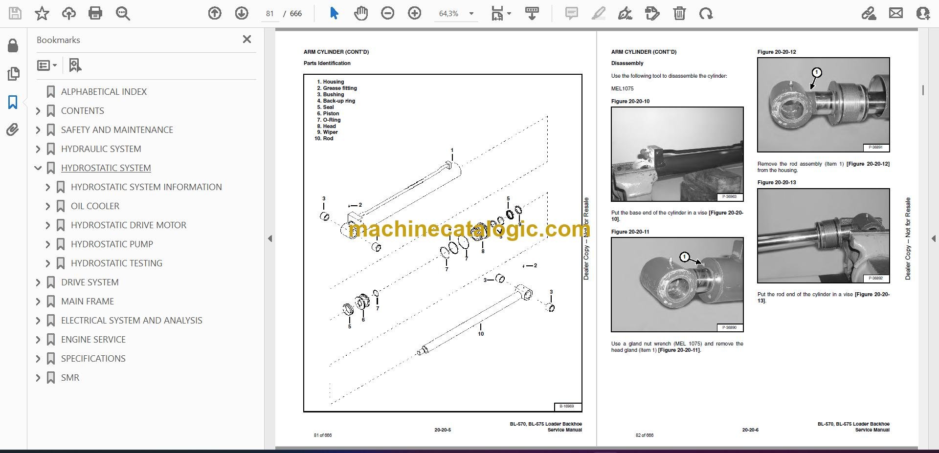
Q: Is this a searchable PDF and are the wiring diagrams readable?

A: These manuals are usually scanned or native PDFs that you can search, and wiring diagrams are laid out so you can zoom in and follow circuits.

Q: Does it cover my BL575 by serial number?

A: Yes, if your serial number falls between 572011001 and 572099999, this is the right manual. Outside that range, you need a different book.

Q: Is this the right document for doing full repairs?

A: Yes, this is the workshop service manual, meant for teardown, diagnostics, and reassembly, not just basic maintenance.

Bottom line: If you own or wrench on a BL575 in that serial range and you're doing your own repairs, this is the manual you want. If you only need to learn how to run it, skip this one.

📘 Show Index

Table of Contents:

  • ALPHABETICAL INDEX
  • CONTENTS
    • FOREWORD
    • SAFETY INSTRUCTIONS FOR INGERSOLL RAND LOADER BACKHOE AND ATTACHMENTS
      • SAFE OPERATION IS THE OPERATOR’S RESPONSIBILITY
    • FIRE PREVENTION
    • SERIAL NUMBER LOCATION
      • Loader Backhoe Serial Number
      • Engine Serial Number
    • DELIVER REPORT
    • INGERSOLL RAND IDENTIFICAITON
  • SAFETY AND MAINTENANCE
    • LIFTING AND BLOCKING THE LOADER BACKHOE
      • Procedure
    • LIFT ARM SUPPORT DEVICE
      • Installing The Lift Arm Support Device
      • Removing The Lift Arm Support Device
    • ENGINE COVER
    • TRANSPORTING THE LOADER BACKHOE
      • Procedure
    • TOWING THE LOADER BACKHOE
      • Procedure
    • AXLE TOE-IN
      • Adjustment
    • SERVICE SCHEDULE
      • Chart
    • AIR CLEANER SERVICE
      • Replacing Filter Element
    • ENGINE COOLING SYSTEM
      • Coolant Replacement
    • FUEL SYSTEM
      • Fuel Specifications
      • Filling The Fuel Tank
      • Fuel Filter
    • ENGINE LUBRICATION SYSTEM
      • Checking Engine Oil
      • Oil Chart
      • Replacing Oil And Filter
    • HYDRAULIC/HYDROSTATIC SYSTEM
      • Checking And Adding Fluid
      • Cleaning The Cooler
      • Replacing Hydraulic/Hydrostatic Filter
      • Replacing Hydraulic Fluid
    • REAR AXLE
      • Checking Oil Level
      • Draining Oil
    • FRONT AXLE
      • Checking Oil Level
      • Draining Oil
    • BACKHOE BOOM LOCK
      • Disengaging The Boom Lock
      • Engaging Boom Lock
    • BOB-TACH HAND LEVER
      • Inspection And Maintenance
    • ALTERNATOR BELT
      • Adjusting The Alternator Belt
    • LUBRICATING THE LOADER BACKHOE
    • TIRE MAINTENANCE
      • Wheel Nuts
      • Mounting
      • Tire Pressure
  • HYDRAULIC SYSTEM
    • HYDRAULIC/HYDROSTATIC SCHEMATICS
    • HYDRAULIC SYSTEM INFORMATION
      • Troubleshooting
      • Description
    • ARM CYLINDER
      • Checking
      • Removal And Installation
      • Parts Identification
      • Disassembly
      • Assembly
    • BOOM CYLINDER
      • Checking
      • Removal And Installation
      • Parts Identification
      • Disassembly
      • Assembly
    • SWING CYLINDER (WITHOUT SIDESHIFT)
      • Removal And Installation
      • Bushing Removal And Installation
      • Parts Identification
      • Disassembly
      • Assembly
    • SWING CYLINDER (WITH SIDESHIFT)
      • Removal And Installation
      • Bushing Removal And Installation
      • Parts Identification
      • Disassembly
      • Assembly
    • BUCKET CYLINDER
      • Checking
      • Removal And Installation
      • Parts Identification
      • Disassembly
      • Assembly
    • STABILIZER CYLINDER (WITHOUT SIDESHIFT)
      • Checking
      • Removal And Installation
      • Parts Identification
      • Disassembly
      • Assembly
    • STABILIZER CYLINDER (WITH SIDESHIFT)
      • Checking
      • Removal And Installation
      • Parts Identification
      • Disassembly
      • Assembly
    • TILT CYLINDER
      • Checking
      • Removal And Installation
      • Parts Identification (Left Side)
      • Parts Identification (Right Side)
      • Disassembly
      • Assembly
    • LIFT CYLINDER
      • Checking
      • Removal And Installation
      • Parts Identification (Left Side)
      • Parts Identification (Right Side)
      • Disassembly
      • Assembly
    • STEERING CYLINDER (FRONT)
      • Removal And Installation
    • STEERING CYLINDER (FRONT) (CONT’D)
      • Parts Identification
      • Disassembly And Assembly
      • Inspection
    • STEERING CYLINDER (REAR)
      • Removal And Installation
    • STEERING CYLINDER (REAR) (CONT’D)
      • Parts Identification
      • Disassembly And Assembly
      • Inspection
    • MAIN RELIEF VALVE
      • Testing The Main Relief Valve
      • Adjustment
    • PORT RELIEF VALVE (BACKHOE CONTROL VALVE)
      • Testing And Adjusting (Arm Control)
      • Testing And Adjusting (Boom Control)
      • Testing And Adjusting (Boom Swing Control)
    • PORT RELIEF VALVE (LOADER CONTROL VALVE)
      • Testing And Adjusting (Bucket Tilt)
      • Testing And Adjusting (Front Auxiliary)
    • LOADER CONTROL VALVE
      • Removal And Installation
      • Parts Identification
      • Disassembly And Assembly
      • Inlet/Outlet Valve Section
      • Lift Arm Valve Section
      • Tilt Valve Section
      • Auxiliary Valve Section (Front)
      • Auxiliary Valve Section (Rear) (Optional)
    • BACKHOE CONTROL VALVE
      • Removal And Installation
      • Parts Identification
      • Disassembly And Assembly
      • Inlet/Outlet Valve Section
      • Arm Valve Section
      • Tilt Valve Section
      • Right Stabilizer Valve Section
      • Left Stabilizer Valve Section
      • Boom Valve Section
      • Boom Swing Valve Section
      • Outlet Valve Section
    • HYDRAULIC FLUID RESERVOIR
      • Removal And Installation
      • Strainer Removal And Installation
    • HYDRAULIC FILTER HOUSING
      • Removal And Installation
      • Disassembly
      • Assembly
    • HYDRAULIC FILTER
      • Removal And Installation
    • GEAR PUMP
      • Removal And Installation
      • Parts Identification
      • Disassembly And Assembly
      • Inspection
    • STEERING PUMP
      • Removal And Installation
      • Parts Identification
      • Disassembly
      • Inspection
      • Assembly
    • STEERING VALVE
      • Removal And Installation
      • Adjustment
    • MASTER CYLINDER
      • Removal And Installation
      • Parts Identification
      • Disassembly And Assembly
  • HYDROSTATIC SYSTEM
    • HYDROSTATIC SYSTEM INFORMATION
      • Troubleshooting Chart
      • Replenishing Valve Function
    • OIL COOLER
      • Disassembly
      • Inspection
      • Assembly
    • HYDROSTATIC DRIVE MOTOR
      • Removal And Installation
      • Parts Identification
      • Disassembly
      • Disassembly
      • Inspection
      • Assembly
    • HYDROSTATIC PUMP
      • Removal And Installation
      • Parts Identification
      • Disassembly
      • Inspection
      • Assembly
    • HYDROSTATIC TESTING
      • Pump Adjustment
  • DRIVE SYSTEM
    • TROUBLESHOOTING
      • Chart
    • PARKING BRAKE
      • Lever Removal And Installation
      • Cable Removal And Installation
      • Adjustment
    • PARKING BRAKE HOUSING
      • Removal And Installation
      • Parts Identification
      • Disassembly And Assembly
    • SERVICE BRAKE
      • Description
      • Bleeding The Brake Circuit
    • REAR AXLE
      • Removal
      • Installation
    • FRONT AXLE
      • Removal
      • Installation
      • Axle Pivot Bushing Removal And Installation
    • DRIVESHAFT
      • Removal And Installation
    • DROP BOX
      • Removal And Installation
      • Parts Identification
      • Disassembly
      • Inspection
      • Assembly
    • BRAKE PEDAL ASSEMBLY
      • Removal And Installation
  • MAIN FRAME
    • OPERATOR CANOPY
      • Removal And Installation
    • ENCLOSED CAB
      • Not Available At Time Of Printing
    • OPERATOR SEAT
      • Removal And Installation
    • FLOOR PANELS
      • Front Panel Removal And Installation
      • Rear Panel Removal And Installation
      • Front Right Panel Removal And Installation
      • Front Left Panel Removal And Installation
    • GRILL
      • Removal And Installation
    • GRILL FRAME
      • Removal And Installation
    • ENGINE SIDE COVERS
      • Removal And Installation
    • FENDER
      • Removal And Installation
    • ENGINE COVER
      • Removal And Installation
    • FUEL TANK
      • Removal And Installation
      • Screen Removal And Installation
    • LIFT ARMS
      • Removal And Installation
    • BOB-TACH
      • Removal And Installation
      • Bob-Tach Lever And Wedge
      • Pivot Pin Bushing Removal And Installation
    • ARM
      • Removal And Installation
      • Arm Pivot Bushing Removal And Installation
    • BOOM (WITH SIDE SHIFT)
      • Removal And Installation
    • BOOM (WITHOUT SIDE SHIFT)
      • Removal And Installation
    • SWING FRAME (with side shift)
      • Removal And Installation
      • Bushing Removal And Installation
    • SWING FRAME (WITHOUT SIDE SHIFT)
      • Removal And Installation
    • X-CHANGE™
      • Removal And Installation
    • BUCKET
      • Backhoe Bucket Teeth Removal And Installation
      • Loader Bucket Teeth Removal And Installation
    • LIFT ARM STABILIZER
      • Removal And Installation
    • CENTER FLOOR PANEL
      • Removal And Installation
    • STABILIZER (WITHOUT SIDESHIFT)
      • Removal And Installation
  • ELECTRICAL SYSTEM AND ANALYSIS
    • ELECTRICAL SCHEMATICS
    • ELECTRICAL SYSTEM INFORMATION
      • Troubleshooting Chart
      • Description
      • Fuse Location
      • Relay Location
    • BATTERY
      • Removal And Installation
      • Servicing The Electrical System
      • Using A Booster Battery (Jump Starting)
    • ALTERNATOR
      • Adjusting The Alternator Belt
      • Description
      • Tests
      • Alternator Output Test
      • Full Field Test
      • Alternator Regulator Test
      • Alternator Regulator Test With Voltmeter
      • Removal And Installation
      • Parts Identification
      • Pulley Removal And Installation
      • Disassembly And Assembly
      • Rotor Continuity Test
      • Stator Continuity Test
      • Rectifier Continuity (Diode) Test
      • Brush Length
    • STARTER
      • Removal And Installation
      • Checking The Starter In The Loader
      • Parts Identification
      • Disassembly
      • Inspection And Repair
      • No Load Test
      • Assembly
    • FRONT LIGHTS
      • Bulb Removal And Installation
      • Housing Removal And Installation
    • TURN INDICATOR LIGHTS (FRONT)
      • Bulb Removal And Installation
    • CAB LIGHTS
      • Bulb Removal And Installation
      • Housing Removal And Installation
    • FUEL LEVEL SENDER
      • Removal And Installation
    • INSTRUMENT PANEL
      • Removal And Installation
  • ENGINE SERVICE
    • TROUBLESHOOTING
      • Chart
    • ENGINE SPEED CONTROL
      • Removal And Installation
      • Cable Removal And Installation
    • TRAVEL PEDAL
      • Removal And Installation
    • MUFFLER
      • Removal And Installation
    • AIR CLEANER
      • Removal And Installation
    • RADIATOR
      • Removal And Installation
    • ENGINE COMPONENTS AND TESTING
      • Valve Clearance Adjustment
      • Engine Compression Checking
      • Fuel Shut-Off Solenoid Removal And Installation
      • Checking Fuel Injection Pump
      • Fuel Injection Pump Removal And Installation
      • Fuel Injection Pump Timing
      • Fuel Injector Nozzles
      • Fuel Injector Nozzles Removal And Installation
      • Fuel Injector Nozzles Check
    • ENGINE
      • Removal And Installation
      • Mount Replacement
    • RECONDITIONING THE ENGINE-V2003T-EB (TURBO)
      • Cylinder Head Removal And Installation
      • Cylinder Head Disassembly And Assembly
      • Cylinder Head Servicing
      • Cylinder Head Top Clearance
      • Checking The Valve Guide
      • Reconditioning The Valve And Valve Seat
      • Valve Spring
      • Rocker Arm And Shaft Checking
      • Timing Gearcase Cover Removal And Installation
      • Idler Gear And Camshaft Removal And Installation
      • Servicing The Camshaft
      • Servicing The Idle Gear And Shaft
      • Timing Gears Checking Backlash
      • Fuel Camshaft Removal And Installation
      • Fuel Camshaft Governor
      • Crankshaft Gear Removal And Installation
      • Oil Pump Removal And Installation
      • Oil Pump Service
      • Checking Engine Oil Pressure
      • Relief Valve
      • Piston And Connecting Rod Removal And Installation
      • Servicing The Piston And Connecting Rod
      • Connecting Rod Alignment
      • Crankshaft And Bearings Removal And Installation
      • Servicing The Crankshaft And Bearings
      • Checking The Cylinder Bore
      • Water Pump Disassembly And Assembly
    • FLYWHEEL HOUSING
      • Removal And Installation
    • FLYWHEEL
      • Removal And Installation
      • Ring Gear Removal And Installation
    • DRIVE COUPLER
      • Removal And Installation
    • TURBOCHARGER
      • Not Available At Time Of Printing
  • SPECIFICATIONS
    • LOADER SPECIFICATIONS (BL 570)
      • Loader Backhoe Dimensions
    • LOADER SPECIFICATIONS (BL 575)
      • Loader Backhoe Dimensions
      • Performance
      • Controls
      • Engine
      • Hydraulic System
      • Electrical
      • Drive System
      • Capacities
      • Tires
    • ENGINE SPECIFICATIONS
      • Fuel Injection Nozzles
      • Fuel Injection Pump
      • Cylinder Head
      • Valves
      • Valve Springs
      • Valve Timing
      • Rocker Arms
      • Camshaft
      • Cylinders
      • Tappet
      • Piston Rings
      • Pistons
      • Crankshaft
      • Oil Pump
      • Thermostat
      • Connecting Rods
      • Timing Gear
      • Cylinder Liner
      • Engine Bolt Torque
      • Grinding Specifications for the Crankshaft
    • LOADER BACKHOE TORQUE
      • Specifications
    • TORQUE SPECIFICATIONS FOR BOLTS
      • Torque For General Metric Bolts
    • HYDRAULIC/HYDROSTATIC FLUID SPECIFICATIONS
      • Specifications
    • CONVERSIONS
      • Decimal And Millimeter Equivalents
      • U.S. To Metric Conversion
  • SMR
    • Revision No: BL-570/BL-575-1
    • Revision No: BL-570/BL-575-2
    • Revision No: BL-570/BL-575-3
    • Revision No: BL-570/BL-575-4

Bobcat Software

Bobcat PDF Manuals

Related Manuals

0
    0
    Your Cart
    Your cart is emptyReturn to Shop