A CT1025 is a little workhorse for mowing, loader work, moving pallets, and pulling stuff around the place. When something quits, leaks, or starts making a new noise, the service manual is what you grab if you actually plan to tear into it over a weekend. Around my place, that's when I need wiring diagrams, hydraulic test points, and step-by-step engine or axle work, not just "how to drive it" basics.
What this manual helps you do
- Diagnose no-start, hard-start, or smoky running by following engine and fuel system checks
- Trace electrical problems using wiring diagrams to chase blown fuses, bad switches, or dead lights
- Check and adjust linkages, brakes, steering, and 3-point so they work right and wear evenly
- Rebuild or reseal hydraulic components like loader/3-point cylinders and control valves using teardown and reassembly procedures
- Troubleshoot driveline and axle issues, then replace worn bearings, seals, and gears with the right sequences and specs
Who this is for
This is for a CT1025 compact tractor with a serial number between B4VG11001 and B4VG99999, whether you're a small contractor, farm owner, or shop mechanic. If you only want operating tips, safety, or basic maintenance intervals, you want the operator's handbook instead, not this workshop manual.
FAQ
Q: Is this a searchable PDF, and can I zoom in on wiring diagrams?
A: Yes, it's typically a searchable PDF and the wiring diagrams are meant to be readable when you zoom in on a laptop or tablet.
Q: How do I know if it fits my tractor?
A: Check your serial tag. If your CT1025 serial number falls between B4VG11001 and B4VG99999, this is the right manual.
Q: Is this the right document for serious repairs?
A: Yes, this is the service manual, meant for diagnostics and repairs, not just basic maintenance instructions.
Bottom line, if your tractor is a CT1025 in that serial range and you plan to wrench on it yourself, this is the manual you want. If your serial number is outside that range, it's a no.
📘 Show Index
Table of Contents:
- FORWARD
- TABLE OF CONTENTS
- SAFETY FIRST
- For Safety
- Safety Tips
- Safety Gear
- Work Place
- Safety Instructions When
Preparing Tractor
- Avoid Fires
- Cautions When Handling the
Battery
- Cautions for High Pressure Hoses
- Use of Appropriate Tools and Equipment
- Handling of Hazardous Material
- Handling of Rotating Blade, Shaft and Driving Belt
- Prevention of Scald
- Disposal of Environmental Waste
- Cautions When Handling Tires
- Safety Decals
- GENERAL
- IDENTIFICATION NUMBER
- Tractor Serial Number Location
- Engine Serial Number Location
- Transmission Number
- DIMENSIONS
- SPECIFICATIONS
- POWER FLOW
- DRIVING SPEED
- Gear Arrangement
- Speed Ratio (Engine vs. Rear Axle)
- Rear Tire Rolling Circumference
- Calculation of Driving Speed
- Driving Speed Table
- Reverse Driving Speed
- RELATIVE SPEED RATIO OF FRONT WHEELS
- Calculation For Relative Speed Ratio Of Front Wheels
- How to Measure The Actual Rolling Circumference
- MAINTENANCE SCHEDULE CHART
- TIRES
- Specified Inflation Pressure
- Tightening Torque For Tire Bolts
- TIGHTENING TORQUE
- General Use Screws, Bolts And Nuts
- Stud Bolts
- American Standard Screws, Bolts And Nuts With UNC Or UNF Threads
- UNIT CONVERSION TABLE
- ENGINE
- ENGINE IDENTIFICATION
- Engine Decal (A)
- Engine Number (B)
- Engine Dimensions
- SPECIFICATIONS
- General Specifications
- Servicing Specifications
- TROUBLESHOOTING
- EXPLODED VIEW OF ENGINE
- Cylinder Block
- Crankshaft, Piston
- Oil Pump & Camshaft
- Timing Gear Case, Governor
- Cylinder Head, Exhaust Manifold
- Oil Pan, Rear Plate, Starting Motor
- Injection Pump, Injector
- Rocker Arm Assy
- Head Cover
- Water Pump
- NTE Components (CT1025)
- SERVICING AND OPERATING
- Engine Disassembly Order
- Disasembly And Inspection of
Main Engine Parts
- Rocker Arm Ass’y
- Cylinder Head Ass’y
- Cylinder Block
- Piston and Piston Ring
- Connecting Rod
- Connecting Rod Metal
- Bearing Holder
- Crankshaft Bearing
- Crankshaft
- Flywheel and Ring Gear
- Camshaft Ass’y
- Timing Gear
- Oil Flow
- Oil Pump
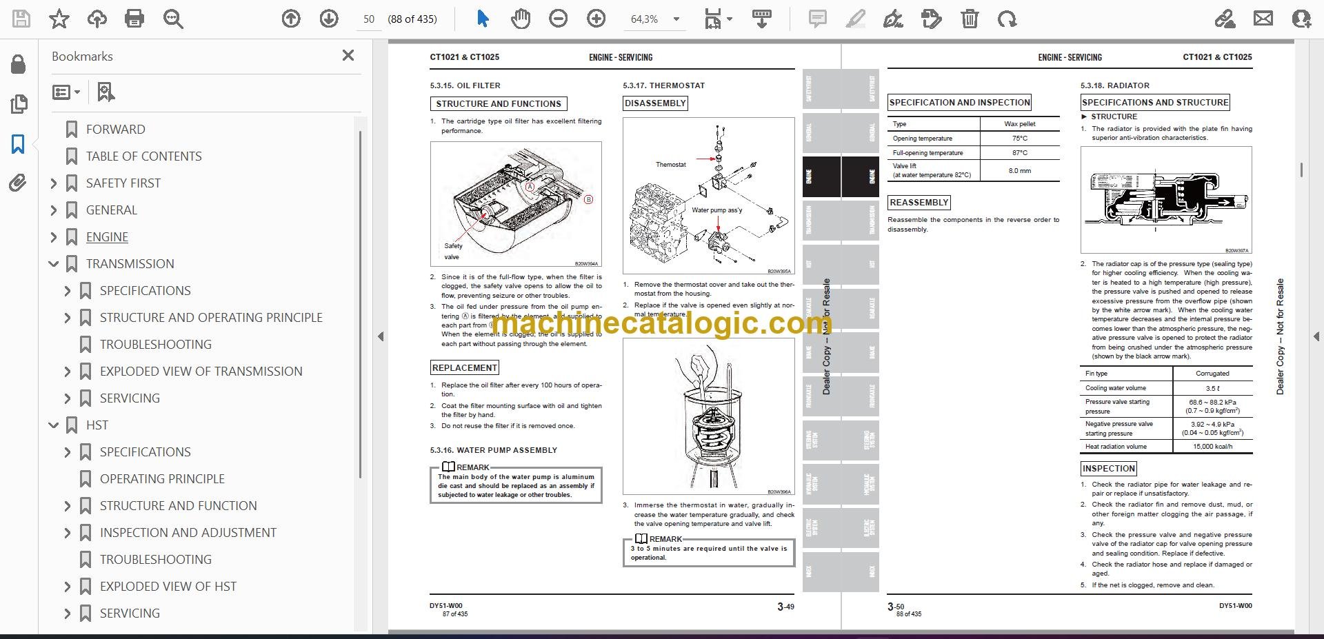
- Oil Filter
- Water pump Assembly
- Thermostat
- Radiator
- Fuel Filter
- Governor
- Injection Pump
- Nozzle and Holder
- Air Cleaner
- Reassembly
- Relief Valve Assembly with
O-ring.
- Crankshaft and Bearing
Holder Assembly.
- Oil Seal
- Rear Plate
- Flywheel
- Piston and Connecting Rod Assembly
- Suction Pipe and Suction Filter
- Oil Pan
- Oil Level Gauge and Gauge Guide
- Front Plate
- Camshaft Ass’y · Tachometer Shaft · Plate
- Idle Gear · Oil Pump Ass’y
- Timing Gear Case
- Crankshaft Pulley
- Injection Pump Assembly
- Injection Timing Adjustment
- Oil Filter
- Engine Stop Solenoid
- Tappet
- Cylinder Head
- Oil Pipe
- Push Rod and Rocker Arm Ass’y
- Valve Clearance Adjustment
- Head Cover
- Water Pump Ass’y, Radiator
Hose
- Glow Plug · Connector
- Oil Pressure Switch
- Nozzle and Holder Ass’y
- Return Pipe COMPL · Injection Pipe
- Alternator Ass’y
- Drive Gear Assembly and
Hydraulic Oil
- V Belt · Fan Pulley · Cooling fan
- Exhaust Manifold and Muffler Assembly
- ECU (Engine Control Unit) & Sensors (CT1025)
- TRANSMISSION
- SPECIFICATIONS
- General Specifications
- Tightening Torque For Major Components
- Sealant And Adhesive Specifications
- STRUCTURE AND OPERATING PRINCIPLE
- Structure
- Main Gear Shift & Shuttle System
- Range Shift Section
- PTO
- PTO Clutch Pack
- Calculation For Rear PTO And Mid PTO
- Front Wheel Drive
- TROUBLESHOOTING
- EXPLODED VIEW OF TRANSMISSION
- HI-LOW Gear
- Bevel Pinoin Gear
- PTO Gear
- 4WD Drive
- 4WD Joint
- Auto 4WD (Optional)
- SERVICING
- Transmission Removal
- FWD Case Removal
- Transmission Case Disassembly
- PTO Drive Section Disassembly
- PTO Clutch Assembly – Disassembly
- HST
- SPECIFICATIONS
- General
- HST
- Major Tightening Torque
- OPERATING PRINCIPLE
- STRUCTURE AND FUNCTION
- Power Train
- HST Components
- Major HST Component Structure And Function
- Circuit Diagram
- Pump, Motor And Swash Plate
- Charge Relief Valve
- High Pressure Relief Valve
- Inlet Check Valve (Anti-Cavitation Valve)
- Operation Of HST
- Neutral Status
- Forward Driving
- Reverse Driving
- INSPECTION AND ADJUSTMENT
- HST Neural Position Setting
- HST Forward Pedal Travel Adjustment
- Pressure Testing
- High Pressure Relief Valves
- TROUBLESHOOTING
- EXPLODED VIEW OF HST
- Main Shaft Joint
- HST Pedal
- ASSY, HST
- SERVICING
- HST Removal
- HST Components Disassembly
- REAR AXLE
- SPECIFICATIONS
- Transmission Fluid
- Tightening Torques
- OPERATING PRINCIPLE
- Power Train Of Rear Axle
- Principle Of Differential System
- Differential Lock System
- TROUBLESHOOTING
- MEASUREMENT AND ADJUSTMENT
- Backlash For Differential Pinion And Side Gear
- Pre-load Of Taper Roller Bearing On Diff
- Backlash For Spiral Bevel Pinion And Ring Gear
- Tooth Contact Of Spiral Bevel
- EXPLODED VIEW OF REAR AXLE
- G260 Rear Differential System
- G265 Rear Axle
- SERVICING
- Rear Axle Removal
- Rear Differential System Removal
- Rear Differential System Assembly Disassembly
- BRAKE
- SPECIFICATIONS
- BASIC OPERATING PRINCIPLE
- Basic Principle
- Braking Force Forward / Reverse Driving
- TROUBLESHOOTING
- INSPECTION AND ADJUSTMENT
- Brake Pedal Free Play
- Brake Switch Setting (Optional)
- Parking Brake Switch Adjustment (CT1025)
- Brake Cam Lever Free Play
- Brake Components Inspection
- EXPLODED VIEW OF BRAKE
- G250 Brake
- G418 Brake Pedal
- SERVICING
- FRONT AXLE
- SPECIFICATIONS
- General Specifications
- Sealant And Adhesive
- Tightening Torque For Major Components
- OPERATING PRINCIPLE
- Power Transfer System For Front Axle
- Differential System
- Load Transfer
- TROUBLESHOOTING
- MEASUREMENT AND ADJUSTMENT
- Toe In
- Backlash For Spiral Bevel Pinion And Spiral Bevel Gear
- Tooth Contact Of Spiral Bevel Gear
- EXPLODED VIEW OF FRONT AXLE
- Front Axle Support
- Bevel Gear Case
- Front Axle Case
- Front Axle
- SERVICING
- Front Axle Removal
- Front Axle Disassembly And
Assembly
- Steering Cylinder Removal
- Front Axle Cover Disassembly
- Bevel Gear Case Disassembly
- Front Differential System Disassembly
- Bevel Pinion Shaft Removal
- STEERING SYSTEM
- SPECIFICATIONS
- Steering Cylinder
- Steering Unit
- Tightening Torque For Main Components
- OPERATING PRINCIPLE
- Hydraulic Circuit For Steering Operation
- Operating Principle
- Structure
- TROUBLESHOOTING
- INSPECTION AND ADJUSTMENT
- Steering Relief Opening Pressure
- Relief Valve Pressure Adjustment
- EXPLODED VIEW OF STEERING SYSTEM
- G335 Steering Cylinder
- G422 Steering & Hand Accel
- G615 Power Steering Unit
- SERVICING
- Steering Cylinder
- Steering Unit Removal
- Disassembly of Power Steering Unit Components
- Inspection
- Installation
- Steering Hydraulic Tube Location
- HYDRAULIC SYSTEM
- SPECIFICATIONS
- OPERATING PRINCIPLE
- Schematic And Circuit Diagram
- Hydraulic Schematic And Basic Operation
- Components
- Hydraulic Pump
- Oil Filter
- Auxiliary Double Acting Valve (Optional)
- HPL Valve (Hyd. Power Lift)
- MOWER LIFT LINKAGE
- HYDRAULIC SCHEMATICS
- TROUBLESHOOTING
- INSPECTION AND ADJUSTMENT
- Main System Relief Valve
- Aux. Double Acting Valve Pressure
(OPTIONAL)
- Feedback Plate Adjustment
- EXPLODED VIEW OF HYDRAULIC SYSTEM
- HYD.CYLINDER
- FILTER AND PIPE
- GEAR PUMP
- CONTROL (HPL) VALVE
- DOUBLE ACTING VALVE
- REAR HYDRAULIC PIPE (Option)
- FRONT HYDRAULIC PIPE (Option)
- SHUT-OFF VALVE (Option)
- SERVICING
- Hydraulic Cylinder Removal & Disassembly
- Double Acting Valve (Optional)
Disassembly And Assembly
- Double Acting Valve Components Removal and Installation
- Gear Pump Disassembly
- Control Valve Disassembly And Assembly
- Control Valve Components Disassembly
- Assembly
- ELECTRIC SYSTEM
- ELECTRICAL SCHEMATICS
- SPECIFICATIONS
- GENERAL INFORMATION
- Battery
- Symbols For Electric Components
- Wiring Color Identification
- Fuse
- Inspection
- Cause For Blown Fuse
- Electric Device Diagnosis
- OPERATING PRINCIPLE
- When Ignition Switch Is In "OFF" Position
- When Ignition Switch Is In "ACC" Position
- When Ignition Switch Is In Turned To “ON” Position
- When Ignition Switch Is In Turned To And Held In “GL” (Manual Preheat)
Position
- When Ignition Switch Is In Turned To “ST” Position
- Operating Principle Of Preheat Controller
- ECU
- Fuse Box
- Slow-Blow Fuse
- CHECKING ELECTRIC PARTS
- Key Switch
- Combination Switch
- Flasher Unit
- 30/20A 5p Relay
- Hazard Warning Flasher Switch
- Glow Plug
- Engine Stop Solenoid (CT1021)
- ECU (CT1025)
- Actuator (CT1025)
- Pressure Sensor (CT1025)
- Speed Sensor (MPU: Magnet Pick Up)(CT1025)
- Parking Brake Micro Switch
- Brake Switch (OPTIONAL)
- Instrument Panel
- Components And Locations
- Circuit Diagram For Instrument Panel
- Gauges And Indicators
- Cluster Lamp Test
- Oil Pressure Switch
- Dual Temperature Switch
- Fuel Sensor
- Alternator
- Preheat Controller
- Neutral Safety Switch
- PTO Clutch Safety Switch
- Head Lamp
- Turn Signal Lamp
- Tail Lamp
- TROUBLESHOOTING
- When the Engine Cannot Be Started
- When the System Is Not Charged
- When the System Is Not Preheated Manually (CT1021)
- When the System Is Not Preheated Automatically
- When The Cruise System Cannot Be Operated (OPTIONAL)
- When The Head Lamp Cannot Be Operated
- Tachometer Operation With The Engine Running
- Fuel Gauge Operation
- Temperature Gauge Operation
- Hour Meter Operation
- EXPLODED VIEW OF ELECTRIC SYSTEM
- Engine Electrical System
- Transmission Electrical System
- Chassis Electrical System
- Cruise (Optional)
- Wire Harness
- Light
- Working Lamp
- INDEX
Bobcat Software
Bobcat PDF Manuals


