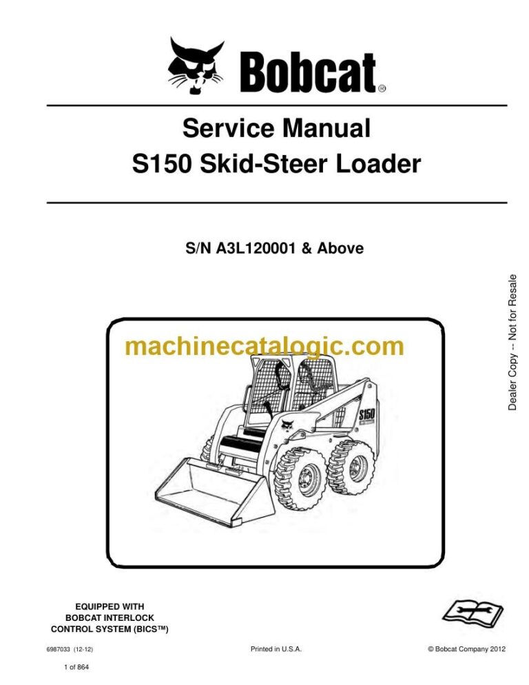
The S150 is a small skid-steer that spends its life hauling dirt, pushing snow, and running augers and forks around the farm or jobsite. When something quits, the service manual is what you grab on a Friday night so you can be back to work by Monday. It's written for people who actually turn wrenches, not just drive the machine. If your S150 falls in the serial range A3L120001 through A3L199999, this is the book you use to fix it properly.
What this manual helps you do
- Diagnose hydraulic problems, check pressures, and trace leaks in the loader and drive systems
- Follow step-by-step teardown and reassembly of the diesel engine, pumps, and drive motors
- Troubleshoot electrical issues using wiring diagrams, from dead starts to bad sensors and lights
- Adjust linkages, controls, and Bob-Tach so the machine runs straight and attachments lock correctly
- Replace seals, bearings, hoses, and other wear parts with the right order of operations and specs
Who this is for
This manual is for S150 owner-operators, small contractors, farm shops, and field techs working on that exact serial number range. If you only need basic controls, safety info, or fluid check points, you want the operator's handbook instead, not this service manual.
FAQ
Q: Is this a searchable PDF, and can I read the wiring diagrams on a laptop or tablet?
A: It's typically a PDF you can search by keyword, and the wiring diagrams are meant to be zoomed so you can follow each circuit.
Q: My S150 serial number is outside A3L120001-A3L199999. Will this still work?
A: No, you should match your loader's serial range to the correct S150 manual, or some procedures and specs may be wrong.
Q: I'm just doing routine maintenance. Is this overkill?
A: For simple oil and filter changes, yes. For real repairs, diagnostics, or rebuild work, this is the right type of document.
If your S150 serial tag falls in A3L120001 to A3L199999 and you plan to fix more than basic maintenance, then yes, this is the manual you want. Otherwise, no.
📘 Show Index
Table of Contents:
- MAINTENANCE SAFETY
- CONTENTS
- FOREWORD
- FOREWORD
- SAFETY INSTRUCTIONS
- FIRE PREVENTION
- Maintenance
- Operation
- Electrical
- Hydraulic System
- Fueling
- Starting
- Spark Arrester Exhaust System
- Welding And Grinding
- Fire Extinguishers
- SERIAL NUMBER LOCATIONS
- Loader Serial Number
- Engine Serial Number
- DELIVERY REPORT
- LOADER IDENTIFICATION
- SAFETY AND MAINTENANCE
- LIFTING AND BLOCKING THE LOADER
- LIFT ARM SUPPORT DEVICE
- OPERATOR CAB
- Description
- Raising
- Lowering
- Cab Door Sensor
- Special Applications Kit
- Special Applications Kit Inspection And Maintenance
- TRANSPORTING THE LOADER ON A TRAILER
- Loading And Unloading
- Fastening
- TOWING THE LOADER
- REMOTE START TOOL KIT -MEL1563
- Remote Start Tool – MEL1563
- Service Tool Harness Control – MEL1565
- Service Tool Harness Communicator – MEL1566
- Remote Start Procedure
- REMOTE START TOOL (SERVICE TOOL) KIT – 7217666
- Description
- Remote Start Tool (Service Tool) – 7022042
- Loader Service Tool Harness – 6689747
- Computer Service Tool Harness – 6689746
- Remote Start Procedure
- SERVICE SCHEDULE
- AIR CLEANER SERVICE
- Replacing Filter Elements
- ENGINE COOLING SYSTEM
- Cleaning
- Removing And Replacing Coolant
- Checking Level
- FUEL SYSTEM
- Fuel Specifications
- Biodiesel Blend Fuel
- Filling The Fuel Tank
- Fuel Filter
- Removing Air From The Fuel System
- ENGINE LUBRICATION SYSTEM
- Checking And Adding Engine Oil
- Engine Oil Chart
- Removing And Replacing Oil And Filter
- HYDRAULIC / HYDROSTATIC SYSTEM
- Checking And Adding Fluid
- Hydraulic / Hydrostatic Fluid Chart
- Removing And Replacing Hydraulic Fluid
- Removing And Replacing Hydraulic / Hydrostatic Filter
- Removing And Replacing Hydraulic Case Drain Filters (Single Speed Loaders)
- Removing And Replacing Hydraulic Case Drain Filters (Two-Speed Loaders)
- Removing And Replacing Hydraulic Charge Filter
- Breather Cap
- FINAL DRIVE TRANSMISSION (CHAINCASE)
- Checking And Adding Oil
- Removing And Replacing Oil
- BOB-TACH (HAND LEVER)
- Inspection And Maintenance
- BOB-TACH (POWER)
- Inspection And Maintenance
- LUBRICATING THE LOADER
- TIRE MAINTENANCE
- Wheel Nuts
- Rotating
- Mounting
- SPARK ARRESTER MUFFLER
- PIVOT PINS
- Inspection And Maintenance
- LOADER STORAGE AND RETURN TO SERVICE
- Storage
- Return To Service
- STOPPING THE ENGINE AND LEAVING THE LOADER
- EMERGENCY EXIT
- SEAT BELT
- Inspection And Maintenance
- HYDRAULIC SYSTEM
- HYDRAULIC / HYDROSTATIC SCHEMATICS
- HYDRAULIC SYSTEM INFORMATION
- Glossary Of Hydraulic / Hydrostatic Symbols
- Troubleshooting
- CYLINDER (LIFT)
- Testing
- Removal And Installation
- Parts Identification
- Disassembly And Assembly
- CYLINDER (TILT)
- Testing
- Removal And Installation
- Rod End Pivot Pin Bushing And Seal Removal And Installation
- Base End Pivot Pin Removal And Installation
- Parts Identification
- Disassembly And Assembly
- CYLINDER (BOB-TACH)
- Testing
- Removal And Installation
- Parts Identification
- Disassembly And Assembly
- MAIN RELIEF VALVE
- Description
- Testing
- Adjusting
- Removal And Installation
- HYDRAULIC CONTROL VALVE (STANDARD)
- Description
- Removal And Installation
- Identification Chart
- Mount Bracket Removal And Installation
- Lift Load Check Valve Removal And Installation
- Load Check Valve Removal And Installation (Tilt And Auxiliary)
- Anti-Cavitation Valve Removal And Installation (Lift, Rod End)
- Port Relief / Anti-Cavitation Valve Removal And Installation (Lift, Base End)
- Port Relief / Anti-Cavitation Valve Removal And Installation (Tilt, Base End)
- Port Relief / Anti-Cavitation Valve Removal And Installation (Tilt, Rod End)
- Port Relief Valve Removal And Installation
- Plug Removal And Installation
- Rubber Boot Removal And Installation
- End Cap / Spool Lock Block Removal And Installation
- Lift Spool And Detent Removal And Installation
- Tilt Spool Removal And Installation
- Auxiliary Spool Removal And Installation
- Auxiliary Solenoid Removal And Installation (S/N A3L134999 & Below)
- Auxiliary Solenoid Removal And Installation (S/N A3L135001 & Above)
- Solenoid Removal And Installation
- Lock Valve Removal And Installation
- Lift Arm Bypass Orifice Removal And Installation
- Main Relief Valve Removal And Installation
- Check Valve Removal And Installation
- HYDRAULIC CONTROL VALVE (ACS) OR (SJC)
- Description
- Removal And Installation
- Actuator Removal And Installation (Out of Loader)
- Identification Chart
- Mount Bracket Removal And Installation
- Lift Load Check Valve Removal And Installation
- Load Check Valve Removal And Installation (Tilt And Auxiliary)
- Anti-Cavitation Valve Removal And Installation (Lift, Rod End)
- Port Relief / Anti-Cavitation Valve Removal And Installation (Lift, Base End)
- Port Relief / Anti-Cavitation Valve Removal And Installation (Tilt, Base End)
- Port Relief / Anti-Cavitation Valve Removal And Installation (Tilt, Rod End)
- Port Relief Valve Removal And Installation
- Plug Removal And Installation
- End Cap Block Removal And Installation
- Lift Spool And Detent Removal And Installation
- Tilt Spool Removal And Installation
- Auxiliary Spool Removal And Installation
- Auxiliary Solenoid Removal And Installation (S/N A3L134999 & Below)
- Auxiliary Solenoid Removal And Installation (S/N A3L135001 & Above)
- Solenoid Removal And Installation
- Lock Valve Removal And Installation
- Lift Arm Bypass Orifice Removal And Installation
- Main Relief Valve Removal And Installation
- Check Valve Removal And Installation
- LIFT ARM BYPASS CONTROL VALVE
- Description
- Testing
- Removal And Installation
- Disassembly And Assembly
- HYDRAULIC PUMP (STANDARD)
- Description
- Pump Test at Quick Couplers
- Direct Pump Test (Standard Section)
- Direct Pump Test (Charge Section)
- Removal And Installation
- Hydraulic Pump Startup
- Parts Identification
- Disassembly And Assembly
- HYDRAULIC PUMP (SJC)
- Description
- Pump Test At Quick Couplers
- Direct Pump Test (Standard Section)
- Direct Pump Test (Charge Section)
- Removal And Installation
- Hydraulic Pump Startup
- Parts Identification
- Disassembly And Assembly
- HYDRAULIC / HYDROSTATIC FILTERS
- Description
- Housing Removal And Installation
- Charge Filter Housing Removal And Installation
- HYDRAULIC FLUID RESERVOIR
- Description
- Removal And Installation
- Hydraulic Fluid Screen
- OIL COOLER
- Description
- Removal And Installation
- BUCKET POSITION VALVE
- Description
- Solenoid Removal And Installation
- Solenoid Testing
- Removal And Installation
- Disassembly And Assembly
- REAR AUXILIARY DIVERTER VALVE
- Description
- Solenoid Testing
- Removal And Installation
- Disassembly And Assembly
- BOB-TACH (POWER) BLOCK
- Description
- Removal And Installation
- Disassembly And Assembly
- FRONT AUXILIARY HYDRAULIC COUPLER BLOCK
- Description
- Removal And Installation
- Disassembly And Assembly
- HYDROSTATIC SYSTEM
- HYDROSTATIC SYSTEM INFORMATION
- Troubleshooting
- Description
- HYDROSTATIC DRIVE MOTOR
- Description
- Removal And Installation
- Parts Identification
- Disassembly And Assembly
- HYDROSTATIC DRIVE MOTOR (TWO-SPEED)
- Description
- Removal And Installation (Left Side)
- Removal And Installation (Right Side)
- Parts Identification
- Disassembly
- Assembly
- HYDROSTATIC MOTOR CARRIER (SINGLE AND TWO-SPEED WITH MANUAL CONTROLS)
- Description
- Shaft Seal Removal And Installation
- Removal And Installation
- Parts Identification
- Disassembly And Assembly
- HYDROSTATIC MOTOR CARRIER (SINGLE AND TWO-SPEED WITH SJC CONTROLS)
- Description
- Shaft Seal Removal And Installation
- Removal And Installation
- Parts Identification
- Disassembly And Assembly
- CHARGE PRESSURE
- Description
- Testing (S/N A3L129999 & Below)
- Sender Removal And Installation (S/N A3L129999 & Below)
- Testing (S/N A3L130001 & Above)
- Sender Removal And Installation (S/N A3L130001 & Above)
- Adjusting
- HYDROSTATIC PUMP
- Description
- Replenishing / High Pressure Relief Valve Removal And Installation
- Removal And Installation
- Hydrostatic Pump Startup
- Parts Identification (Left Half)
- Parts Identification (Right Half)
- Disassembly
- Assembly
- HYDROSTATIC PUMP (SJC)
- Description
- Hydraulic Controller Removal And Installation
- Removal And Installation
- Hydrostatic Pump Startup
- Parts Identification
- High Pressure Relief And Bypass Valve
- Charge Relief Valve
- Disassembly And Assembly
- Mechanical Neutral Adjustment
- Hydraulic Controller Neutral Adjustment
- DRIVE BELT
- Description
- Shield Removal And Installation
- Adjusting
- Belt Removal And Installation
- Tensioner Pulley Removal And Installation
- Tensioner Pulley Parts Identification
- Tensioner Pulley Disassembly
- Tensioner Pulley Assembly
- TWO-SPEED VALVE
- Description
- Valve Removal And Installation
- Valve Disassembly And Assembly
- CASE DRAIN FILTER
- Description
- Disassembly And Assembly
- DRIVE SYSTEM
- BRAKE (SINGLE SPEED)
- Description
- Disc Removal And Installation
- BRAKE (TWO-SPEED)
- Description
- Disc Removal And Installation
- Disc Disassembly And Assembly
- DRIVE COMPONENTS
- Description
- Axle Seal Removal And Installation
- Axle, Sprocket And Bearings Removal And Installation
- Chain Removal And Installation
- CHAINCASE
- Description
- Front Cover Removal And Installation
- Center Cover Removal And Installation
- Rear Cover Removal And Installation
- MAINFRAME
- SEAT BAR
- Description
- Removal And Installation
- Disassembly And Assembly
- Compression Spring Disassembly And Assembly
- OPERATOR CAB
- Gas Cylinder Removal And Installation
- Gas Cylinder Bracket Disassembly And Assembly
- Removal And Installation
- OPERATOR SEAT
- Removal And Installation
- Seat Belt Removal And Installation
- OPERATOR SEAT (SUSPENSION)
- Removal And Installation
- Slide Rail Removal And Installation
- Seat Belt Removal And Installation
- Lower Cushion Removal And Installation
- Back Cushion Removal And Installation
- Shock Removal And Installation
- 3-Point Seat Belt Removal And Installation
- BOB-TACH (HAND LEVER)
- Description
- Removal And Installation
- Lever And Wedge Disassembly And Assembly
- Pivot Pin Bushing And Seal Removal And Installation
- BOB-TACH (POWER)
- Description
- Removal And Installation
- Lever And Wedge Disassembly And Assembly
- Pivot Pin Bushing And Seal Removal And Installation
- LIFT ARMS
- REAR GRILLE
- REAR DOOR (TAILGATE)
- Removal And Installation
- Striker Removal And Installation
- Striker Disassembly And Assembly
- Striker (Adjusting)
- Latch Removal And Installation
- FUEL TANK
- Removal And Installation
- Fuel Level Sender Removal And Installation
- Fuel Fill Screen Removal And Installation
- CONTROL PEDALS AND LINKAGES
- Description
- Pedal Removal And Installation
- Linkage Removal And Installation
- Pedal (Adjusting)
- CONTROL PEDALS (ACS)
- Description
- Foot Sensor Removal And Installation
- Foot Pedal Removal And Installation
- Foot Pedal Linkage Disassembly And Assembly
- CONTROL PANEL
- Description
- Removal And Installation
- Shock Removal And Installation
- Shaft Removal And Installation
- Shaft Disassembly And Assembly
- Linkage Removal And Installation
- Pintle Arm Disassembly And Assembly
- Linkage Neutral (Adjusting)
- Linkage Travel (Adjusting)
- CONTROL PANEL (SJC)
- Description
- Removal And Installation
- CONTROL HANDLE / LEVER
- Description
- Lever Removal And Installation
- Boot Removal And Installation
- CONTROL HANDLE / LEVER (ACS)
- Description
- Handle Sensor Removal And Installation
- Handle Removal And Installation
- Handle Disassembly And Assembly
- Lever Removal And Installation
- Boot Removal And Installation
- CONTROL HANDLE / LEVER (SJC)
- Description
- Joystick Testing
- Joystick Removal And Installation
- Joystick Mount Removal And Installation
- ACCESS PANEL (INSIDE)
- Removal And Installation (Left)
- Removal And Installation (Right)
- ACCESS PANEL (INSIDE) (SJC)
- Removal And Installation (Left)
- Removal And Installation (Right)
- WINDOW (REAR)
- Removal
- Installation (Split Molding)
- Installation (Continuous Molding)
- WINDOW (TOP)
- WINDOW (SIDE)
- WINDOW (CAB DOOR)
- Removal (Standard Window)
- Installation (Standard Window)
- Removal And Installation (Special Applications Window)
- CAB DOOR
- Description
- Removal And Installation
- Aligning
- Adjusting
- Checking Operation
- ELECTRICAL SYSTEM AND ANALYSIS
- ELECTRICAL SCHEMATICS
- ELECTRICAL SYSTEM INFORMATION
- Glossary Of Electrical Symbols
- Standard Cab Harness Connectors
- Deluxe Cab Harness Connectors
- Mainframe Harness Connectors
- Description
- Troubleshooting
- Fuse And Relay Location / Identification
- Solenoid Testing
- BATTERY
- Removal And Installation
- Servicing
- Using A Booster Battery (Jump Starting)
- ALTERNATOR
- Belt Adjustment
- Belt Replacement
- Charging System Inspection
- Alternator Voltage Testing
- Low Voltage Testing
- High Voltage Testing
- Removal And Installation
- Parts Identification
- STARTER
- Testing
- Removal And Installation
- Parts Identification
- INSTRUMENT PANELS
- Left Panel
- Standard Key Panel
- Keyless Start Panel
- Deluxe Instrumentation Panel
- Side Panel
- Front Panel
- Front Panel Removal And Installation
- Removal And Installation (Left And Right)
- Key Switch Removal And Installation
- Alarm Removal And Installation
- LIGHTS
- Front Removal And Installation
- Rear Removal And Installation
- Cab Light Removal And Installation
- BOBCAT CONTROLLER (GATEWAY AND AUXILIARY)
- Description
- Connector Identification
- Removal And Installation
- BOBCAT CONTROLLER (ACS)
- Description
- Connector And Wire Identification
- Removal And Installation
- BOBCAT CONTROLLER (SJC) (DRIVE)
- Description
- Connector Identification
- Removal And Installation
- SPEED SENSORS (SJC)
- Description
- Testing
- Removal And Installation
- DIAGNOSTIC SERVICE CODES
- Viewing Service Codes
- Service Codes List
- BOBCAT INTERLOCK CONTROL SYSTEM (BICS™)
- Description
- Inspecting The BICS™ (Engine STOPPED – Key ON)
- Inspecting Deactivation Of The Auxiliary Hydraulics System (Engine STOPPED – Key ON)
- Inspecting The Seat Bar Sensor (Engine RUNNING)
- Inspecting The Traction Lock (Engine RUNNING)
- Inspecting The Lift Arm Bypass Control
- Inspecting Deactivation Of Lift And Tilt Functions (ACS and SJC)
- Troubleshooting
- SEAT BAR SENSOR
- Description
- Troubleshooting
- Testing
- Removal And Installation
- Bobcat Interlock Control System (BICS™) Circuit Test
- TRACTION LOCK
- Description
- Troubleshooting
- Removal And Installation
- Inspecting
- CONTROL SYSTEM (ACS)
- Description
- Troubleshooting
- Handle Sensor Connector Disassembly And Assembly
- Switch Handle Removal
- Switch Handle Installation
- Actuator Connector Disassembly And Assembly
- Handle Lock Solenoid Removal And Installation
- Handle Lock Solenoid Disassembly And Assembly
- Foot Sensor Disassembly And Assembly
- Foot Lock Solenoid Removal And Installation
- ELECTRICAL / HYDRAULIC CONTROLS
- Identification Chart
- Description
- Identification Chart ACD Group 0
- Identification Chart ACD Group 1
- Identification Chart ACD Group 2
- Identification Chart ACD Group 3
- ELECTRICAL / HYDRAULIC CONTROLS (ACS)
- Identification Chart
- Description
- Identification Chart ACD Group 0
- Identification Chart ACD Group 1
- Identification Chart ACD Group 2
- Identification Chart ACD Group 3
- ELECTRICAL / HYDRAULIC CONTROLS (SJC)
- Identification Chart
- Description
- Identification Chart ACD Group 0
- Identification Chart ACD Group 1
- Identification Chart ACD Group 2
- Identification Chart ACD Group 3
- SERVICE PC (LAPTOP COMPUTER)
- Connecting Remote Start Tool
- Connecting Remote Start Tool (Service Tool)
- CALIBRATION
- Description
- Actuator Testing
- Lift And Tilt Calibration (SJC)
- Hydrostatic Pump Calibration (SJC)
- Lift And Tilt Calibration (ACS)
- STEERING DRIFT COMPENSATION
- FLYWHEEL RPM SENSOR
- CONTROL PANEL SETUP
- Right Panel Setup (Deluxe Instrumentation Panel)
- Attachment Control Information (Deluxe Instrumentation Panel)
- PASSWORD SETUP (DELUXE INSTRUMENTATION PANEL)
- Password Description
- Changing The Owner Password
- Changing The User Passwords
- Password Lockout Feature
- PASSWORD SETUP (KEYLESS START PANEL)
- Password Description
- Changing The Owner Password
- Password Lockout Feature
- MAINTENANCE CLOCK
- BACK-UP ALARM SYSTEM
- Description
- Inspecting
- Adjusting Switch Position
- Troubleshooting (Standard And ACS)
- Troubleshooting (Joystick)
- Alarm Removal And Installation
- Switch Removal And Installation
- ENGINE SERVICE
- ENGINE INFORMATION
- Description
- Specifications
- Torque Values
- Troubleshooting
- Engine Removal And Installation
- Engine Mount Replacement
- Compression – Checking
- ENGINE SPEED CONTROL
- ENGINE SPEED CONTROL (SJC)
- Removal And Installation
- Disassembly And Assembly
- MUFFLER
- AIR CLEANER
- Housing Removal And Installation
- ENGINE COOLING SYSTEM
- Radiator Removal And Installation
- Hydraulic Fan Description (S/N A3L129999 & Below)
- Hydraulic Fan Disassembly And Assembly (S/N A3L129999 & Below)
- Blower Housing Removal And Installation (S/N A3L129999 & Below)
- Fan Removal And Installation (S/N A3L129999 & Below)
- Hydraulic Fan Motor Removal And Installation (S/N A3L129999 & Below)
- Hydraulic Fan Description (S/N A3L130001 & Above)
- Hydraulic Fan Disassembly And Assembly (S/N A3L130001 & Above)
- Blower Housing Removal And Installation (S/N A3L130001 & Above)
- Fan Removal And Installation (S/N A3L130001 & Above)
- Hydraulic Fan Motor Removal And Installation (S/N A3L130001 & Above)
- Water Pump Removal And Installation
- Water Pump Disassembly And Assembly
- Thermostat Housing Removal And Installation
- Thermostat – Checking
- LUBRICATION SYSTEM
- Oil Pan Removal And Installation
- Oil Pump Removal And Installation
- Oil Pump Inspection
- Engine Oil Pressure-Testing
- FUEL SYSTEM
- Fuel Shutoff Solenoid – Checking
- Fuel Shutoff Solenoid Removal And Installation
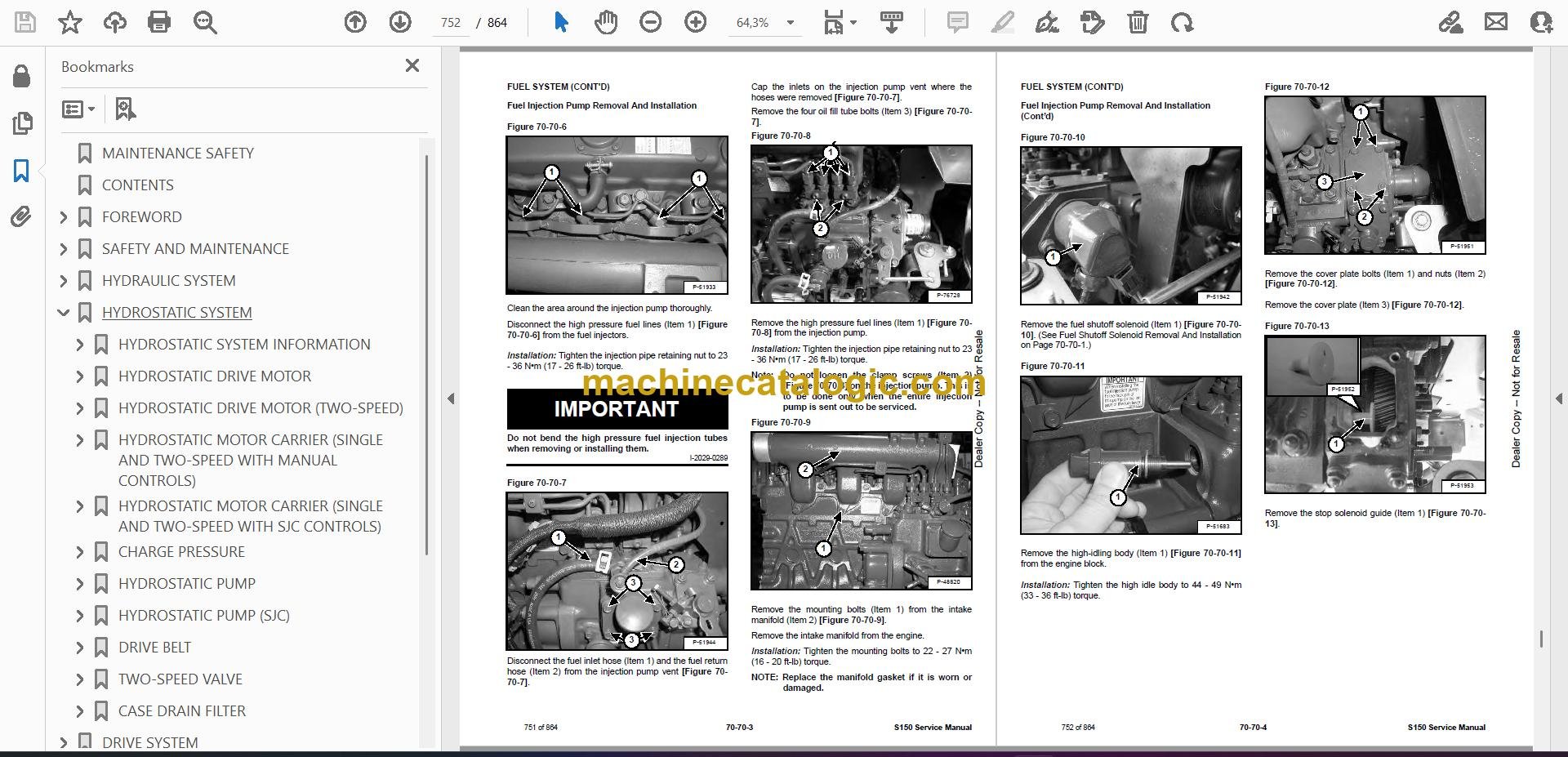
- Fuel Injection Pump – Checking
- Fuel Injection Pump Removal And Installation
- Governor Disassembly And Assembly
- Fuel Camshaft Removal And Installation
- Fuel Injection Pump – Timing
- Fuel Injector Removal And Installation
- Fuel Injector Nozzle Pressure – Checking
- Nozzle Spray Condition
- Valve Seat Tightness
- CYLINDER HEAD
- Glow Plugs – Testing
- Glow Plugs Removal And Installation
- Valve Clearance Adjustment
- Valve Timing – Checking
- Cylinder Head Removal And Installation
- Cylinder Head Disassembly And Assembly
- Cylinder Head – Servicing
- Cylinder Head Top Clearance
- Valve Guide – Checking
- Valve Guide Removal And Installation
- Reconditioning The Valve And Valve Seat
- Valve Spring
- Valve Tappets
- Rocker Arm And Shaft – Checking
- Push Rod Alignment – Checking
- CRANKSHAFT AND PISTONS
- Piston And Connecting Rod Removal And Installation
- Piston And Connecting Rod – Servicing
- Cylinder Bore – Checking
- Connecting Rod Alignment
- Crankshaft Gear Removal And Installation
- Crankshaft And Bearings Removal And Installation
- Crankshaft And Bearings – Servicing
- CAMSHAFT AND TIMING GEARS
- Timing Gearcase Cover Removal And Installation
- Timing Gears Backlash – Checking
- Idler Gear And Camshaft Removal And Installation
- Camshaft – Servicing
- Idler Gear And Shaft Servicing
- FLYWHEEL AND HOUSING
- Flywheel Removal And Installation
- Ring Gear Removal And Installation
- Housing Removal And Installation
- HEATER
- HEATER SYSTEM
- REGULAR MAINTENANCE
- TROUBLESHOOTING
- Blower Motor Does Not Operate
- Blower Motor Operators Normally, But Air Flow Is Insufficient
- Electrical System
- Engine Coolant Bypassing The Heater Valve
- Heater Valve Not Opening Or Closing
- HEATER UNIT
- HEATER COIL
- BLOWER FAN
- Removal And Installation
- Disassembly And Assembly
- Connector Identification
- HEATER VALVE
- Removal And Installation
- Disassembly And Assembly
- SPECIFICATIONS
- (S150) LOADER SPECIFICATIONS
- Machine Dimensions
- Performance
- Engine
- Drive System
- Controls
- Hydraulic System
- Electrical
- Capacities
- Tires
- TORQUE SPECIFICATIONS FOR BOLTS
- Torque For General SAE Bolts
- Torque For General Metric Bolts
- HYDRAULIC CONNECTION SPECIFICATIONS
- O-ring Face Seal Connection
- Straight Thread O-ring Fitting
- Tubelines And Hoses
- Flare Fitting
- Port Seal Fitting
- HYDRAULIC / HYDROSTATIC FLUID SPECIFICATIONS
- CONVERSIONS
- Decimal And Millimeter Equivalent Chart
- U.S. To Metric Conversion Chart
- ALPHABETICAL INDEX
- SERVICE MANUAL REVISION
- Revision No: S150 – 1
- Revision No: S150 – 2
- Revision No: S150 – 3
- Revision No: S150 – 4
- Revision No: S150 – 5
- Revision No: S150 – 6
- Revision No: S150 – 7
- Revision No: S150 – 8
- Revision No: S150 – 9
- Revision No: S150 – 10
- Revision No: S150 – 11
- Revision No: S150 – 12
- Revision No: S150 – 13
Bobcat Software
Bobcat PDF Manuals


