On a real job, an S330 is your big skid-steer for loading trucks, running a planer, or yanking out stumps. When it stops driving, lifts weak, or starts popping fuses, the service manual is what you grab, not the operator's book. Around my shop, I pull the service manual when I need teardown order, test ports, or torque patterns so I don't do the job twice. If you're trying to keep downtime low and avoid guessing on hydraulic or electrical work, this is the kind of manual you want.
What this manual helps you do
- Diagnose drive and lift issues by checking hydrostatic and hydraulic pressures with the correct test points and sequences
- Trace electrical faults using wiring schematics so you can chase shorts, opens, and bad grounds instead of throwing parts at it
- Follow step-by-step removal and installation for pumps, drive motors, cylinders, axles, and major loader components
- Rebuild engine and hydraulic components with the right disassembly order, inspection points, and reassembly procedures
- Adjust and verify control linkages, safety interlocks, and machine settings after repairs so the loader runs straight and safe
Who this is for
This manual is for anyone wrenching on a Bobcat S330 loader in the A02111001-A02159999 serial range: small contractors, owner-operators, shop mechanics, and rental fleets. If you just need to know how to run the machine or do basic greasing, you want the operator's handbook instead, not this service manual.
FAQ
Q: Is this a searchable PDF and are the wiring diagrams readable?
A: Yes, these manuals are typically searchable PDFs and the wiring diagrams are clear enough to zoom in and read pin numbers and wire colors.
Q: My S330 has a different serial number range, will this work?
A: No, this one is written for S330 loaders in the A02111001-A02159999 range, so you'll want the manual that matches your actual serial.
Q: I just bought a used S330 and plan to do my own repairs, is this the right book?
A: Yes, this is the workshop-level service manual, meant for full repairs, diagnostics, and rebuilds, not just basic maintenance.
Bottom line: If your S330 serial falls between A02111001 and A02159999 and you're doing your own repairs, this is the right manual. If your serial is outside that range, skip it and get the matching one.
📘 Show Index
Table of Contents:
- MAINTENANCE SAFETY
- ALPHABETICAL INDEX
- CONTENTS
- FOREWORD
- SAFETY INSTRUCTIONS
- FIRE PREVENTION
- Maintenance
- Operation
- Electrical
- Hydraulic System
- Fueling
- Starting
- Spark Arrestor Exhaust System
- Welding And Grinding
- Fire Extinguishers
- SERIAL NUMBER LOCATION
- Loader Serial Number
- Engine Serial Number
- DELIVERY REPORT
- BOBCAT LOADER IDENTIFICATION
- SAFETY AND MAINTENANCE
- LIFTING AND BLOCKING THE LOADER
- LIFT ARM SUPPORT DEVICE
- OPERATOR CAB
- Description
- Raising
- Lowering
- Cab Door Sensor
- Special Applications Kit
- Special Applications Kit Inspection And Maintenance
- TRANSPORTING THE LOADER ON A TRAILER
- Loading And Unloading
- Fastening
- TOWING THE LOADER
- REMOTE START TOOL KIT-MEL1563
- Remote Start Tool – MEL1563
- Service Tool Harness Control – MEL1565
- Service Tool Harness Communicator – MEL1566
- Remote Start Procedure
- REMOTE START TOOL (SERVICE TOOL) KIT – 6689779
- Description
- Remote Start Tool (Service Tool) – 6689778
- Loader Service Tool Harness – 6689747
- Computer Service Tool Harness – 6689746
- Remote Start Procedure
- SERVICE SCHEDULE
- AIR CLEANER SERVICE
- Replacing Filter Elements
- ENGINE COOLING SYSTEM
- Cleaning
- Removing And Replacing Coolant
- Checking Level
- FUEL SYSTEM
- Fuel Specifications
- Biodiesel Blend Fuel
- Filling The Fuel Tank
- Fuel Filter
- Removing Air From The Fuel System
- ENGINE LUBRICATION SYSTEM
- Checking And Adding Engine Oil
- Engine Oil Chart
- Removing And Replacing Oil And Filter
- HYDRAULIC / HYDROSTATIC SYSTEM
- Checking And Adding Fluid
- Hydraulic / Hydrostatic Fluid Chart
- Removing And Replacing Hydraulic Fluid
- Removing And Replacing Hydraulic / Hydrostatic Filter
- Removing And Replacing Case Drain Filters
- Removing And Replacing Hydraulic Charge Filter
- Breather Cap
- FINAL DRIVE TRANSMISSION (CHAINCASE)
- Checking And Adding Oil
- Removing And Replacing Oil
- BOB-TACH (HAND LEVER)
- Inspection And Maintenance
- BOB-TACH (POWER)
- Inspection And Maintenance
- LUBRICATING THE LOADER
- TIRE MAINTENANCE
- Wheel Nuts
- Rotating
- Mounting
- SPARK ARRESTOR MUFFLER
- PIVOT PINS
- Inspection And Maintenance
- LOADER STORAGE AND RETURN TO SERVICE
- Storage
- Return to Service
- STOPPING THE ENGINE AND LEAVING THE LOADER
- HYDRAULIC SYSTEM
- HYDRAULIC / HYDROSTATIC SCHEMATICS
- HYDRAULIC SYSTEM INFORMATION
- Glossary Of Hydraulic / Hydrostatic Symbols
- Troubleshooting
- CYLINDER (LIFT)
- Testing
- Removal And Installation
- Parts Identification
- Disassembly
- Assembly
- CYLINDER (TILT)
- Testing
- Removal And Installation
- Base End Pivot Pin Removal And Installation
- Parts Identification
- Disassembly
- Assembly
- CYLINDER (BOB-TACH)
- Testing
- Removal And Installation
- Parts Identification
- Disassembly
- Assembly
- MAIN RELIEF VALVE
- Description
- Testing
- Adjusting
- Removal And Installation
- HYDRAULIC CONTROL VALVE (STANDARD)
- Description
- Removal And Installation
- Identification Chart
- Mount Bracket Removal And Installation
- Lift Load Check Valve Removal And Installation
- Load Check Valve Removal And Installation (Tilt & Auxiliary)
- Anti-Cavitation Valve Removal And Installation (Lift, Rod End)
- Port Relief / Anti-Cavitation Valve Removal And Installation (Lift, Base End)
- Port Relief / Anti-Cavitation Valve Removal And Installation (Tilt, Base End)
- Port Relief / Anti-Cavitation Valve Removal And Installation (Tilt, Rod End)
- Port Relief Valve Removal And Installation
- Plug Removal And Installation
- Rubber Boot Removal And Installation
- End Cap Block Removal And Installation
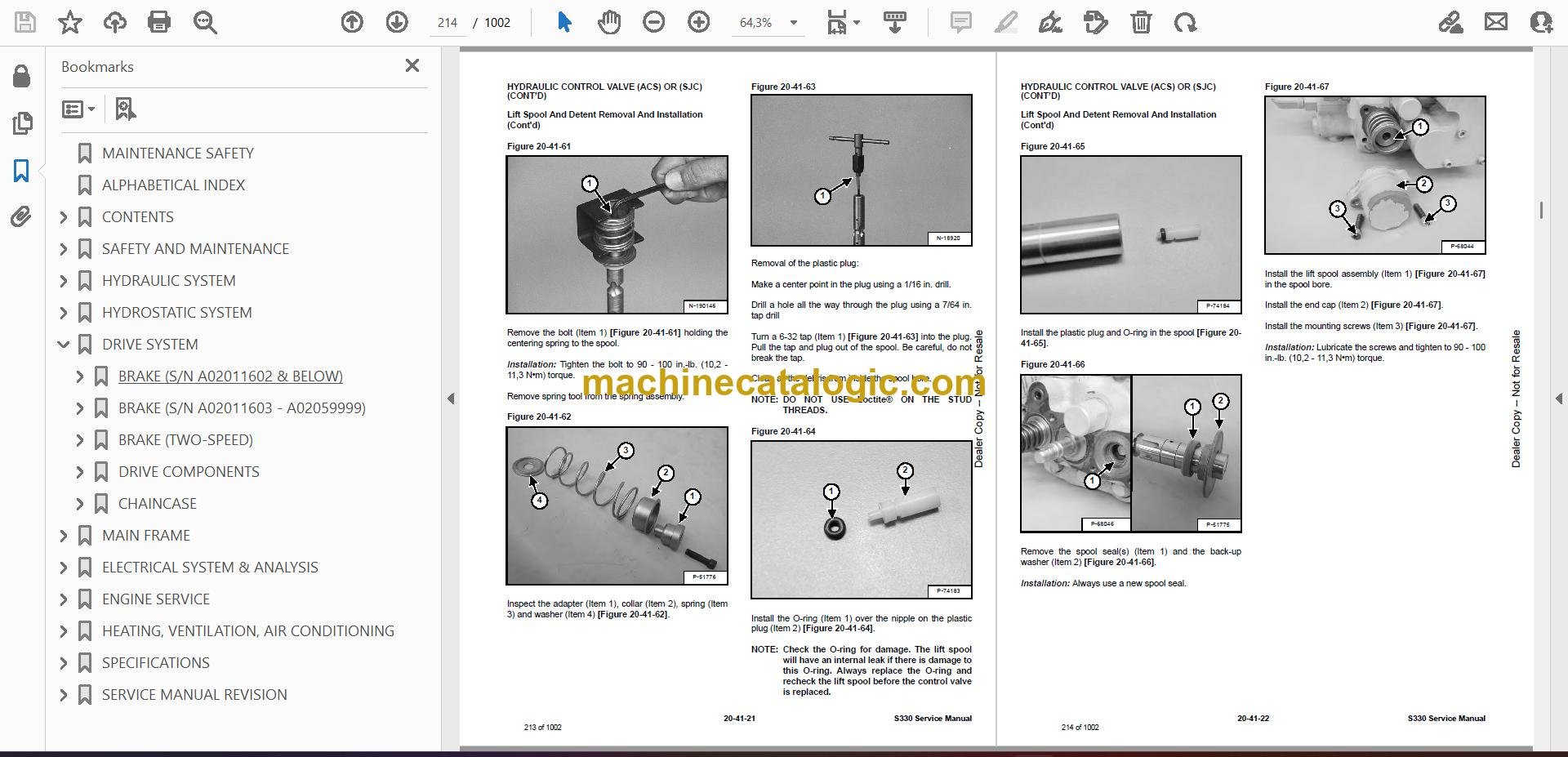
- Lift Spool And Detent Removal And Installation
- Tilt Spool Removal And Installation
- Auxiliary Spool Removal And Installation
- Auxiliary Solenoid Removal And Installation
- Solenoid Removal And Installation
- Lock Valve Removal And Installation
- Lift Arm Bypass Orifice Removal And Installation
- Main Relief Valve Removal And Installation
- Check Valve Removal And Installation
- HYDRAULIC CONTROL VALVE (ACS) OR (SJC)
- Description
- Removal And Installation
- Actuator Removal And Installation (In Loader)
- Actuator Removal And Installation (Out of Loader)
- Identification Chart
- Mount Bracket Removal And Installation
- Lift Load Check Valve Removal And Installation
- Load Check Valve Removal And Installation (Tilt & Auxiliary)
- Anti-Cavitation Valve Removal And Installation (Lift, Rod End)
- Port Relief / Anti-Cavitation Valve Removal And Installation (Lift, Base End)
- Port Relief / Anti-Cavitation Valve Removal And Installation (Tilt, Base End)
- Port Relief / Anti-Cavitation Valve Removal And Installation (Tilt, Rod End)
- Port Relief Valve Removal And Installation
- Plug Removal And Installation
- End Cap Block Removal And Installation
- Lift Spool And Detent Removal And Installation
- Tilt Spool Removal And Installation
- Auxiliary Spool Removal And Installation
- Auxiliary Solenoid Removal And Installation
- Solenoid Removal And Installation
- Lock Valve Removal And Installation
- Lift Arm Bypass Orifice Checking
- Main Relief Valve Removal And Installation
- Check Valve Removal And Installation
- LIFT ARM BYPASS CONTROL VALVE
- Description
- Testing
- Removal And Installation
- Disassembly And Assembly
- HYDRAULIC PUMP (STANDARD)
- Description
- Pump Test at Quick Couplers
- Direct Pump Test (Standard Section)
- Direct Pump Test (Charge Section)
- Removal And Installation
- Hydraulic Pump Start Up
- Parts Identification
- Disassembly And Assembly
- HYDRAULIC PUMP (STANDARD) (HIGH FLOW)
- Description
- Pump Test At Quick Couplers
- Direct Pump Test (Standard Section)
- Direct Pump Test (Charge Section)
- Direct Pump Test (High Flow Section)
- High Flow Relief Valve Adjustment
- High Flow Relief Valve Removal And Installation
- Solenoid Removal And Installation
- Removal And Installation
- Hydraulic Pump Start Up
- Parts Identification
- Disassembly And Assembly
- HYDRAULIC PUMP (SJC)
- Description
- Pump Test At Quick Couplers
- Direct Pump Test (Standard Section)
- Direct Pump Test (Charge Section)
- Removal And Installation
- Hydraulic Pump Start Up
- Parts Identification
- Disassembly And Assembly
- HYDRAULIC PUMP (SJC) (HIGH FLOW)
- Description
- Pump Test At Quick Couplers
- Direct Pump Test (Standard Section)
- Direct Pump Test (Charge Section)
- Direct Pump Test (High Flow Section)
- High Flow Relief Valve Adjustment
- High Flow Relief Valve Removal And Installation
- Solenoid Removal And Installation
- Removal And Installation
- Hydraulic Pump Start Up
- Parts Identification
- Disassembly And Assembly
- HYDRAULIC/HYDROSTATIC FILTERS
- Description
- Housing Removal And Installation
- Charge Filter Housing Removal And Installation
- HYDRAULIC FLUID RESERVOIR
- Description
- Removal And Installation
- Hydraulic Fluid Screen
- OIL COOLER
- Description
- Removal And Installation
- BUCKET POSITION VALVE
- Description
- Solenoid Removal And Installation
- Solenoid Testing
- Removal And Installation
- Disassembly And Assembly
- REAR AUXILIARY DIVERTER VALVE
- Description
- Solenoid Testing
- Removal And Installation
- Disassembly And Assembly
- BOB-TACH (POWER) BLOCK
- Description
- Removal And Installation
- Disassembly And Assembly
- FRONT AUXILIARY HYDRAULIC COUPLER BLOCK
- Description
- Removal and Installation
- Disassembly And Assembly
- HYDROSTATIC SYSTEM
- HYDROSTATIC SYSTEM INFORMATION
- Troubleshooting
- Description
- HYDROSTATIC MOTOR
- Description
- Removal And Installation
- Parts Identification
- Disassembly And Assembly
- HYDROSTATIC MOTOR (TWO-SPEED)
- Description
- Removal And Installation
- Parts Identification
- Disassembly
- Assembly
- HYDROSTATIC MOTOR CARRIER
- Description
- Removal and Installation
- Parts Identification
- Disassembly
- Assembly
- HYDROSTATIC MOTOR CARRIER (SJC)
- Description
- Removal and Installation
- Parts Identification
- Disassembly
- Assembly
- CHARGE PRESSURE
- Description
- Testing
- Sender Removal And Installation
- Adjusting
- HYDROSTATIC PUMP
- Description
- Removal And Installation
- Hydrostatic Pump Start Up
- Replenishing / High Pressure Relief Valve Removal And Installation
- Parts Identification (Left Half)
- Parts Identification (Right Half)
- Disassembly
- Assembly
- HYDROSTATIC PUMP (SJC)
- Description
- Hydraulic Controller Removal And Installation
- Removal And Installation
- Hydrostatic Pump Start Up
- Parts Identification
- High Pressure Relief And Bypass Valve
- Charge Relief Valve
- Disassembly And Assembly
- Mechanical Neutral Adjustment
- Hydraulic Controller Neutral Adjustment
- DRIVE BELT
- Description
- Drive Belt Shield Removal And Installation
- Adjusting
- Belt Removal And Installation
- Tensioner Pulley Removal And Installation
- Tensioner Pulley Tension Spring Removal And Installation
- Tensioner Pulley Tension Spring Disassembly And Assembly
- CASE DRAIN FILTER
- Description
- Disassembly And Assembly
- DRIVE SYSTEM
- BRAKE (S/N A02011602 & BELOW)
- Description
- Disc Removal And Installation
- BRAKE (S/N A02011603 – A02059999)
- Description
- Disc Removal And Installation
- BRAKE (TWO-SPEED)
- Description
- Block Removal And Installation
- Block Disassembly And Assembly
- DRIVE COMPONENTS
- Description
- Axle Seal Removal And Installation
- Axle, Sprocket And Bearings Removal And Installation
- Chain Removal And Installation
- CHAINCASE
- Description
- Front Cover Removal And Installation
- Center Cover Removal And Installation
- Rear Cover Removal And Installation
- MAIN FRAME
- SEAT BAR
- Description
- Removal And Installation
- Disassembly And Assembly
- Compression Spring Disassembly And Assembly
- OPERATOR CAB
- Gas Cylinder Removal And Installation
- Gas Cylinder Bracket Disassembly And Assembly
- Removal And Installation
- OPERATOR SEAT
- Removal And Installation
- Seat Belt Removal And Installation
- OPERATOR SEAT (SUSPENSION)
- Removal And Installation
- Slide Rail Removal And Installation
- Seat Belt Removal And Installation
- Cushion Removal And Installation
- Back Removal And Installation
- Shock Removal And Installation
- 3-Point Seat Belt Removal And Installation
- BOB-TACH (HAND LEVER)
- Description
- Removal And Installation
- Lever And Wedge Disassembly And Assembly
- Pivot Pin Bushing And Seal Removal And Installation
- BOB-TACH (POWER – OPTION)
- Description
- Removal And Installation
- Lever And Wedge Disassembly And Assembly
- Pivot Pin Bushing And Seal Removal And Installation
- LIFT ARMS
- Stabilizer Bar Removal And Installation
- Link Removal And Installation
- Removal And Installation
- REAR GRILL
- REAR DOOR
- Removal And Installation
- Striker Removal And Installation
- Striker Disassembly And Assembly
- Striker (Adjusting)
- Latch Removal And Installation
- FUEL TANK
- Removal And Installation
- Fuel Level Sender Removal And Installation
- Fuel Fill Screen Removal And Installation
- CONTROL PEDALS AND LINKAGES
- Description
- Pedal Removal And Installation
- Linkage Removal And Installation
- Pedal (Adjusting)
- CONTROL PEDALS (ACS)
- Description
- Foot Sensor Removal And Installation
- Foot Pedal Removal And Installation
- Foot Pedal Linkage Disassembly And Assembly
- CONTROL PANEL (S/N A02011250 & BELOW)
- Description
- Removal And Installation
- Shock Removal And Installation
- Shaft Removal And Installation
- Shaft Disassembly And Assembly
- Linkage Removal And Installation
- Pintle Arm Disassembly and Assembly
- Linkage Neutral (Adjusting)
- Linkage Travel (Adjusting)
- CONTROL PANEL (S/N A02011251 – A02059999, A02111001 – A02159999)
- Description
- Removal And Installation
- Shock Removal And Installation
- Shaft Removal And Installation
- Linkage Removal And Installation
- Pintle Arm Disassembly and Assembly
- Linkage Neutral (Adjusting)
- Linkage Travel (Adjusting)
- CONTROL PANEL (S/N A02011250 & BELOW) (SJC)
- Description
- Removal And Installation
- CONTROL PANEL (S/N A02011251 – A02059999, A02111001 – A02159999) (SJC)
- Description
- Removal And Installation
- CONTROL HANDLE / LEVER
- Description
- Lever Removal And Installation
- Boot Removal And Installation
- CONTROL HANDLE / LEVER (ACS)
- Description
- Handle Sensor Removal And Installation
- Handle Removal And Installation
- Handle Disassembly And Assembly
- Lever Removal And Installation
- Boot Removal And Installation
- JOYSTICK CONTROL
- Description
- Testing
- Removal And Installation
- Joystick Mount Removal And Installation
- ACCESS PANEL (INSIDE)
- Removal And Installation (Left)
- Removal And Installation (Right)
- ACCESS PANEL (INSIDE) (SJC)
- Removal And Installation (Left)
- Removal And Installation (Right)
- WINDOW (REAR)
- WINDOW (TOP)
- WINDOW (SIDE)
- WINDOW (FRONT DOOR)
- Removal (Standard Window)
- Installation (Standard Window)
- Removal And Installation (Special Applications Window)
- CAB DOOR
- Description
- Removal And Installation
- Aligning
- Adjusting
- Checking Operation
- ELECTRICAL SYSTEM & ANALYSIS
- ELECTRICAL SCHEMATICS
- ELECTRICAL SYSTEM INFORMATION
- Glossary Of Electrical Symbols
- Cab Harness Connectors
- Mainframe Harness Connectors
- Description
- Troubleshooting
- Fuse And Relay Location / Identification
- Solenoid Testing
- BATTERY
- Removal And Installation
- Servicing
- Using A Booster Battery (Jump Starting)
- ALTERNATOR
- Belt Adjustment
- Belt Replacement
- Charging System Inspection
- Alternator Voltage Testing
- Low Voltage Testing
- High Voltage Testing
- Removal And Installation
- Parts Identification
- STARTER
- Testing
- Removal And Installation
- Parts Identification
- INSTRUMENT PANELS
- Left Panel
- Right Panel (Key Switch)
- Right Panel (Keyless)
- Right Panel Setup (Keyless)
- Attachment Control Information (Keyless)
- Password Description
- Changing The Owner Password
- Changing The User Passwords
- Password Lockout Feature
- Maintenance Clock Description
- Maintenance Clock Setup
- Maintenance Clock Reset
- Side And Front Panels
- Removal And Installation (Left And Right)
- Bulb Removal And Installation (Left Only)
- Key Switch Removal And Installation
- Alarm Removal And Installation
- Front Panel Removal And Installation
- LIGHTS
- Front Removal And Installation
- Rear Removal And Installation
- Cab Light Removal And Installation
- BOBCAT CONTROLLER (MAIN)
- Description
- Connector Identification
- Removal And Installation
- BOBCAT CONTROLLER (ACS)
- Description
- Connector And Wire Identification
- Removal And Installation
- BOBCAT CONTROLLER (SJC) (DRIVE)
- Description
- Connector Identification
- Removal And Installation
- WHEEL SPEED SENSOR (SJC)
- Description
- Testing
- Removal And Installation
- DIAGNOSTIC SERVICE CODES
- Viewing Service Codes (Key Switch)
- Viewing Service Codes (Keyless)
- Service Codes List
- BOBCAT INTERLOCK CONTROL SYSTEM (BICS)
- Description
- Inspecting The BICS Controller (Engine Stopped – Key ON)
- Inspecting Deactivation Of The Auxiliary Hydraulics System (Engine STOPPED – Key ON)
- Inspecting The Seat Bar Sensor (Engine RUNNING)
- Inspecting The Traction Lock (Engine RUNNING)
- Inspecting The Lift Arm Bypass Control
- Inspecting Deactivation Of Lift And Tilt Functions
- Troubleshooting
- Troubleshooting Chart
- SEAT BAR SENSOR
- Description
- Troubleshooting
- Testing
- Removal And Installation
- Bobcat Interlock Control System (BICS) Circuit Test
- TRACTION LOCK
- Description
- Troubleshooting
- Removal And Installation (Single Speed)
- Inspecting
- CONTROL SYSTEM (ACS)
- Description
- Troubleshooting Chart
- Handle Sensor Connector Disassembly And Assembly
- Switch Handle Removal
- Switch Handle Installation
- Actuator Connector Disassembly And Assembly
- Handle Lock Solenoid Removal And Installation
- Handle Lock Solenoid Disassembly And Assembly
- Foot Sensor Disassembly And Assembly
- Foot Lock Solenoid Removal And Installation
- ELECTRICAL / HYDRAULIC CONTROLS
- ELECTRICAL / HYDRAULIC CONTROLS (SJC)
- SERVICE PC (LAPTOP COMPUTER)
- Connecting Remote Start Tool
- Connecting Remote Start Tool (Service Tool)
- CALIBRATION
- Description
- Actuator Testing
- Lift And Tilt Calibration (ACS)
- Lift And Tilt Calibration (SJC)
- Hydrostatic Pump Calibration (SJC)
- STEERING DRIFT COMPENSATION
- Description
- Selecting And Adjusting
- Exiting And Saving
- FLYWHEEL RPM SENSOR
- CONTROL PANEL SETUP
- Right Panel Setup (Keyless)
- Attachment Control Information (Keyless)
- PASSWORD SETUP (IF EQUIPPED WITH KEYLESS START)
- Password Description
- Changing The Owner And User Passwords
- Password Lockout Feature
- MAINTENANCE CLOCK
- BACK-UP ALARM SYSTEM
- Description
- Inspecting
- Adjusting Switch Position
- Troubleshooting (Standard And ACS)
- Troubleshooting (Joystick)
- Alarm Removal And Installation
- Switch Removal And Installation
- ENGINE SERVICE
- ENGINE INFORMATION
- Description
- Specifications
- Torque Values
- Troubleshooting
- Engine Removal And Installation
- Engine Mount Replacement
- Compression -Checking
- ENGINE SPEED CONTROL
- Removal And Installation
- Speed Control Cable Removal And Installation
- ENGINE SPEED CONTROL (SJC)
- Removal And Installation
- Disassembly And Assembly
- Speed Control Cable Removal And Installation
- MUFFLER
- AIR CLEANER
- Housing Removal And Installation
- ENGINE COOLING SYSTEM
- Radiator Removal And Installation
- Radiator Mount Removal And Installation
- Hydraulic Fan Motor Description (S/N A02040000 & Below, A02140000 & Below)
- Axial Fan Housing Removal And Installation (S/N A02040000 & Below, A02140000 & Below)
- Axial Fan Removal And Installation (S/N A02040000 & Below, A02140000 & Below)
- Hydraulic Fan Motor Removal And Installation (S/N A02040000 & Below, A02140000 & Below)
- Hydraulic Fan Motor Disassembly And Assembly (S/ N A02040000 & Below, A02140000 & Below)
- Hydraulic Fan Motor Description (S/N A02011251 – A02059999, A02111001 – A02159999)
- Axial Fan Housing Removal And Installation (S/N A02040001 & Above, A02140001 & Above)
- Axial Fan Removal And Installation (S/N A02011251 – A02059999, A02111001 – A02159999)
- Hydraulic Fan Motor Removal And Installation (S/N A02011251 – A02059999, A02111001 – A02159999)
- Hydraulic Fan Motor Disassembly And Assembly (S/ N A02011251 – A02059999, A02111001 – A02159999)
- Water Pump Removal And Installation
- Water Pump Disassembly And Assembly
- Thermostat Housing Removal And Installation
- Thermostat Housing Removal And Installation
- LUBRICATION SYSTEM
- Oil Pan Removal And Installation
- Oil Pump Removal And Installation
- Oil Pump Inspection
- Oil Filter Cooler Removal And Installation
- Engine Oil Pressure – Testing
- FUEL SYSTEM
- Fuel Shutoff Solenoid – Checking
- Fuel Shutoff Solenoid – Removal And Installation
- Fuel Injection Pump Assembly Removal
- Fuel Injection Pump Housing Installation
- Governor Housing Disassembly And Assembly
- Governor Disassembly And Assembly
- Fuel Camshaft Removal And Assembly
- Fuel Injection Pump Removal
- Fuel Injection Pump Installation
- Injection Pump Timing
- Fuel Injector Removal And Installation
- Fuel Injector Nozzle Pressure – Checking
- Nozzle Spraying Condition
- Valve Seat Tightness
- CYLINDER HEAD
- Intake Air Heater – Testing
- Intake Air Heater Removal And Installation
- Valve Clearance Adjustment
- Valve Timing – Checking
- Cylinder Head Removal And Installation
- Cylinder Head Disassembly And Assembly
- Cylinder Head – Servicing
- Valve Guide – Checking
- Reconditioning The Valve And Valve Seat
- Valve Spring
- Valve Tappets
- Rocker Arm And Shaft – Checking
- CRANKSHAFT AND PISTONS
- Piston And Connecting Rod Removal And Installation
- Piston And Connecting Rod – Servicing
- Cylinder Bore Checking
- Connecting Rod Alignment
- Crankshaft Gear Removal And Installation
- Crankshaft And Bearings Removal
- Crankshaft And Bearings Installation
- Crankshaft And Bearings – Servicing
- CAMSHAFT AND TIMING GEArS
- Timing Gearcase Cover Removal And Installation
- Timing Gears Backlash – Checking
- Idler Gear And Camshaft Removal and Installation
- Camshaft – Servicing
- Idler Gear And Shaft – Servicing
- TURBOCHARGER
- Description
- Testing
- Removal And Installation
- FLYWHEEL AND HOUSING
- Flywheel Removal And Installation
- Ring Gear Removal And Installation
- Housing Removal And Installation
- HEATING, VENTILATION, AIR CONDITIONING
- AIR CONDITIONING SYSTEM FLOW
- Description
- Chart
- Components
- Safety Equipment
- REGULAR MAINTENANCE
- Filter Elements Removal And Installation
- Compressor Drive Belt Inspection
- Condenser
- Air Conditioning Service Chart
- A/C Evaporator Coil & Heater Coil
- TROUBLESHOOTING
- Blower Motor Does Not Operate
- Blower Motor Operates Normally, But Air Flow Is Insufficient
- Insufficient Cooling Although Air Flow And Compressor Operation Are Normal
- The Compressor Does Not Operate At All, Or Operates Improperly
- Gauge Pressure Related Troubleshooting
- Troubleshooting Tree
- Temperature / Pressure Chart
- Poor A/C Performance
- HVAC Repair And Leaks
- Electrical System
- Engine Coolant Bypassing The Heater Valve
- Heater Valve Not Opening Or Closing
- SYSTEM CHARGING AND RECLAMATION
- Refrigerant Identification
- Reclamation And Charging With Recovery / Charging Unit
- Charging With A Manifold Gauge Set
- COMPRESSOR
- Belt Adjustment
- Removal And Installation
- Oil
- Oil Check
- Clutch Disassembly And Assembly
- CONDENSER
- RECEIVER / DRIER
- Receiver / Drier Removal And Installation
- Receiver / Drier Removal And Installation
- Pressure Relief Valve Removal And Installation
- Pressure Switch Removal And Installation
- Schraeder Valve Removal And Installation
- EVAPORATOR / HEATER UNIT
- THERMOSTAT
- EXPANSION VALVE
- EVAPORATOR COIL
- HEATER COIL
- Removal And Installation With A/C
- Removal And Installation Without A/C
- BLOWER FAN
- Removal And Installation
- Disassembly And Assembly
- Connector Identification
- HEATER VALVE
- Removal and Installation
- Disassembly And Assembly
- SPECIFICATIONS
- (S330) LOADER SPECIFICATIONS
- Dimensions
- Performance
- Controls
- Engine
- Hydraulic System
- Electrical
- Drive System
- Capacities
- Tires
- TORQUE SPECIFICATIONS FOR BOLTS
- Torque For General SAE Bolts
- Torque For General Metric Bolts
- HYDRAULIC CONNECTION SPECIFICATIONS
- O-ring Face Seal Connection
- Straight Thread O-ring Fitting
- Tubelines And Hoses
- Flare Fitting
- Port Seal Fitting
- HYDRAULIC / HYDROSTATIC FLUID SPECIFICATIONS
- CONVERSIONS
- Decimal And Millimeter Equivalents
- U.S. To Metric Conversion Chart
- SERVICE MANUAL REVISION
- Revision No: S330 – 1
- Revision No: S330 – 2
- Revision No: S330 – 3
- Revision No: S330 – 4
- Revision No: S330 – 5
- Revision No: S330 – 6
- Revision No: S330 – 7
- Revision No: S330 – 8
Bobcat Software
Bobcat PDF Manuals


