The T300 is a compact track loader that spends its life grading, loading trucks, running augers and trenchers, and pushing dirt in tight spaces. Around my shop, this service manual comes out when a machine is down, a warning light is on, or a major component is coming apart on the bench. If you're chasing a hydraulic or drive problem, doing engine work, or planning longer-term ownership of a T300 in this serial range, this is the book you want. If you just need to learn the controls, this is not it.
What this manual helps you do
- Diagnose hydraulic and hydrostatic issues, then check pressures and flows against factory specs
- Trace electrical faults, read wiring diagrams, and troubleshoot sensors, switches, and safety circuits
- Follow step-by-step removal and installation for pumps, drive motors, cylinders, and major linkages
- Rebuild and adjust engine and drivetrain components with the correct sequences and tightening patterns
- Set, verify, and fine-tune items after repair so the loader runs straight, lifts correctly, and starts reliably
Who this is for
This manual is for owners and shops working on a Bobcat T300 track loader with serial numbers from 525411001 to 525499999. It fits small contractors, rental fleets, and owner-operators who do their own repairs. If you only want operating tips or basic maintenance like greasing and fluid checks, you need the operator's handbook instead.
FAQ
Q: Is this a searchable PDF with readable wiring diagrams?
A: Yes, these manuals are usually scanned or native PDFs you can search, and the wiring diagrams are laid out so you can zoom in to follow circuits.
Q: How do I know if it covers my exact T300?
A: Check your serial plate. If your T300 serial falls between 525411001 and 525499999, this is the correct service manual.
Q: Is this the right manual if I'm just doing filters and oil?
A: It will cover that, but it's overkill. This is a workshop repair manual, not a quick maintenance checklist.
Bottom line: If your T300's serial number is in that range and you're doing real repair work, this is the right service manual. If not, you should look for a different serial range or the operator's manual.
📘 Show Index
Table of Contents:
- MAINTENANCE SAFETY
- ALPHABETICAL INDEX
- CONTENTS
- FOREWORD
- SAFETY INSTRUCTIONS
- SERIAL NUMBER LOCATION
- Loader Serial Number
- Engine Serial Number
- DELIVERY REPORT
- LOADER IDENTIFICATION
- SAFETY AND MAINTENANCE
- LIFTING AND BLOCKING THE LOADER
- LIFT ARM SUPPORT DEVICE
- Installing The Lift Arm Support Device
- Removing The Lift Arm Support Device
- OPERATOR CAB
- Description
- Raising The Operator Cab
- Lowering The Operator Cab
- Emergency Exit
- TRANSPORTING THE BOBCAT LOADER
- TOWING THE LOADER
- REMOTE START
- Procedure For Loader W/O Attachments Control Harness
- Procedure For Loader With Attachments Control Harness
- Procedure
- SERVICE SCHEDULE
- AIR CLEANER SERVICE
- ENGINE COOLING SYSTEM
- Cleaning Cooling System
- Checking The Coolant Level
- Adding The Coolant
- FUEL SYSTEM
- Fuel Specifications
- Filling The Fuel Tank
- Fuel Filter
- Removing Air From The Fuel System
- ENGINE LUBRICATION SYSTEM
- Checking Engine Oil
- Oil Chart
- Replacing Oil And Filter
- HYDRAULIC/HYDROSTATIC SYSTEM
- Checking And Adding Fluid
- Hydraulic Fluid Chart
- Hydraulic/Hydrostatic Filter Replacement
- Replacing Hydraulic Fluid And Case Drain Filters
- FAN GEARBOX
- POWER BOB-TACH
- Inspection And Maintenance
- BOB-TACH
- Inspection And Maintenance
- POWER BOB-TACH
- Inspection And Maintenance
- LUBRICATING THE LOADER
- HYDRAULIC SYSTEM
- HYDRAULIC/HYDROSTATIC SCHEMATICS
- HYDRAULIC SYSTEM INFORMATION
- Troubleshooting
- Tightening Procedure
- CYLINDER (LIFT)
- Checking
- Removal And Installation
- Parts Identification
- Disassembly
- Assembly
- CYLINDER (TILT)
- Checking
- Removal And Installation
- Base Pin Removal And Installation
- Parts Identification
- Disassembly
- Assembly
- CYLINDER (POWER BOB-TACH)
- Checking
- Removal And Installation
- Parts Identification
- Disassembly
- Assembly
- MAIN RELIEF VALVE
- Checking Main Relief
- Adjustment
- Removal and Installation
- HYDRAULIC CONTROL VALVE (2 PIECE CASTING) (FOOT CONTROL)
- Identification
- Removal And Installation
- BICS™ Valve, Removal And Installation
- BICS™ Valve, Lift Arm By-Pass Orifice Removal And Installation
- BICS™ Valve, Check Valve Removal And Installation
- Backslide, Lock Valve Removal And Installation
- BICS™ Valve, Solenoid Removal And Installation
- BICS™ Valve, Solenoid Testing
- Identification Chart
- Load Check Valve
- Main Relief Valve
- Port Relief Valve, Tilt Spool
- Port Relief Valve, Lift Spool
- Anti-Cavitation Valve/Port Relief Valve, Tilt Spool
- Anti-Cavitation Valve, Lift Spool
- Rubber Boot
- Lift And Tilt Lock Block
- Lift Spool And Detent Removal
- Lift Spool And Detent Disassembly
- Lift Spool And Detent Assembly
- Lift Spool And Detent Installation
- Tilt Spool Removal And Installation
- Tilt Spool Disassembly And Assembly
- Auxiliary Spool Removal And Installation
- Auxiliary Plug Removal And Installation
- Auxiliary Electric Solenoid Disassembly
- Port-Auxiliary Section Removal And Installation
- Cleaning And Inspection
- HYDRAULIC CONTROL VALVE (2 PIECE CASTING) (ADVANCED CONTROL SYSTEM) (ACS)
- Identification
- Actuator Removal And Installation (In Loader)
- Actuator Removal And Installation (Out Of Loader)
- Actuator Removal And Installation (Out Of Loader) (Cont’d)
- Removal And Installation
- BICS™ Valve, Removal And Installation
- BICS™ Valve, Lift Arm By-Pass Orifice Disassembly And Assembly
- BICS™ Valve, Check Valve Disassembly And Assembly
- BICS™ Valve, Lock Valve Disassembly And Assembly
- BICS™ Valve, Solenoid Disassembly And Assembly
- BICS™ Valve, Solenoid Testing
- Identification Chart
- Lift Base End Restrictor
- Load Check Valve
- Main Relief Valve
- Port Relief Valve
- Anti-Cavitation Valve/Port Relief Valve
- Anti-Cavitation Valve
- Lift Spool Removal
- Lift Spool Removal And Installation
- Lift and Tilt Spool Disassembly And Assembly
- Auxiliary Spool Removal And Installation
- Auxiliary Electric Solenoid Disassembly
- Port-Auxiliary Section Disassembly
- Cleaning And Inspection
- HYDRAULIC CONTROL VALVE (2 PIECE CASTING) (selectable joystick control) (sjc)
- Identification
- Actuator Removal And Installation (In Loader)
- Actuator Removal And Installation (Out Of Loader)
- Removal And Installation
- BICS™ Valve, Removal And Installation
- BICS™ Valve, Lift Arm By-Pass Orifice Disassembly And Assembly
- BICS™ Valve, Check Valve Disassembly And Assembly
- BICS™ Valve, Lock Valve Disassembly And Assembly
- BICS™ Valve, Solenoid Disassembly And Assembly
- BICS™ Valve, Solenoid Testing
- Identification Chart
- Lift Base End Restrictor
- Load Check Valve
- Main Relief Valve
- Port Relief Valve
- Anti-Cavitation Valve/Port Relief Valve
- Anti-Cavitation Valve
- Lift Spool Removal
- Lift Spool Removal And Installation
- Lift And Tilt Spool Disassembly And Assembly
- Auxiliary Spool Removal And Installation
- Auxiliary Electric Solenoid Disassembly
- Port-Auxiliary Section Disassembly
- Cleaning And Inspection
- HYDRAULIC CONTROL VALVE (1 PIECE CASTING) (FOOT CONTROL)
- Removal And Installation
- Identification Chart
- BICS™ Valve, Lift Load Check Valve Removal And Installation
- Load Check Valve Removal And Installation (Tilt & Auxiliary)
- Anti-Cavitation Valve (Lift, Rod End)
- Anti-Cavitation Valve (Lift, Rod End) (Cont’d)
- Port Relief/Anti-Cavitation Valve (Lift, Base End)
- Port Relief/Anti-Cavitation Valve (Tilt, Base End)
- Port Relief/Anti-Cavitation Valve (Tilt, Rod End)
- Port Relief Valve
- Plug Removal
- Rubber Boot Removal and Installation
- End Cap/Spool Lock Block Removal and Installation
- Lift Spool and Detent Removal and Installation
- Auxiliary Spool Removal And Installation
- Auxiliary Solenoid Disassembly and Assembly
- BICS™ Valve Solenoid Disassembly And Assembly
- BICS™ Valve, Lock Valve Removal And Installation
- BICS™ Valve, Lift Arm By-Pass Orifice Disassembly And Assembly
- Main Relief Valve
- BICS™ Valve, Check Valve Removal and Installation
- HYDRAULIC CONTROL VALVE (1 PIECE CASTING) (ADVANCED CONTROL SYSTEM) (ACS)
- Removal And Installation
- Actuator Removal And Installation (In Loader)
- Actuator Removal And Installation (Out of Loader)
- Identification Chart
- BICS™ Valve, Lift Load Check Valve Removal And Installation
- Load Check Valve Removal And Installation (Tilt & Auxiliary)
- Anti-Cavitation Valve (Lift, Rod End)
- Port Relief/Anti-Cavitation Valve (Lift, Base End)
- Port Relief/Anti-Cavitation Valve (Tilt, Base End)
- Port Relief/Anti-Cavitation Valve (Tilt, Rod End)
- Port Relief Valve
- Plug Removal
- End Cap Block Removal And Installation
- Lift Spool Removal And Installation
- Tilt Spool Removal And Installation
- Auxiliary Spool Removal And Installation
- Auxiliary Solenoid Disassembly And Assembly
- BICS™ Valve Solenoid Disassembly And Assembly
- BICS™ Valve, Lock Valve Removal And Installation
- BICS™ Valve, Lock Valve Removal And Installation (Cont’d)
- BICS™ Valve, Lift Arm By-Pass Orifice Disassembly And Assembly
- Main Relief Valve
- BICS™ Valve, Check Valve Removal And Installation
- HYDRAULIC CONTROL VALVE (1 PIECE CASTING) (SELECTABLE JOYSTICK CONTROL) (SJC)
- Removal And Installation
- Actuator Removal And Installation (In Loader)
- Identification Chart
- BICS™ Valve, Lift Load Check Valve Removal And Installation
- Load Check Valve Removal And Installation (Tilt & Auxiliary)
- Anti-Cavitation Valve (Lift, Rod End)
- Port Relief/Anti-Cavitation Valve (Lift, Base End)
- Port Relief/Anti-Cavitation Valve (Tilt, Base End)
- Port Relief/Anti-Cavitation Valve (Tilt, Rod End)
- Port Relief Valve
- Plug Removal
- End Cap Block Removal and Installation
- Lift Spool Removal and Installation
- Auxiliary Spool Removal And Installation
- Auxiliary Solenoid Disassembly And Assembly
- BICS™ Valve Solenoid Disassembly And Assembly
- BICS™ Valve, Lock Valve Removal And Installation
- BICS™ Valve, Lock Valve Removal And Installation (Cont’d)
- BICS™ Valve, Lift Arm By-Pass Orifice Disassembly And Assembly
- Main Relief Valve
- BICS™ Valve, Check Valve Removal And Installation
- LIFT ARM BY-PASS CONTROL VALVE
- Inspecting
- Additional Inspection For Loaders W/Advanced Hand Controls
- Removal And Installation
- Disassembly And Assembly
- HYDRAULIC PUMP
- Check The Output Of The Hydraulic Pump
- Removal And Installation
- Parts Identification
- Disassembly And Assembly
- HYDRAULIC PUMP (CHARGE)
- Check The Output Of The Hydraulic Pump
- Removal and Installation
- HYDRAULIC PUMP (HIGH FLOW)
- Hydraulic Pump Test (30 GPM)
- Hydraulic Pump Test (40 GPM)
- Inline Hydraulic Pump Test (Standard)
- Inline Hydraulic Pump Test (High Flow) (30 GPM And 40 GPM)
- High Flow Relief Adjustment Procedure (30 GPM And 40 GPM)
- High Flow Relief Valve Removal And Installation (30 GPM And 40 GPM)
- Removal And Installation (30 GPM And 40 GPM)
- Identification (30 GPM) (S/N 525414499 & Below)
- Identification (40 GPM) (S/N 525414500 & Above)
- Disassembly And Assembly (30 GPM And 40 GPM)
- HYDRAULIC PUMP (SELECTABLE JOYSTICK CONTROL) (SJC)
- Check The Output Of The Hydraulic Pump
- Removal And Installation
- Identification
- Disassembly And Assembly
- HYDRAULIC PUMP (HIGH FLOW) (SELECTABLE JOYSTICK CONTROL) (SJC)
- Hydraulic Pump Test (30 GPM)
- Hydraulic Pump Test (40 GPM)
- Inline Hydraulic Pump Test (Standard)
- Inline Hydraulic Pump Test (High Flow) (30 GPM And 40 GPM)
- High Flow Relief Adjustment Procedure (30 GPM And 40 GPM)
- High Flow Relief Valve Removal And Installation (30 GPM And 40 GPM)
- Removal And Installation (30 GPM And 40 GPM)
- Identification (30 GPM) (S/N 525414499 & Below)
- Identification (40 GPM) (S/N 525414500 & Above)
- Disassembly And Assembly (30 GPM And 40 GPM)
- HYDRAULIC/HYDROSTATIC FILTER
- Housing Removal And Installation
- Mount Removal And Installation
- HYDRAULIC FLUID RESERVOIR
- Fluid Removal
- Removal And Installation
- Hydraulic Fluid Screen
- BUCKET POSITION VALVE
- Solenoid Removal And Installation
- Solenoid Testing
- Removal And Installation
- Disassembly And Assembly
- REAR AUXILIARY DIVERTER
- Removal And Installation
- Disassembly And Assembly
- Solenoid Testing
- Inspection
- POWER BOB-TACH BLOCK
- Removal And Installation
- Disassembly And Assembly
- FRONT AUXILIARY HYDRAULIC COUPLER BLOCK
- Removal and Installation
- Disassembly And Assembly
- HYDROSTATIC SYSTEM
- HYDROSTATIC SYSTEM INFORMATION
- Troubleshooting Chart
- Replenishing Valve Function
- HYDROSTATIC MOTOR
- Removal And Installation
- Parts Identification
- Disassembly
- Inspection
- Assembly
- Filling
- HYDROSTATIC MOTOR (SELECTABLE JOYSTICK CONTROL) (SJC)
- Removal And Installation
- Parts Identification
- Disassembly
- Inspection
- Assembly
- Filling
- CHARGE PRESSURE
- Testing
- Removal and Installation
- Setting Charge Pressure
- HYDROSTATIC PUMP
- Removal And Installation
- Replenishing/High Pressure Relief Valve
- Parts Identification (Right Half)
- Parts Identification (Left Half)
- Hydraulic Pump Removal And Installation
- Pump Separation
- Disassembly
- Assembly
- HYDROSTATIC PUMP (SELECTABLE JOYSTICK CONTROL) (SJC)
- Pump Controller Removal And Installation
- Hydrostatic Pump Calibration
- Removal And Installation
- Parts Identification (Right Half)
- Parts Identification (Left Half)
- System Check Relief Valves (High Pressure Relief, Charge Check & By-Pass Valve)
- Charge Relief Valve
- Pump Separation
- Shaft Seal And Shaft Replacement
- Shaft Seal And Shaft Installation
- Charge Pump Removal
- Charge Pump Inspection
- Charge Pump Installation
- Disassembly
- Inspection
- Assembly
- Pump Neutral Adjustment
- Pump Controller Neutral Adjustment
- DRIVE BELT
- Shield Removal And Installation
- Adjustment
- Replacement
- Tensioner Pulley Removal And Installation
- Tensioner Pulley Tension Spring
- OIL COOLER (SEAL TO CONNECT) (STC)
- Hydraulic Oil Cooler Removal And Installation
- DRIVE SYSTEM
- BRAKE
- Switch Operated Parking Brake
- Block Removal And Installation
- Block Disassembly And Assembly
- DRIVE COMPONENTS
- Track Checking
- Track Adjustment
- Track Removal And Installation
- Track Idler (Front) End Play Specifications
- Track Idler (Front) Removal And Installation
- Track Idler (Front) Parts Identification (Early Version)
- Track Idler (Front) Identification
- Track Idler (Front) Disassembly (Early Version)
- Track Idler (Front) Assembly (Early Version)
- Track Idler (Rear) End Play Specifications
- Track Idler (Rear) Parts Identification (Early Version)
- Track Idler (Rear) Removal And Installation
- Track Idler (Rear) Identification
- Track Idler (Rear) Disassembly (Early Version)
- Track Idler (Rear) Assembly (Early Version)
- Track Roller Assembly End Play Specifications
- Track Roller Removal And Installation
- Track Roller Parts Identification (Early Version)
- Track Roller Identification
- Track Roller Disassembly (Early Version)
- Track Roller Assembly (Early Version)
- Track Housing Removal And Installation
- Track Damage Identification
- MAIN FRAME
- SEAT BAR
- Removal And Installation
- Assembling Components
- Compression Spring Disassembly And Assembly
- OPERATOR CAB
- Gas Cylinder Removal And Installation
- Gas Cylinder Bracket Disassembly And Assembly
- Removal And Installation
- OPERATOR SEAT
- Removal And Installation
- Slide Rail Removal And Installation
- Seat Belt Removal And Installation
- Cushion Removal And Installation
- Back Removal And Installation
- Shock Removal And Installation
- 3-Point Seat Belt Removal And Installation
- BOB-TACH
- Removal And Installation
- Bob-Tach Lever And Wedge
- POWER BOB-TACH
- Removal And Installation
- Power Bob-Tach Lever And Wedge
- Pivot Pin Bushing And Seal Replacement
- LIFT ARMS
- Stabilizer Bar Removal And Installation
- Link Removal And Installation
- Removal And Installation
- Installation Of Lift Arms
- REAR GRILL
- REAR DOOR
- Removal And Installation
- Striker Removal and Installation
- Striker Disassembly and Assembly
- Door Latch and Catch Adjustment
- Latch Removal And Installation
- FUEL TANK
- Removal And Installation
- Fuel Level Sender
- CONTROL PEDALS
- Removal And Installation
- Pedal Adjustment
- CONTROL PEDALS (ACS)
- Foot Sensor Removal And Installation
- Foot Pedal Removal And Installation
- Foot Pedal Linkage Disassembly And Assembly
- CONTROL PANEL (NON-ADJUSTABLE PINTLES)
- Removal And Installation
- Shock Removal And Installation
- Shaft Removal And Installation
- Shaft Disassembly And Assembly
- Linkage Removal And Installation
- Linkage Neutral Adjustment
- CONTROL PANEL (ADJUSTABLE PINTLES)
- Description
- Removal And Installation
- Shock Removal And Installation
- Shaft Removal And Installation
- Shaft Disassembly And Assembly
- Linkage Removal And Installation
- Pintle Arm Disassembly and Assembly
- Linkage Neutral Adjustment
- Linkage Travel Adjustment
- CONTROL PANEL (SELECTABLE JOYSTICK CONTROL) (SJC)
- CONTROL HANDLE
- Lever Removal And Installation
- Steering Lever Boot
- CONTROL HANDLE (ADVANCED CONTROL SYSTEM) (ACS) SELECTABLE HAND/FOOT CONTROL
- Components Identification
- Handle Sensor Removal And Installation
- Control Handle Removal And Installation
- Control Handle Disassembly And Assembly
- Control Lever Removal And Installation
- Control Lever Boot
- CONTROL HANDLE (SELECTABLE JOYSTICK CONTROL) (SJC)
- Joystick Testing (Right & Left)
- Joystick Removal (Right & Left)
- Joystick Boot Removal (Right & Left)
- Lever Assembly Removal (Right & Left)
- INSIDE ACCESS PANEL
- Removal And Installation (Left)
- Removal And Installation (Right)
- INSIDE ACCESS PANEL (SELECTABLE JOYSTICK CONTROL) (SJC)
- Panel Removal (Right)
- Panel Removal (Left)
- ELECTRICAL SYSTEM & ANALYSIS
- ELECTRICAL SCHEMATICS
- ELECTRICAL SYSTEM INFORMATION
- Troubleshooting
- Description
- Fuse Location
- Relay Switch Location
- Solenoid Test
- BATTERY
- Removal And Installation
- Servicing The Electrical System
- Using A Booster Battery (Jump Starting)
- ALTERNATOR
- Adjusting The Alternator Belt
- Alternator Identification
- Charging System Check
- Alternator Voltage Test
- Low Voltage Test
- High Voltage Test
- Removal And Installation
- Rectifier Continuity (Diode) Test
- Alternator Regulator Test
- Disassembly
- Stator Continuity Test
- Stator Ground Test
- Rotor Continuity Test
- Rotor Ground Test
- Assembly
- STARTER
- Checking
- Removal And Installation
- Parts Identification
- Disassembly And Assembly
- Inspection And Repair
- No Load Test
- INSTRUMENT PANEL
- Left Panel
- Right Panel (Standard) (With Key Switch)
- Right Panel (Deluxe) (With Keyless Start)
- Right Panel Setup Display Options (Deluxe)
- Deluxe Panel Setup
- Passwords (Deluxe)
- Option And Field Accessory Panels (If Equipped)
- Standard Panel Removal And Installation (Right Side)
- Deluxe Panel Removal And Installation (Right Side)
- Standard & Deluxe Panel Removal And Installation (Left Side)
- Front Accessory Panel Removal And Installation
- LIGHTS
- Front Removal And Installation
- Rear Removal And Installation
- BOBCAT CONTROLLER
- Identification Chart
- Removal And Installation
- CONTROLLER (SELECTABLE JOYSTICK CONTROL) (SJC)
- Removal
- Identification Chart
- SPEED SENSOR (SELECTABLE JOYSTICK CONTROL) (SJC)
- DIAGNOSTICS SERVICE CODES
- Display
- Number Codes List
- BICS™ SYSTEM
- Inspecting The BICS™ Controller (Engine STOPPED – Key ON)
- Inspecting Deactivation Of The Auxiliary Hydraulics System (Engine STOPPED – Key ON)
- Inspecting The Seat Bar Sensor (Engine RUNNING)
- Inspecting The Traction Lock (Engine RUNNING)
- Inspecting The Lift Arm By-Pass Control
- Additional Inspection For Loaders With Advanced Controls System (ACS) or Selectable Joystick Control (SJC)
- Troubleshooting
- Troubleshooting Guide
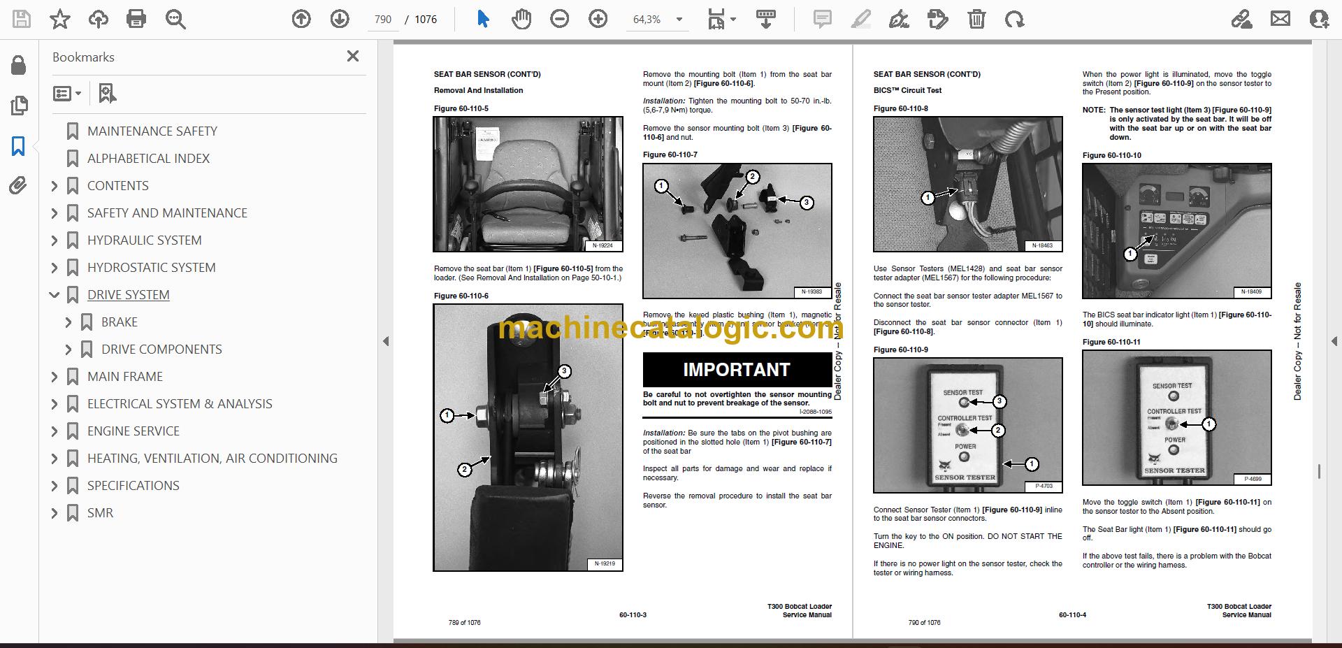
- SEAT BAR SENSOR
- Troubleshooting Chart
- Test
- Removal And Installation
- BICS™ Circuit Test
- TRACTION LOCK
- Troubleshooting Chart
- Description Of The Control System
- Inspecting The Control System
- Parking Brake Solenoid Removal And Installation
- ADVANCED CONTROL SYSTEM (ACS)
- Components Identification
- Troubleshooting Guide
- Controller, Connector And Wire Identification
- ACS Controller Removal And Installation
- Handle Sensor Connector
- Switch Handle Removal
- Switch Handle Installation
- Actuators Disassembly And Assembly
- Handle Lock Solenoid Removal And Installation
- Handle Lock Solenoid Disassembly And Assembly
- Handle Lock Solenoid Connector
- Foot Sensor Disassembly And Assembly
- Foot Sensor Connector
- Foot Lock Solenoid Removal And Installation
- Foot Lock Solenoid Connector
- ELECTRICAL/HYDRAULIC CONTROLS REFERENCE
- Controls Identification Chart
- ELECTRICAL/HYDRAULIC CONTROLS REFERENCE (selectable JOYstick control) (sjc)
- Controls Identification Chart
- SERVICE PC (LAPTOP COMPUTER)
- Connecting The Service PC To Remote Start Tool
- CALIBRATION
- Lift and Tilt Calibration Procedure (Selectable Joystick Control) (SJC)
- Hydrostatic Pump Calibration (Selectable Joystick Control) (SJC)
- Calibration Procedure (Advanced Control System) (ACS)
- FLYWHEEL RPM SENSOR
- ENGINE SERVICE
- TROUBLESHOOTING
- ENGINE SPEED CONTROL
- Removal And Installation
- Speed Control Cable
- ENGINE SPEED CONTROL (SELECTABLE JOYSTICK CONTROL) (SJC)
- Removal
- Disassembly
- Speed Control Cable
- MUFFLER
- AIR CLEANER
- Housing Removal And Installation
- RADIATOR
- Removal And Installation
- Mount Removal (Early Loaders)
- Mount Removal (Later Loaders)
- COOLING FAN
- Drive Tension Pulley Removal And Installation
- Gearbox/Blower Housing Removal And Installation
- Blower Removal And Installation
- Gearbox Parts Identification
- Gearbox Disassembly
- Gearbox Assembly
- Gearbox, Checking Backlash
- ENGINE
- Removal And Installation
- Mount Replacement
- Removal And Installation Tools
- FLYWHEEL AND HOUSING
- Flywheel Removal And Installation
- Ring Gear Removal And Installation
- Flywheel Housing Removal And Installation
- RECONDITIONING THE ENGINE
- Engine Tools Identification Chart
- Compression Pressure
- Cylinder Head Clearance
- Valve Cover, Injector Nozzle And Seal Removal And Installation
- Checking Nozzle Injection Pressure
- Nozzle Spraying Condition
- Valve Seat Tightness
- Rocker Arm And Push Rod Disassembly And Assembly
- Valve Clearance
- Cylinder Head And Tappet Disassembly And Assembly
- Selecting Cylinder Head Gasket Disassembly And Assembly
- Valve Disassembly And Assembly
- Engine Timing (TDC)
- Injection Pump Housing Removal
- Injection Pump Governor Housing Removal And Installation
- Injection Pump Governor Fork Lever Removal And Installation
- Injection Pump Governor Lever Removal And Installation
- Injection Pump Stop Lever Removal And Installation
- Injection Pump Fuel Camshaft And Governor Weight Removal And Installation
- Injection Pump Removal and Installation
- Injection Pump Housing Installation
- Injection Pump Timing
- Fan Drive Pulley Disassembly And Assembly
- Water Pump Disassembly And Assembly
- Oil Cooler And Water Pipe Disassembly And Assembly
- Gearcase Cover Disassembly And Assembly
- Idle Gear And Camshaft Disassembly And Assembly
- Oil Pan And Oil Strainer Disassembly And Assembly
- Connecting Rod Cap Disassembly And Assembly
- Piston Disassembly And Assembly
- Piston Ring And Connecting Rod Disassembly And Assembly
- Flywheel And Crankshaft Disassembly And Assembly
- Bearing Case Cover Disassembly And Assembly
- Flywheel Housing Disassembly And Assembly
- Crankcase No. 2 Disassembly And Assembly
- Crankcase No. 1 And No. 2 Disassembly And Assembly
- Crankshaft Disassembly And Assembly
- Cylinder Head Surface Flatness
- Cylinder Head Flaw
- Valve Recessing
- Valve Lapping
- Clearance Between Valve Stem And Valve Guide
- Replacing Valve Guide
- Correcting Valve And Valve Seat
- Free Length And Tilt Of Valve Spring
- Valve Spring Setting Load
- Oil Clearance Between Rocker Arm Shaft And Bearing
- Oil Clearance Between Tappet And Tappet Guide Bore
- Timing Gear Backlash
- Idler Gear Side Clearance
- Camshaft Side Clearance
- Camshaft Alignment
- Cam Height
- Oil Clearance Between Idler Gear Shaft And Idler Gearing Bushing
- Replacing Idler Gear Bushing
- Piston Pin Bore I.D.
- Oil Clearance Between Piston Pin And Small End Bushing
- Replacing Small End Bushing
- Clearance Between Piston Ring And Groove
- Piston Ring Gap
- Connecting Rod Alignment
- Crankshaft Side Clearance
- Crankshaft Alignment
- Oil Clearance Between Crankpin And Crankpin Bearing
- Oil Clearance Between Crankshaft Journal And Crankshaft Bearing
- Replacing Crankshaft Sleeve
- Cylinder Bore I.D.
- Correcting Cylinder (Oversize +0.5 mm)
- Engine Oil Pressure
- Rotor Lobe Clearance
- Clearance Between Outer Rotor And Pump Body
- Clearance Between Rotor And Cover
- Relief Valve
- Thermostat Valve Opening Temperature
- Radiator Water Leakage
- Radiator Cap Air Leakage
- Thermostat Assembly
- Intake Air Heater
- Air Cleaner, Intake Pipe, Inlet Pipe And Muffler
- Oil Pipe
- Turbocharger
- HEATING, VENTILATION, AIR CONDITIONING
- AIR CONDITIONING SYSTEM FLOW
- COMPONENTS
- SAFETY
- REGULAR MAINTENANCE
- Filter Elements Removal And Installation
- Compressor Drive Belt Inspection
- Cleaning The Condenser
- BASIC TROUBLESHOOTING
- Poor A/C Performance
- Cleaning The A/C Evaporator Coil & Heater Coil
- Compressor Drive Belt Inspection
- Checking The Electrical System
- Engine Coolant By-Passing The Heater Valve
- Heater Valve Not Opening Or Closing
- GENERAL AIR CONDITIONING SERVICE GUIDELINES
- Compressor Oil
- Compressor Oil Check
- Component Replacement And Refrigeration Leaks
- SYSTEM TROUBLESHOOTING CHART
- Gauge Pressure Related Troubleshooting
- Troubleshooting Tree
- TEMPERATURE/PRESSURE
- AIR CONDITIONING SERVICE
- SYSTEM CHARGING AND RECLAMATION
- Reclamation Procedure
- Charging Procedure With A Manifold Gauge Set
- Charging Procedure
- COMPRESSOR
- Removal And Installation
- Compressor Clutch Disassembly
- CONDENSER
- RECEIVER/DRIER
- PRESSURE RELIEF VALVE
- PRESSURE SWITCH
- EVAPORATOR/HEATER UNIT
- Removal And Installation
- Disassembly And Assembly
- THERMOSTAT
- EXPANSION VALVE
- EVAPORATOR
- HEATER COIL
- Removal And Installation With A/C
- Removal And Installation Without A/C
- BLOWER FAN
- Removal And Installation
- Disassembly And Assembly
- Wire Connector Removal and Installation
- HEATER VALVE
- Removal and Installation
- Disassembly And Assembly
- SPECIFICATIONS
- LOADER SPECIFICATIONS (T300)
- Machine Dimensions
- Performance
- Controls
- Engine
- Hydraulic System
- Electrical
- Drive System
- Capacities
- Tracks
- ENGINE SPECIFICATIONS
- General
- Fuel System
- Valve And Valve Timing
- Valve Spring
- Piston And Piston Ring
- Connecting Rod
- Cylinder Head
- Crankshaft
- Cylinder Bore
- Oil Pump
- Rocker Arm
- Tappet
- Camshaft
- Thermostat
- Timing Gear
- Intake Air Heater
- Turbocharger Compressor Shaft
- TORQUE SPECIFICATIONS FOR BOLTS
- Torque For General SAE Bolts
- Torque For General Metric Bolts
- Torque For Kubota Metric Engine Bolts
- Tightening Torques For General Use Screws, Bolts And Nuts
- HYDRAULIC CONNECTION SPECIFICATIONS
- O-ring Face Seal Connection
- Straight Thread O-ring Fitting
- Tubelines And Hoses
- Flare Fitting
- O-ring Flare Fitting
- Port Seal Fitting
- HYDRAULIC FLUID SPECIFICATIONS
- CONVERSIONS
- Decimal And Millimeter Equivalents
- SMR
- T300-1
- T300-2
- T300-3
- T300-4
- T300-5
Bobcat Software
Bobcat PDF Manuals


